

Page 1
Safety and operating manual
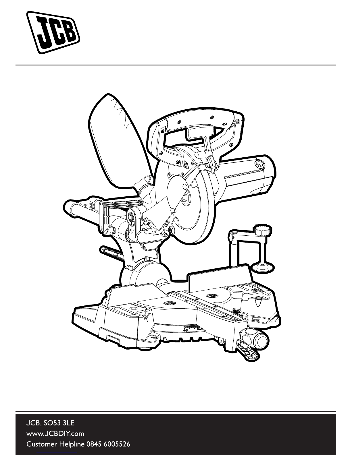
210mm Single Bevel Sliding Mitre Saw
JCB-SCMS210
Page 2

WARNING: Read all safety
warnings and instructions.
Failure to follow the warnings and
instructions may result in electric
shock, re and/ or serious injury.
Save all warnings and instructions
for future reference.
The term “power tool” in the warnings
refers to your mains-operated
(corded) power tool or battery-
operated (cordless) power tool.
1) Work area safety
a) Keep work area clean and well
lit. Cluttered or dark areas invite
accidents.
b) Do not operate power tools in
explosive atmospheres, such as in
the presence of ammable liquids,
gasses or dust. Power tools create
sparks which may ignite the dust or
fumes.
c) Keep children and bystanders
away while operating power tool.
Distractions can cause you to lose
control.
2) Electrical Safety
a) Power tool plugs must match the
outlet. Never modify the plug in any
way. Do not use any adapter plugs
with earthed (grounded) power tools.
Unmodied plugs and matching
outlets will reduce the risk of electric
shock.
b) Avoid body contact with earthed
or grounded surfaces, such
as pipes radiators, ranges and
refrigerators. There is an increased
risk of electric shock if your body is
earthed or grounded.
c) Do not expose power tools
to rain or wet conditions. Water
entering a power tool will increase the
risk of electric shock.
d) Do not abuse the cord. Never
use the cord for carrying, pulling or
unplugging the power tool. Keep
cord away from heat, oil, sharp
edges or moving parts. Damaged or
entangled cords increase the risk of
electric shock.
e) When operating a power tool
outdoors, use an extension cord
suitable for outdoor use. Use of a
cord suitable for outdoor use reduces
the risk of electric shock.
f) If operating a power tool in a
damp location is unavoidable, use
a residual current device (RCD)
protected supply. Use of an RCD
reduces the risk of electric shock.
3) Personal Safety
a) Stay alert, watch what you are
doing and use common sense
when operating a power tool. Do
not use a power tool while you
are tired or under the inuence of
drugs, alcohol or medication.
ORIGINAL INSTRUCTIONS
GENERAL POWER TOOL GENERAL SAFETY WARNINGS
Page 3

A moment of inattention while
operating power tools may result in
serious personal injury.
b) Use personal protective
equipment. Always wear eye
protection. Protective equipment
such as dust masks, non-skid safety
shoes, hard hat or hearing protection
used for appropriate conditions will
reduce personal injuries.
c) Prevent unintentional starting.
Ensure the switch is in the offposition before connecting to
power source and or battery pack,
picking up or carrying the tool.
Carrying power tools with your nger
on the switch or energising the power
tools that have the switch on invites
accidents.
d) Remove any adjusting key or
wrench before turning the power
tool on. A wrench or key left attached
to a rotating part of a power tool may
result in personal injury.
e) Do not overreach. Keep proper
footing and balance at all times.
This enables better control of the
power tool in unexpected situations.
f) Dress properly. Do not wear
loose clothing or jewellery. Keep
your hair, clothing and gloves away
from moving parts. Loose clothes,
jewellery or long hair can be caught in
moving parts.
g) If devices are provided for the
connection of dust extraction and
collection facilities, ensure that
these are connected and properly
used. Use of dust collection can
reduce dust-related hazards.
4) Power tool use and care
a) Do not force the power tool.
Use the correct power tool for your
application. The correct power tool
will do the job better and safer at a
rate for which it was designed.
b) Do not use the power tool if
the switch does not turn it on
or off. Any power tool that cannot
be controlled with the switch is
dangerous and must be repaired.
c) Disconnect the power tool from
the power source and/or battery
pack from the power tool before
making any adjustments, changing
accessories, or storing power
tools. Such preventative safety
measures reduce the risk of starting
the power tool accidentally.
d) Store idle power tools out of
the reach of children and do not
allow persons unfamiliar with the
power tool or these Instructions
to operate the power tool. Power
tools are dangerous in the hands of
untrained users.
e) Maintain power tools. Check for
misalignment or binding of moving
parts, breakage of moving parts
and any other condition that may
affect the power tools operation.
Page 4

If damaged, have the power tool
paired before use. Many accidents
are caused by poorly maintained
power tools.
f) Keep cutting tools sharp and
clean. Properly maintained cutting
tools with sharp cutting edges are
less likely to bind and are easier to
control.
g) Use the power tool, accessories
and tool bits etc. in accordance
with these instructions, taking into
account the working conditions
and the work to be performed.
Use of the power tool for operations
different from those intended could
result in a hazardous situation.
5) Service
a) Have your power tool serviced
by a qualied repair person using
only identical replacement parts.
This will ensure that the safety of the
power tool is maintained.
b) If the replacement of the supply
cord is necessary, this has to be
done by the manufacturer or its
agent in order to avoid a safety
hazard.
ADDITIONAL SAFETY
INSTRUCTIONS FOR YOUR
MITRE SAW
WARNING: Be sure to
read and understand all
instructions.
Failure to follow all instructions listed
below may result in electric shock,
re and/or serious personal injury.
1. Know your power tool. Read
operator’s manual carefully. Learn
the applications and limitations, as
well as the specic potential hazards
related to this tool.
2. Always wear safety glasses or
eye shields when using this mitre
saw. Everyday eyeglasses have
only impact-resistant lenses; they
are not safety glasses.
3. Always protect your lungs. Wear
a face mask or dust mask if the
operation is dusty.
4. Always protect your hearing.
Wear hearing protection during
extended periods of operation.
5. Inspect the machines power
cord regularly and if damaged have
it repaired or replaced. Always be
aware of the cords location.
6. Always check for damaged parts.
Before further use of the tool, a guard
or other part that is damaged should
be carefully checked to determine if
it will operate properly and perform
ORIGINAL INSTRUCTIONS
GENERAL POWER TOOL GENERAL SAFETY WARNINGS
Page 5

its intended function. Check for
misalignment or binding of moving
parts, breakage of parts, and any
other condition that may affect the
tool’s operation. A guard or other part
that is damaged should be properly
repaired or replaced at a qualied
service centre. Keep guards in place
and in working order.
7. Do not abuse the cord. Never
use the cord to carry the tool or pull
the plug from the outlet. Keep cord
away from heat, oil, sharp edges or
moving parts. Replace damaged
cords immediately. Damaged cords
increase the risk of electric shock.
8. Always make sure that your
extension cord is in good condition.
When using an extension cord be
sure to use one that is heavy enough
to carry the current that your tool will
draw. An undersized cord will cause
a drop in line voltage, resulting in loss
of power and overheating.
9. Do not use the tool while
tired or under the inuence of
drugs, alcohol or any medication.
Following this instruction will reduce
the risk of electric shock, re or
serious personal injury.
10. Save these instructions. Refer
to them frequently and use them to
instruct others who may use this tool.
If someone borrows this tool, make
sure they have these instructions
also.
11. Do not use saw blades with
High Speed Steel (HSS) or blades
that are damaged or deformed.
12. Replace the table insert when
worn.
13. Use only saw blades
recommended by the manufacturer
and which are the exact bore and
diameter required for this machine
and conform to EN 847-1
14. Connect your mitre saw to a dust
collecting device (I.D.Ø32mm) when
sawing material likely to cause dust.
15. Select saw blades in relation
to the material to be cut. Use
only genuine JCB recommended
accessories.
16. Check the maximum depth of cut.
17. When sawing long work
pieces, always use extra support
to provide better support, and use
clamps or other clamping devices.
To reduce the risk of injury, return the
slide carriage to the full rear position
after each crosscut operation.
18. Ensure that the operator is
adequately trained in the use
adjustment and operation and
operation of the machine.
19. Provide for adequate room
lighting at your workplace or for
adequate lighting of the immediate
work area.
20. When tted with a laser no
exchange with a different type
of laser is permissible. Repairs
Page 6

shall only be carried out by the laser
manufacturer or an authorised agent.
21. Refrain from removing any cutoffs or other parts of the workpiece
from the cutting area whilst the
machine is running and the saw
head is not in the rest position.
Never reach around the saw blade.
Turn off tool and wait for saw blade
to stop before moving workpiece or
changing settings.
22. Never stand on this tool. Serious
injuries could occur when this tool
tips over or when coming in contact
with the saw blade.
23. Reduce the risk of unintentional
starting. Make sure switch is in off
position before plugging in.
WARNING: The operation
of any mitre saw can result
in material being thrown towards
your face, and this could result
in severe eye damage. Before
beginning power tool operation,
always wear safety goggles, safety
glasses with side shields or a full
face shield.
WARNING: If any parts
are missing, do not operate
your mitre saw until the missing
parts are replaced. Failure to follow
this instruction could result in
serious personal injury.
WARNING: Some dust particles
created by power sawing contain
chemicals known to cause cancer,
birth defects or other reproductive
harm. Some examples of these
chemicals are:
• Lead from lead-based paints.
• Crystalline silica from bricks
and cement and other masonry
products.
• Arsenic and chromium from
chemically treated timber.
Your risk to these exposures varies
depending upon how often you do
this type of work. To reduce your
exposure to these chemicals:
• Work in a well ventilated area.
• Work with approved safety
equipment, such as those dust
masks that are specially designed
to lter microscopic particles.
ORIGINAL INSTRUCTIONS
GENERAL POWER TOOL GENERAL SAFETY WARNINGS
Page 7

ADVICE ON CARRYING
YOUR MITRE SAW
1. Although compact, this saw is
heavy. To reduce the risk of back
injury, get competent help whenever
you have to lift the saw.
2. To reduce the risk of back injury,
hold the tool close to your body
when lifting. Bending your knees so
you can lift with your legs, not your
back. Lift by using the handhold
areas at each side of the machines
base.
3. Never carry the mitre saw by the
power cord or the trigger grip of
the handle. Carrying the tool by the
power cord could cause damage to
the insulation or the wire connections
resulting in electric shock or re.
4. Before moving the saw tighten
the slide lock knob to guard
against sudden movement.
WARNING: Do not use the
blade guard as a
‘lifting point’.
The power cord must be removed
from the power supply before
attempting to move the machine.
• Lock down the head using the
head locking pin.
• Move the Cutting Head to its
outermost position and lock in
place by tightening the slide lock
screw.
• Loosen the mitre angle lock
knob. Pull up the mitre angle
positive locking lever and rotate
the table to either of its maximum
settings.
• Lock the table in position using
the locking knob.
• Use the two carry handle
cut-outs machined into either
side of the machine base, to
transport the machine.
Place the saw on a secure stationary
work surface and check the saw over
carefully. Check particularly the
operation of all the machines safety
features before attempting to operate
the machine.
Page 8
GENERAL SAFETY WARNINGS
FOR YOUR LASER
WARNING: Read all
safety warnings and all
instructions. Failure to follow the
warnings and instructions may
result in serious injury.
Save all warnings and instructions for
future reference.
These lasers do not normally present
an optical hazard although staring at
the beam may cause ash blindness.
Do not stare directly at the laser
beam. A hazard may exist if you
deliberately stare into the beam.
Please observe the following safety
rules:
1. The laser shall be used and
maintained in accordance with the
manufacturers instructions.
2. Never aim the beam at any person
or object other than the workpiece.
3. The laser beam must not be
deliberately aimed at another person
and should be prevented from being
inadvertently directed towards the
eyes of a person or animal.
4. Always ensure the laser beam is
only aimed at a workpiece without
reective surfaces e.g. natural
wood or matt or rough coated
surfaces are acceptable.
5. Do not replace the laser unit with
a different type. Repairs to the laser
unit must only be carried out by the
manufacturer or an authorised agent.
6. CAUTION: The use of any other
control devices or attempting any
adjustments other than those
specied in this Instruction Manual
may result in hazardous radiation
exposure.
ORIGINAL INSTRUCTIONS
GENERAL POWER TOOL GENERAL SAFETY WARNINGS
Page 9

ADDITIONAL SAFETY
WARNINGS FOR CLASS 2
LASER
The laser unit tted to this machine is
class 2 with a maximum radiation of
1mW and 650nm wavelength.
CLASS 2 LASER RADIATION
DO NOT STARE INTO THE BEAM
Page 10

SYMBOLS
To reduce the risk of injury, users must read instruction manual
Double Insualted
Warning
Wear ear protection
Wear eye protection
Wear dust mask
Waste electrical products should not be disposed of with
household waste. Please recycle where facilities exist.
Check with your local authorities or retailer for recycling advice.
LASER RADIATION
DO NOT STARE INTO BEAM
Page 11
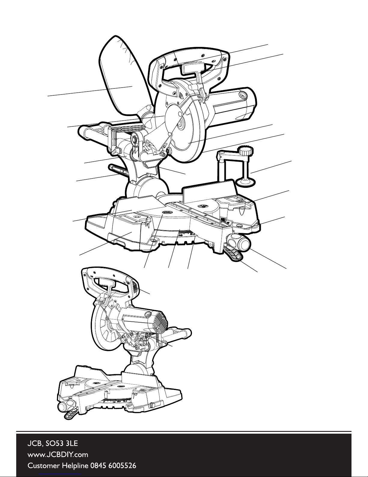
COMPONENT LIST
1
2
3
4
5
6
7
8
9
10
13
14
18
20
15
17
21
16
19
22
11
12
Page 12

1. MOTOR ON/OFF TRIGGER SWITCH
2. LOWER BLADE GUARD RELEASE LEVER
3. CUTTING HANDLE
4. DUST BAG
5. ROTARY TABLE
6. TABLE TOP
7. LOWER BLADE GUARD
8. UPPER BLADE GUARD
9. BLADE
10. CARRIAGE SLIDE LOCKING KNOB
11. BEVEL LOCKING LEVER
12. MITRE HANDLE LOCKING KNOB
13. MITRE ANGLE PROTRACTOR SCALE
14. POSITIVE STOP LOCKING LEVER
15. DEPLOYABLE WORKPIECE STAND
16. ADJUSTABLE REPEAT END STOP
17. FENCE
18. HOLD DOWN CLAMP
19. CUTTING HEAD LATCHING PIN
20. MOUNTING HOLE (X4)
21. LASER UNIT
22. LASER ON/OFF SWITCH
*Not all accessories illustrated are included as standard
Page 13
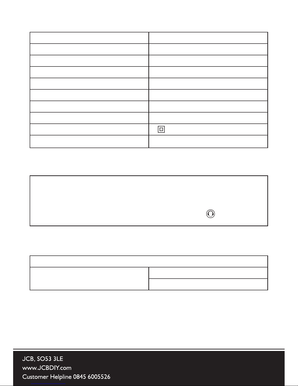
Voltage 230 – 240V ~50Hz
Power input 1400W
No load speed 4500 (min-1)
Blade diameter 210mm
Mitre angle adjustment 0 – 450 (right and left hand)
Bevel angle adjustment 0 – 450 (left hand only)
Wood (00 bevel angle) 240mm x 60mm
Wood (450 bevel angle) 240mm x 35mm
Protection class /2
Machine weight
14.05kg
NOISE INFORMATION
A weighted sound pressure LpA : 94dB(A)
A weighted sound power LwA : 107dB(A)
KpA & KwA = 3.0dB(A)
Wear ear protection when sound pressure is over: 80dB(A)
VIBRATION INFORMATION
Vibration total values (triax vector sum) determined according to EN 60745:
Typical weighted vibrationt Vibration emission value ah = 3.384m/s
2
Uncertainty K = 1.5m/s
2
TECHNICAL DATA
Page 14
WARNING: The vibration
emission value during actual
use of the power tool can differ from
the declared value depending on
the ways in which the tool is used.
The following examples (by no means
exhaustive) give some indication as to
why the vibration values may vary from
the declared gure:
1) How the tool is used and the
material being cut.
2) That the tool being used is in good
condition and well maintained.
3) That any accessory used is
designed for the tool, and that it is
sharp and in good condition.
4) The tightness of the operators grip
on the handles, and if any
anti-vibration accessories are used.
That the tool is being used as
intended by its design, and in
accordance with these instructions.
This tool may cause hand-arm
vibration syndrome if its use is not
adequately managed.
WARNING: To be accurate,
an estimation of exposure
level in the actual conditions of use
should also take account of all parts
of the operating cycle, such as the
times when the tool is switched off
and when it is running idle but not
actually doing the job. This may
signicantly reduce the exposure
level over the total working period.
Helping to minimise your vibration
exposure risk.
Aways use sharp chisels, drills and
blades.
Maintain this tool in accordance with
these instructions and keep it well
lubricated (where appropriate).
If the tool is to be used regularly then
invest in anti-vibration accessories.
Avoid using tools in temperatures of
100C or less.
Plan your work schedule to spread
any high vibration tool use across a
number of days.
Page 15

Hold Down Clamp 1
Hex Key (for Blade change) 1
210mm Wood Cutting Blade (tted) 1
Dust Bag 1
Safety & Instruction Manual 1
We recommend that you purchase your accessories from the same store that sold
you the tool. Use good quality accessories marked with a well known brand name.
Choose the type according to the work you intend to undertake. Refer to the accessory
packaging for further details. Store personnel can assist you and offer advice.
ACCESSORIES
Page 16

NOTE: Before using the tool,
read the safety and operating
manual carefully.
INTENDED USE
This product is a wood cutting
Sliding Mitre Saw and has been
designed to be used with JCB wood
cutting blades. Only use wood
blades designed for use in this
machine and/or those recommended
specically by JCB Power Tools.
When tted with a correct blade this
machine can be used to cut:
• Wood
• Wood derived products
(MDF, Chipboard, Plywood,
Blockboard, Hardboard etc)
DO NOT: Cut wood containing nails
or screws, as this will damge the
blade.
OPERATING INSTRUCTIONS
Page 17

PERMANENTLY MOUNTING
THE MITRE SAW
To reduce the risk of injury from
unexpected saw movement, place
the saw in the desired location either
on a workbench or other suitable
machine stand. The base of the saw
has four mounting holes through
which suitable bolts (not supplied)
can be placed to secure the mitre
saw. If the saw is to be used in one
location, permanently fasten it to
the workbench using appropriate
fastenings (not supplied). Use locking
washers and nuts on the underside of
the workbench. (See )
1) To avoid injury from ying debris,
position the saw so that other
people or bystanders cannot stand
too close (or behind) it.
2) Locate the saw on a rm, level
surface where there is plenty of
room for handling and properly
supporting the workpiece.
3) Support the saw so the machine
table is level and the saw does not
rock.
4) Bolt or clamp the saw securely
to its support stand or workbench.
1
1
Page 18

2
FOR PORTABLE USE:
1) Mount the saw on a 18mm thick
piece of plywood or MDF (800mm
x 500mm min size recommended)
using appropriate fastenings (not
supplied).
2) It may be necessary to
countersink the washers, nuts, etc.
to the underside of the plywood or
MDF mounting board to avoid an
uneven work surface.
3) Use G-clamps to attach the
mounting board to the work
surface. (See )
2
Page 19

3
OPERATION
1. THE HOLD DOWN CLAMP
(See )
Two sockets (one either side) are
incorporated into the rear of the
machines fence. These sockets are
for positioning the Hold Down Clamp.
1) Fit the clamp to the retaining
socket that best suits the cutting
application, ensuring that it is fully
pushed down.
2) Tighten the fence thumbscrew to
lock the pillar of the clamp into the
fence socket.
3) Place the workpiece to be cut
onto the saw table, against the
fence and in the desired position.
4) Adjust the clamp using the
thumbscrews and hand-wheel
so that it securely holds the
workpiece to the saw table.
Conduct a ‘dry run’ with the power
disconnected. Ensure that the Hold
Down Clamp does not interfere with
the path of the blade, or with the path
of any other part of the Cutting Head
as it is lowered.
3
Page 20

Laser ON/OFF Switch
4
4. THE LASER
This machine is equipped with a
Laser Cutting Guide. This allows the
operator to preview the path of the
blade through the workpiece. The
ON/OFF slide switch for the Laser
Guide is positioned in the Right Hand
edge of the Cutting Head ‘D’ handle.
(See ) Avoid direct eye contact
with the laser beam, and do not use
on material that could reect the laser
beam.
WARNING: Do not stare
directly at the laser beam.
A hazard may exist if you deliberately
stare into the beam. Please observe
all of the following
SAFETY RULES
1) The laser beam must not be
deliberately aimed at personnel
and must be prevented from being
directed towards the eyes of a
person.
2) Always ensure that the laser
beam is used only on workpieces
that have non-reective surfaces, i.e.
natural wood or matt surfaces etc.
3) Never exchange the laser
module assembly for a different
type or class of laser.
4) Repairs to the laser module must
only be conducted by JCB Power
Tools or their authorized agent.
4
Page 21

5. THE DUST BAG
A Dust Bag can be tted to the
extraction port at the rear of the
machine. The Dust Bag is for use
when cutting wooden materials.
1) Slide the Dust Bag over the dust
extraction port, ensuring that the
spring clip grips the port holding the
Dust Bag securely in place. (See )
NOTE: For operational efciency
empty the Dust Bag when it becomes
2/3 full. Dispose of the contents of
the Dust Bag in an environmentally
responsible way. It may be necessary
to wear a dust mask when emptying
the Dust Bag.
NOTE: A workshop vacuum
extraction machine can be attached
to the dust extraction port if required.
Follow the manufacturers instructions
if such a machine is tted.
6. DEPLOYABLE REMOTE
WORKPIECE STAND
Incorporated into the Left Hand side
of the machine base is a deployable
workpiece stand. Use this stand to
help support long pieces of material.
1) To remove the deployable stand,
press the release button on the top,
and slide the stand from the machine
base. Position where convenient to
adequately support long workpieces.
(See )
5
6
6
5
Page 22

7
2) To replace, simply slide the
deployable stand back into the
machine base until the release button
provides positive location.
7. ADJUSTABLE STOP PLATE
A stop plate designed for use during
repetitive cutting is incorporated
into the Extension Arm on the Right
Hand side of the machine base. The
stop plate can be deployed in two
positions, inboard and outboard.
To deploy the stop inboard:
1) Slide the spring-loaded release
lock forwards. (See )
2) Pull the stop from its stored
position upwards and to the left.
The stop will deploy to the inboard
position.
3) Slide the release lock backwards to
lock the stop into position. (See )
4) To stow away, reverse the above
steps.
To deploy the stop outboard:
1) Slide the spring-loaded release
lock forwards.,
2) Pull the stop from its stored
position upwards and to the right.
The stop will deploy to the outboard
position.
3) Slide the release lock backwards to
lock the stop into position. (See )
4) To stow away, reverse the above
steps.
7
8
9
8
9
Page 23

8. PRECISE POSITIONING OF
THE STOP PLATE
Deploy the stop plate to the inboard
or outboard position as outlined
above.
1) Push the release button on the
front of the machine base below the
stop plate.
2) Slide the Extension Arm from the
machine base, and release the button
when at the approximate required
distance. (See )
NOTE: The extension arm has a
micro adjustment facility for nal
positioning.
1) Turn the adjustment knob
clockwise or counter clockwise as
required for nal exact positioning of
the stop plate.
9. THE EXTENSION ARM
(See )
With the stop plate in its stored
position the extension arm can be
used to support long workpieces.
To deploy the Extension Arm:
1) Push the release button on the
front of the machine base below the
stop plate.
2) Slide the Extension Arm from the
machine base, and release the button
when at the required distance.
10
11
Page 24

10. THE DEPTH STOP (See )
The depth stop allows slots to be
cut in the workpiece. The downward
travel of the Cutting Head can be
set so that the saw blade does
not completely cut through the
workpiece.
NOTE: It is advisable that the depth
of cut is checked using a scrap piece
of timber to ensure that the slot cut is
correct.
NOTE: By making a cut in the
workpiece, and then repeating the
cut but with the workpiece slightly
repositioned to the left or right, it is
possible to perform trenching cuts.
To use the depth stop:
1) Deploy the depth stop plate.
(See )
2) Loosen the locking nut.
3) Adjust the thumb knob to limit the
saw blades travel to the required
depth.
4) Once set to the desired depth,
tighten the thumb nut against the
retaining bracket to lock the depth
stop and ensure that there is no
movement.
5) When cutting is complete, return
the depth stop plate to its original
position. This will allow the Cutting
Head to be locked in the down
position by the head latching pin.
12
13
12
13
Page 25

WORKING INSTRUCTIONS
CAUTION: The Mitre Saw should be
inspected (particularly for the correct
functioning of the safety guards)
before each use. Do not connect the
saw to the power supply until a safety
inspection has been carried out.
Ensure that the operator is
adequately trained in the use,
adjustment and maintenance of the
machine, before connecting to the
power supply and operating the saw.
WARNING: To reduce the
risk of injury, always unplug
the saw before changing or adjusting
any of the machines parts. Compare
the direction of the rotation arrow on
the guard to the direction arrow on
the blade. The blade teeth should
always point downward at the front of
the saw. Check the tightness of the
arbor screw.
Page 26

No-Hands Zone
14
PREPARING TO MAKE A CUT
BODY and HAND POSITIONING
(See )
NOTE: Correct operator stance and
positioning is very important when
operating any Mitre Saw.
1) Never place your hands within
the ‘no hands zone’ (at least 150mm
away from the blade). Keep hands
away from the path of the blade.
2) Secure the workpiece rmly to the
table and against the fence to prevent
any movement.
3) Use a Hold Down Clamp if possible
but check that it is so positioned that
it does not interfere with the path of
the blade or other moving machine
parts.
4) Avoid awkward operations and
hand positions where a sudden slip
could cause your ngers or a hand to
move into the blade.
5) Before attempting a cut, make a
‘dry run’ with the power off so that
you can see the path of the blade.
6) Keep your hands in position until
the ON/OFF trigger switch has
been released and the blade has
completely stopped.
14
Page 27

DO NOT OVER-REACH
Keep good footing and balance.
Stand to one side so that your face
and body are out of line of a possible
kickback.
WARNING: Freehand cutting
is a major cause of accidents
and should not be attempted.
1) Ensure that the workpiece is
always rmly resting against the
fence, and where practical is clamped
with the Hold Down Clamp to the
table.
2) The saw table should be clean and
free from any sawdust etc. before the
workpiece is clamped into position.
3) Ensure that the ‘cut-off’ material
is free to move sideways away from
the blade when the cut is completed.
Ensure that the ‘cut-off’ piece cannot
become ‘jammed’ in any other part of
the machine.
4) Do not use this saw to cut small
pieces. If the workpiece being cut
would cause your hand or ngers to
be within 150mm of the sawblade,
the workpiece is too small.
Page 28

RELEASING THE CUTTING HEAD
The Cutting Head will automatically
rise to the upper position once it
is released from the locked down
position.
It will automatically lock in the upper
position.
To Release the Cutting Head from the
Locked Down position:
1) Gently press down on the Cutting
Handle.
2) Pull out the Cutting Head latching
pin (See ) and allow the Cutting
Head to rise to its upper position.
If Release is Difcult:
1) Gently rock the Cutting Head up
and down.
2) At the same time twist the Head
Latching Pin clockwise and pull
outwards.
NOTE: We recommend that when
the machine is not in use the Cutting
Head is locked in its down position
with the latching pin fully engaged in
its socket.
15
Page 29

17
18
THE MOTOR ON/OFF SWITCH
(See )
The ON/OFF Motor Trigger
Switch is a non-latching type. It is
ergonomically positioned on the
inside of the Cutting Head ‘D’ handle.
1) Press the switch to start the motor.
2) Release the switch to turn off the
motor.
BASIC CHOP CUTTING
This type of cut is used mainly for
cutting small or narrow section
material. The Cutting Head is gently
pushed down to cut through the
workpiece.
The Sliding Carriage should be
locked in its rearmost position.
(See )
1) Slide the Cutting Head to the rear
as far as it will go.
2) Tighten the slide lock screw. (See
3) Place the the workpiece on the
table and against the fence and
secure with clamp(s) as appropriate.
4) Grasp the saw handle.
5) Turn the motor on and allow the
saw blade to reach full speed.
6) Operate the lower guard locking/
release lever to release the Cutting
Head. (See )
7) Lower the Cutting Handle
downwards and cut through the
workpiece.
16
17
18
19
Page 30

8) Allow the speed of the blade to
do the work, there is no need to
apply undue pressure to the Cutting
Handle.
9) When the cut has been completed,
release the ON/OFF trigger switch.
10) Allow the blade to come to a
complete stop.
11) Allow the Cutting Head to rise
to its upper position, with the lower
blade guard completely covering the
blade teeth, and the Cutting Head
locked in the upper position, before
releasing the Cutting Handle.
12) Remove the workpiece
BASIC SLIDE CUTTING
This saw is equipped with a Sliding
Carriage system.
Loosening the slide lock screw
will release the slide and allow the
Cutting Head to move forwards and
backwards. (See )
The saw blade is lowered into the
workpiece and then pushed to the
rear of the machine to complete a
cut. This type of cut can be used for
cutting wide pieces.
1) Position the workpiece on the table
and against the fence and secure
with clamp(s) as appropriate.
2) Loosen the slide lock screw.
3) Grasp the Cutting Handle and pull
the Cutting Head forward until the
arbor (centre of saw blade) is over the
front edge of the workpiece. (See )
4) Operate the ON/OFF motor trigger
20
21
Page 31

switch and allow the saw blade to
reach full speed.
5) Press the lower blade guard
locking lever for Cutting Head
release.
6) Push the Cutting Handle all the
way down and cut through the
leading edge of the workpiece.
7) Gently push the Cutting Handle
rearwards towards the fence
completing the cut.
8) Always push the Cutting Head to
the full rear position during each cut.
9) When the cut has been completed,
release the trigger switch and allow
the blade to come to a complete
stop.
10) Allow the Cutting Head to rise
to its upper position, with the lower
blade guard completely covering the
blade teeth, and the Cutting Head
locked in the upper position, before
releasing the Cutting Handle.
WARNING: Never pull the Cutting
Head and spinning blade towards
you when making a sliding cut. The
blade may try to climb up on top of
the workpiece, causing the Cutting
Head to ‘Kickback’ forcefully.
The Cutting Head should always be
positioned as outlined above before
attempting to make a sliding cut.
When the Cutting Head is in the
correct position above the workpiece
it can be lowered and pushed
rearwards towards the fence to
complete the cut.
Page 32

23
BASIC MITRE CUTTING (See )
The rotary table of this machine can
be turned through 450 to the left or
right from the normal cross-cut (00)
position.
Positive stops are provided at 450,
31.60, 22.50, 150, 100, 50 and 00 to
both the right hand and left hand
sides.
Mitre Cutting is possible with or
without the Sliding Carriage system
being deployed.
1) Loosen the Mitre Lock Handle
(See ) by turning it anti-clockwise.
2) Pull up the Positive Stop Locking
Lever.
3)Turn the rotary table to the desired
angle. A mitre angle protractor scale
is incorporated into the machines
base to aid setting.
4) Tighten the Mitre Lock Handle
when the angle is achieved.
NOTE: It is good practice to tighten
the Mitre Lock Handle even if a
Positive Stop has been selected and
the Positive Stop Locking Lever is
engaged.
BASIC BEVEL CUTTING
(See )
The Cutting Head can be set at any
angle up to a 450 to the Left Hand
side only.
The Bevel Angle Lock Handle is
found at the rear of the machine.
Positive stops are located at 00 (blade
vertical), 33.90 and 450.
22
23
24
Page 33

NOTE: The Bevel Angle Locking
Screw has a spring loaded lever.
(See ) This enables the lever to be
repositioned on the locking screw.
Repositioning may be necessary
to allow the screw to be tightened
sufciently to lock the Cutting Head
in the required position.
1) Loosen the Bevel Lock Handle
2) Tilt the Cutting Head to the desired
angle. A protractor guide is provided
behind the Bevel Lock Handle to aid
setting.
3) Ensure the handle is tightened
securely when the required angle has
been achieved.
COMPOUND CUTTING (See )
A compound cut is a combination of
a mitre and bevel cut.
1) Select the required mitre angle as
previously described in BASIC Mitre
CUTTING.
2) Select the required bevel angle as
previously described In BASIC BEVEL
CUTTING.
3) Ensure the tightness of all
adjustment/locking screws before
making a cut.
CUTTING BOWED MATERIAL
Before cutting any workpiece, check
to see if it is bowed. If it is bowed the
workpiece must be positioned and
cut as shown. (See )
Do not position the workpiece
incorrectly or cut the workpiece
without the support of the fence.
25
26
27
Page 34

CLEARING JAMMED MATERIAL
1) Turn mitre saw “OFF” by releasing
the trigger switch.
2) Allow the blade to come to a
complete halt.
3) Unplug the mitre saw from the
mains supply.
4) Carefully remove any jammed
material from the machine.
5) Check the condition and operation
of the safety guard.
6) Check for any other damage to any
part of the machine e.g. the blade.
7) Have any damaged parts replaced
by a competent technician and a
safety inspection carried out before
using the machine again.
CUTTING CROWN MOULDING
Your JCB Sliding Mitre Saw is
suited to the difcult task of cutting
crown moulding. To t properly,
crown moulding must be compound
mitred with extreme accuracy. The
two surfaces on a piece of crown
moulding that t at against the
ceiling and wall are at angles that,
when added together, equal exactly
90°.
33.90 CROWN MOULDING BEVEL
STOP
A positive stop set at 33.90 to the Left
Hand is available when the Crown
Moulding Pin is deployed. (See )
28
Page 35

1) Twist the moulding pin ¼ of a turn
in either direction to deploy the pin.
2) Pull out and twist ¼ turn in either
direction to lock the pin in the
released position.
Most crown moulding has a top rear
angle (the section that ts at against
the ceiling) of 52° and a bottom rear
angle (the section that ts at against
the wall) of 38°.
In order to accurately cut crown
moulding for a 90° inside or outside
corner, lay the moulding with its
broad back surface at on the saw
table. When setting the bevel and
mitre angles for compound mitres,
remember that the settings are
interdependent – changing one
changes the other, as well.
Bevel/Mitre Settings for Crown
Moulding
Settings for standard crown moulding
lying at on a compound mitre saw
table.
IL
IR
OL
OR
Inside Corner
Outside Corner
Compound Cut Crown Mouldings
NOTE: The chart below references
a compound cut for crown moulding
ONLY WHEN THE ANGLES
BETWEEN THE WALLS EQUALS 90
0
KEY BEVEL MITRE TYPE OF CUT
SETTING
Inside Corner-Left side
IL 33.90 31.60 Right
1) Position top of moulding
against fence
2) Mitre table set at Right 31.6
0
3) Left side is nished place
1) Position bottom of moulding
against fence
2) Mitre table set at Right 31.6
0
1) Position bottom of moulding
against fence
2) Mitre table set at Left 31.6
0
3) Right side is nished place
1) Position top of moulding
against fence
2) Mitre table set at Right 31.6
0
3) Right side is nished place
IR 33.90 31.60 Left
OL 33.90 31.60 Left
OR 33.90 31.60 Right
Outside Corner-Left side
SETTING
Inside Corner-Right side
Outside Corner-Right side
Page 36

CHECKING AND SETTING OF
PRECISION ANGLES
WARNING: Only attempt
these procedures with the
machine disconnected from the
power supply.
NOTE: When checking angular
alignments the Cutting Head should
be lowered and locked in the down
position with the latching pin fully
located in its socket.
00 Bevel Stop Adjustment
1. Ensure that the Cutting Head is
upright against its stop and the Bevel
Pointer is indicating ‘00’ on the scale.
(See )
2. Place a combination square (not
supplied) on the mitre table with one
edge against the table and the other
edge against the blade. (See )
3. If the blade is not 900 square with
the mitre table adjustment is required.
4. Loosen the Bevel Lock Handle and
tilt the Cutting Head to the left.
5. Loosen the locknut on the Bevel
Angle Adjustment Screw. (See )
6. Use an Hex Key to adjust
the screw in or out to adjust the
inclination of the blade.
7. Return the Cutting Head to its
upright position and recheck angular
alignment against the combination
square.
30
31
29
Page 37

8. Repeat steps 1 to 7 until correct
angular alignment is achieved.
9. Tighten the Bevel Angle
Adjustment Screw locknut securely.
00 Bevel Pointer Adjustment
NOTE: The operator must be
satised that the blade is exactly
perpendicular to the table when in the
upright position and against its stop.
1. If the pointer is not in exact
alignment with the 00 mark on the
protractor scale adjustment is
necessary.
2. Loosen the Bevel Pointer screw
using a #2 Phillips screwdriver.
3. Adjust the Bevel Pointer so that
it is in alignment exactly with the 00
mark.
4. Retighten the screw.
450 Bevel Stop Adjustment
NOTE: Ensure that the 33.90 Crown
Moulding Pin is in its disengaged
(outer) position. (See )
1. Loosen the Bevel Lock Handle and
tilt the Cutting Head completely to the
left until it rests against the 450 stop.
2. Use set square to see if the blade
is at 450 to the table.
3. If the saw blade is not in exact
alignment adjustment is necessary.
4. Return the Cutting Head to its
upright position.
32
Page 38

5. Loosen the locknut on the 450
Bevel Adjustment Screw.
6. Use an Hex Key to adjust the
Adjustment Screw in or out as
required. (See )
7. Tilt the Cutting Head to the 450
setting and recheck for alignment
with the combination square.
8. Repeat steps 1 to 7 until the
correct angular alignment is achieved.
9. Tighten the Adjustment Screw
locknut securely once alignment is
achieved.
33.90 Bevel Stop Adjustment
If necessary the 33.90 settings can
be checked and adjusted. A vernier
angle gauge will be required and this
must be accurately set to 33.90.
To deploy the Crown Moulding Pin:
1. Pull the pin out slightly and turn ¼
in either direction (See )
2. Release the pin.
Tilt the Cutting Head to the 33.90
setting.
3. Check the angle of the blade
against the machine table using the
vernier angle gauge.
4. If adjustment is required loosen the
locknut to the 33.90 socket headed
stop screw. Adjust the screw in or
out until the correct bevel angle is
achieved. (See )
5. Retighten the locknut.
33
34
35
Page 39

Fence Adjustment
The fence must be aligned at 900
(square) to a correctly installed blade
The rotary table must be set at ‘00’
mitre angle.
The Fence is fastened to the table
with four (4) socket head hex screws
that are positioned two (2) at either
side in elongated slots.(See )
1. Place a set square on the table
with one short edge against the
Fence and the other short edge
against the Blade.
2. If adjustment is necessary, loosen
the four (4) Fence adjustment screws
using an Allen Key.
3. Re-position the Fence in its
elongated slots until alignment is
achieved.
4. Securely tighten the socket head
screws.
Mitre Angle Pointer Adjustment
NOTE: There are dual mitre angle
scales cast into the front of the
machines base. A small pointer
indicates the angle selected.
Set the rotary table to 00 Mitre
ensuring that the 00 Positive Stop
is engaged. Check that the Mitre
pointer is in exact alignment with the
00 index mark.
36
Page 40

If necessary the pointer can be
repositioned by loosening its
fastening screw using a #2 Phillips
screwdriver, adjusting as necessary
and then tightening the xing screw
securely.
CUTTING HEAD TRAVEL
Cutting Head Downward Travel
Adjustment (See )
To prevent the blade from contacting
any part of the machine metal base
the downward travel of the Cutting
Head can be adjusted.
Lower the Cutting Head and check
for any blade contact with the
machines base.
If the downward travel of the Cutting
Head needs to be adjusted:
1. Loosen the locknut on the
downward travel stop screw.
2. Turn the adjusting screw out
(counter-clockwise) to decrease the
downwards travel of the Cutting
Head.
3. Turn the adjusting screw
in (clockwise) to increase the
downwards travel of the Cutting
Head.
4. Tighten the adjustment screw
locknut when satisfactory downward
travel of the Cutting Head is
achieved.
37
Page 41

INSTALLING OR
REMOVING A BLADE
WARNING: Only use JCB
recommended blades which are
designed for this machine. Ensure
that the maximum speed of the blade
is compatible with the machine.
Only carry out this operation with
the machine disconnected from the
power source.
NOTE: Wear protective gloves when
handling the blade during installation
and removal.
1. Ensure the cutting head is up.
2. Push the button at the front of
the auxiliary guard, and rotate the
auxiliary guard to expose the arbor
bolt. (See )
3.Operate the lower blade guard
release lever & rotate the lower guard
up and into the upper blade guard to
gain access to the machines arbor.
(See )
4. Press the arbor lock button to lock
the arbor. (See )
5. Using the supplied Hex key release
the arbor screw to remove the blade.
NOTE: The arbor screw is reverse
threaded. Turn to the right to loosen
and to the left to tighten.
38
39
40
Page 42

6. Install the new blade. Make sure
the rotation arrow on the blade
matches the rotation arrow on the
upper blade guard
NOTE: The blade teeth should always
point downwards at the front of the
saw.
7. Install the washer, outer blade
ange and arbor screw. (See )
8. Lock the arbor and tighten the
arbor screw using moderate force,
but do not overtighten.
9. Ensure the Hex Key is removed
and the arbor lock has released by
rotating the blade by hand.
10. Return the Auxiliary Guard to its
operational position.
11. Ensure that all blade guards
are correctly positioned and fully
functional.
12 Return the Hex Key to its
‘on-board’ storage position.
NOTE: Spacers and spindle rings
should not be used with this machine
and/or blade.
WARNING: Ensure that the blade
collars are clean and correctly
positioned on the arbor.
Lower the blade into the table and
check for any contact with the table
or table insert.
41
Page 43

MAINTENANCE
Note: Any maintenance must be carried out with the machine switched off and
disconnected from the mains/battery power supply.
Check that all safety features and guards operating correctly on a regular basis.
Only use this machine if all guards/safety features are fully operational.
All motor bearings in this machine are lubricated for life. No further lubrication is
required.
Use a clean, slightly damp cloth to clean the plastic parts of the machine.
Do not use solvents or similar products which could damage the plastic parts.
WARNING: Do not attempt to clean by inserting pointed objects through openings
in the machines casings etc. The machines air vents should be cleaned using
compressed dry air.
Excessive sparking may indicate the presence of dirt in the motor or worn out
carbon brushes. If this is suspected have the machine serviced and the brushes
replaced by a qualied technician
Table Inserts
A two piece table insert is tted to this machine. If either side is damaged or worn,
both parts must be replaced. Replacement inserts (sold in handed pairs) are
available from Evolution Power Tools.
To replace the table inserts:
• Remove the 3 or 4 cross-head screws that secure one of the inserts to
the rotary table.
• Lift the insert from the table.
• Remove any debris that may have accumulated under the insert.
• Fit the replacement insert, and replace the three xing screws.
• Repeat the process for the other side.
• Check that all 6 or 8 xing screws are tightened securely, and that both
inserts are lying ush and level within the table.
Page 44

ENVIRONMENTAL PROTECTION
Waste electrical products should not be disposed of with household waste.
Please recycle where facilities exist. Check with your local authorities or
retailer for recycling advice.
PLUG REPLACEMENT (UK & IRELAND ONLY)
If you need to replace the tted plug then follow the instructions below.
IMPORTANT:
The wires in the mains lead tted to this product are coloured in accordance with the
following code:
Brown: Live (L)
Blue: Neutral (N)
THIS PRODUCT IS DOUBLE INSULATED AND THEREFORE DOES NOT REQUIRE A
CONNECTION TO EARTH.
• THE 3 PIN PLUG MUST COMPLY TO BS1363/A.
• THE FUSE MUST COMPLY TO BS1362.
If for any reason the 13 amp moulded plug tted to this product requires replacing,
the replacement must be wired in accordance with the following instructions:
• Connect the Blue wire to the terminal marked Neutral (N).
• Connect the Brown wire to the terminal marked Live (L).
Ensure that the outer insulation is gripped by the cord grip and that the wires are not
trapped when replacing the plug cover.
A 13 amp (BS1362) fuse must be tted in the plug.
Do not connect any wire to the earth pin MARKED E on the 3 pin plug.
NOTE: If a moulded plug is tted and has to be removed, take great care in disposing
of the plug and severed cable. It must be destroyed to prevent it ever again engaging
into a socket.
ENVIRONMENTAL PROTECTION
Waste electrical products should not be
disposed of with household waste.
Please recycle where facilities exist.
Check with your Local Authority or
retailer for recycling advice.
PLUG REPLACEMENT
The fuse in the main plug of your power tool
should always be replaced with one of
identical rating.
Check the voltage given on your power tool
matches the supply voltage.
The power tool is supplied with a fi tted plug,
however if you should need to fi t a new plug
follows the instruction below.
IMPORTANT
The wire in the mains lead are coloured in
accordance with the following code:
Blue ---Neutral
Brown ---Live
The wire that is coloured blue must be
connected to the terminal that is marked with
the letter N. The wire that is coloured brown
must be connected to the terminal that is
marked with the letter L. A 13AMP (BS1363
or BS1363/A) plug must be used and a 5 AMP
fuse must be fi tted.
A 13AMP (BS1363 or BS1363/A) plug must be
used and a 5 AMP fuse must be fi tted.
5 AMP
FUSE
BROWN
L (LIVE)
CABLE GRIP
OUTER
SLEEVE
BLUE
N (NEUTRAL)
13
Page 45

WARRANTY STATEMENT
Cutting edge construction technology in your hands
In 1945 JCB began producing construction equipment. Today, we build the world’s
number one diggers, each one the product of our unswerving focus on innovation,
quality and engineering. JCB power tools are built to give you the same world beating
standards of performance. The same innovation, to always get the job done better, the
same quality, to never let you down, the same engineering heritage and expertise that
you can trust 100%.
JCB power tools are guaranteed against manufacturing defects for a period of 5
years from the date of purchase. If your JCB power tool becomes defective within this
warrantee period, we guarantee to:
• Replace or repair all defective parts free of charge, or
• Repair products free of charge, or
• Replace the unit with a new or re-conditioned unit, free of charge.
Conditions
Your 1 year guarantee does not cover defects caused by or resulting from:
• overload, misuse, or neglect
• normal wear and tear, including accessory wear
• trade or hire use
• repairs attempted by anyone other than an authorized agent
• damage caused by foreign objects, substances or accidents.
Your 1 year guarantee does not cover:
• battery packs as they are guaranteed for a 12 month period
• accessories supplied with the power tool.
Warranty claims
For guarantee claims, please contact JCB Customer Services. You will be required to
submit proof of purchase.
JCB CUSTOMER HELPLINE 0845 600 5526
Terms
This guarantee does not affect your statutory rights. JCB SO53 3LE (Registered in
England under No. 973387).
Page 46

EC DECLARATION OF CONFORMITY
We,
Evolution Power Tools S20 3FR, UK
Declare that the product
Description
JCB Single Bevel Sliding Compound Mitre Saw
Type
(JCB-SCMS 210)
Function
Cutting wood materials with a rotating toothed blade
Complies with the following Directives,
EC Machinery Directive
2006/42/EC
EC Low Voltage Directive
2006/95/EC
EC Electromagnetic Compatibility Directive
2004/108EC
Standards conform to
EN 55014-1
EN 55014-2
EN 6100-3-2
EN 6100-3-3
EN 61029-2-9
EN 61029-1
The person authorized to compile the technical le,
Name: Steve Bulloss
Address: EVOLUTION Power Tools Ltd
Venture One, Longacre Close
Holbrook Industrial Estate, Shefeld
S20 3FR, UK
1/6/2012
Quality Control Manager
EVOLUTION
Page 47

Page 48

 Loading...