

Page 1
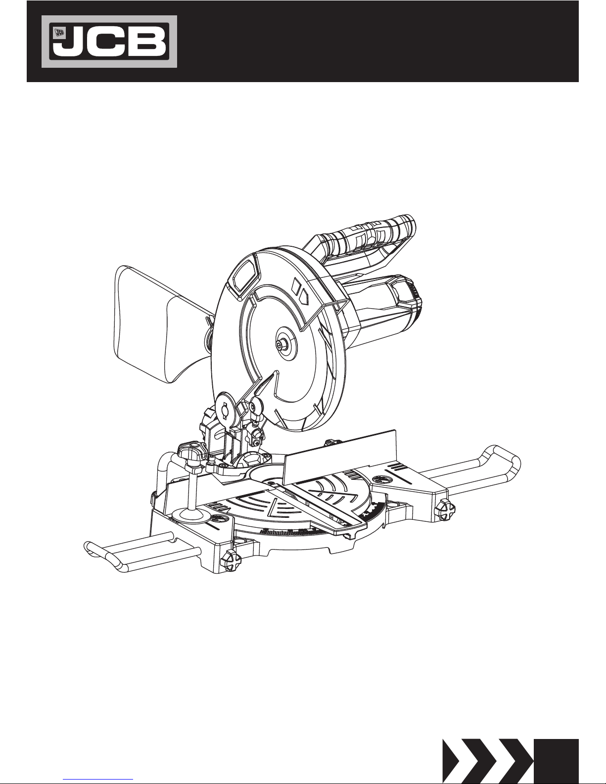
POWER TOOL
INSTRUCTION & USER MANUAL
EN
JCB-MS-210C
Original Instructions
IM-MS-210C-EN
Page 2

2
JCB-MS-210C
Instruction & User Manual
Page 3
3
JCB-MS-210C
Instruction & User Manual
GENERAL WARNINGS & DISPOSAL
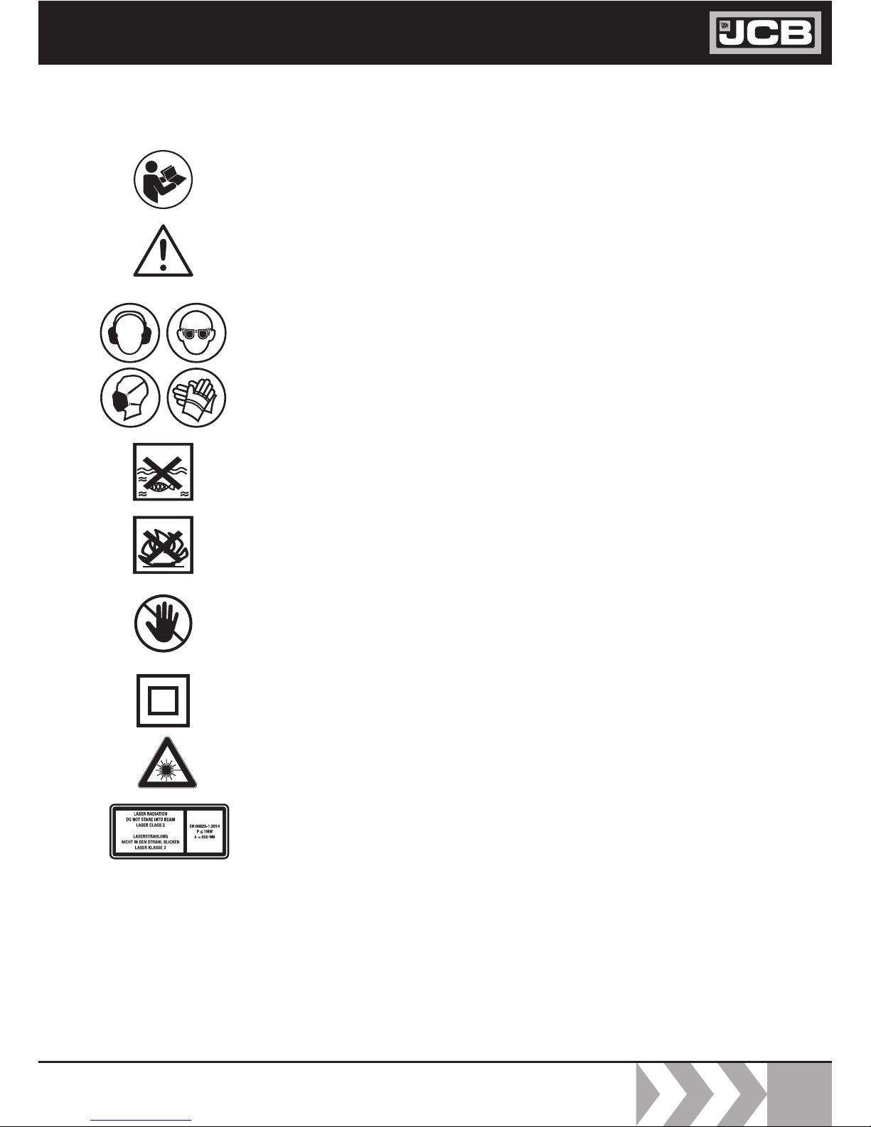
To reduce the risk of injury, user must read the instruction manual
This symbol is used throughout this manual to warn the user
about potential risks. Please read & understand these sections
before using the device.
Personal Protective Equipment (P.P.E.) must be worn during the
operation of the device.
The device must not be exposed to rain or immersed in water.
Do not allow any part of the device to come into contact with
flame, or to catch fire.
Warning! Risk of injury! Do not touch the moving saw blade!
Protection rating II (double insulated)
This mitre saw is equipped with a class 2 laser.
Do not look into the laser beam
The month and year of manufacture can be found within the product serial number e.g.
MMYYPPPAXXXXX. Where production month (MM) and production year (YY) are included.
Page 4

4
JCB-MS-210C
Instruction & User Manual
Contents
GENERAL SAFETY INSTRUCTIONS 5
Save all warnings and instructions for future reference 5
SAFETY INSTRUCTIONS FOR MITRE SAWS
7
Safty instructions for the handling of saw blades 9
COMPONENT LIST 12
TECHNICAL DATA 13
VIBRATION AND NOISE INFORMATION 14
OPERATING INSTRUCTIONS 15
SETTINGS AND WORKING INSTRUCTIONS 19
Intended Use 15
Commissioning 15
Assembly 17
Area of application 18
Settings 19
Working instructions 19
Cross cut 90° and turntable 0° 20
Cross cut 90° and turntable 0° - 45° 21
Mitre cut 0°- 45° 21
Mitre cut 0°- 45° and turntable 0°- 45° 22
Saw blade replacement 23
Adjusting the laser 24
Maintenance 24
Electrical connection 25
AC motor 25
Storage 25
DISPOSAL AND RECYCLING 26
WARRANTY STATEMENT 28
Conditions 28
Terms 29
EC DECLARATION OF CONFORMITY 31
Page 5

5
JCB-MS-210C
Instruction & User Manual
GENERAL SAFETY
INSTRUCTIONS
Read all safety warnings instructions,
illustrations and specifications
provided with this power tool.
Failure to follow the warnings and
instructions may result in electric shock, fire
and/or serious injury. The term "power tool"
in the warnings refers to your mainsoperated (corded) power tool or batteryoperated (cordless) power tool.
WARNING!
Save all warnings and instructions
for future reference.
1 Work area safety
2 Electrical safety
a
Keep work area clean and well lit
a Power tool plugs must match the outlet.
Never modify the plug in any way. Do not
use any adapter plugs with earthed
(grounded) power tools
– Cluttered and dark areas invite
accidents.
– Power tools create sparks which may
ignite the dust or fumes.
b
Do not operate power tools in
explosive atmospheres, such as in the
presence of flammable liquids, gases
or dust.
– Distractions can cause you to lose
control.
– Unmodified plugs and matching outlets
will reduce risk of electric shock.
c Keep children and bystanders away
while operating a power tool.
b Avoid body contact with earthed or
grounded surfaces such as pipes,
radiators,ranges and refrigerators.
–
There is an increased risk of electric shock
if your body is earthed or grounded.
c Do not expose power tools to rain
or wet conditions.
–
Water entering a power tool will increase
the risk of electric shock.
d Do not abuse the cord. Never use
the cord for carrying, pulling or
unplugging the power tool. Keep
cord away from heat, oil, sharp
edges or moving parts.
–
Damaged or entangled cords increase
the risk of electric shock.
e When operating a power tool
outdoors, use an extension cord
suitable for outdoor use.
–
Use of a cord suitable for outdoor use
reduces the risk of electric shock.
f If operating a power tool in a damp
location is unavoidable, use a residual
current device(RCD) protected supply
–
Use of an RCD reduces the risk of
electric shock.
3 Personal safety
a Stay alert, watch what you are doing
and use common sense when
operating a power tool. Do not use a
power tool while you are tired or
under the influence of drugs, alcohol
or medication.
b Use safety equipment. Always wear
eye protection.
– A moment of inattention while
– Safety equipment such as dust mask,
non-skid safety shoes, hard hat, or
operating power tools may result in
serious personal injury.
Page 6

6
JCB-MS-210C
Instruction & User Manual
– hearing protection used for
appropriate conditions will reduce
personal injuries.
– Carrying power tools with your finger
on the switch or energizing power
tools that have the switch on invites
accidents.
c Prevent unintentional starting.
Ensure the switch is in the
off-position before connecting to
power source and/or battery pack,
picking up or carrying the tool.
– A wrench or a key left attached to a
rotating part of the power tool may
result in personal injury.
– This enables better control of the
power tool in unexpected situations.
d Remove any adjusting key or wrench
before turning the power tool on.
e Do not overreach. Keep proper
footing and balance at all times.
– Loose clothes, jewellery or long hair
can be caught in moving parts.
f Dress properly. Do not wear loose
clothing or jewellery. Keep your hair,
clothing and gloves away from
moving parts.
– Use of these devices can reduce dust
related hazards.
g If devices are provided for the
connection of dust extraction and
collection facilities, ensure these are
connected and properly used.
–
A careless action can cause severe
injury within a fraction of a second.
h Do not let familiarity gained from
frequent use of tools allow you to
become complacent and ignore tool
safety principles.
4 Power tool use and care
–
The correct power tool will do the job
better and safer at the rate for which it was
designed.
a Do not force the power tool. Use the
correct power tool for your
application.
–
Any power tool that cannot be controlled
with the switch is dangerous and must be
repaired.
b Do not use the power tool if the
switch does not turn it on and off.
–
Such preventive safety measures reduce the
risk of starting the power tool accidentally.
c Disconnect the plug from the power
source before making any
adjustments, changing accessories,
or storing power tools.
–
Power tools are dangerous in the hands of
untrained users.
d Store idle power tools out of the
reach of children and do not allow
persons unfamiliar with the power
tool or these instructions to operate
the power tool.
–
Many accidents are caused by poorly
maintained power tools.
–
Properly maintained cutting tools with sharp
cutting edges are less likely to bind and are
easier to control.
e Maintain power tools. Check for
misalignment or binding of moving
parts, breakage of parts and any
other condition that may affect the
power tools operation. If damaged,
have the power tool repaired before
use.
f Keep cutting tools sharp and clean.
g Use the power tool, accessories and
tool bits etc., in accordance with
Page 7

7
JCB-MS-210C
Instruction & User Manual
–
Use of the power tool for operations
–
Unrestrained or moving workpieces could
be thrown at high speeds, causing injury.different from intended could result in a
hazardous situation.
– Slippery handles and grasping surfaces do
not allow for safe handling and control of
the tool in unexpected situations.
these instructions and in the manner
intended for the particular type of
power tool, taking into account the
working conditions and the work to
be performed.
h
Keep handles and grasping surfaces dry,
clean and free from oil and grease.
3
The workpiece must be stationary and
clamped or held against both the fence and
the table. Do not feed the workpiece into
the blade or cut “freehand” in any way.
–
Cutting on the pull stroke is likely to
cause the saw blade to climb on top of
the workpiece and violently throw the
blade assembly towards the operator.
4
Push the saw through the workpiece. Do
not pull the saw through the workpiece.
To make a cut, raise the saw head and pull
it out over the workpiece without cutting,
start the motor, press the saw head down
and push the saw through the workpiece.
–
Supporting the workpiece“cross handed”
i.e. holding the workpiece to the right of
the saw blade with your left hand or vice
versa is very dang erous.
5
Never cross your hand over the intended
line of cutting either in front or behind the
saw blade.
–
The proximity of the spinning saw blade
to your hand may not be obvious and
you may be seriously injured.
6 Do not reach behind the fence with either
hand closer than 100 mm from either side
of the saw blade, to remove wood scraps,
or for any other reason while the blade is
spinning.
–
Bent or warped workpieces can twist or
shift and may cause binding on the
spinning saw blade while cutting. There
7 Inspect your workpiece before cutting. If
the workpiece is bowed or warped, clamp
it with the outside bowed face toward the
fence. Always make certain that there is
no gap between the workpiece, fence and
table along the line of the cut
5 Service
1 Mitre saws are intended to cut wood or
wood-like products, they cannot be used
with abrasive cut-off wheels for cutting
ferrous material such as bars, rods, studs,
etc.
SAFETY INSTRUCTIONS FOR MITRE SAWS
a Have your power tool serviced by a
qualified repair person using only identical
replacement parts.
–
This will ensure that the safety of the
power tool is maintained.
–
Abrasive dust causes moving parts such as
the lower guard to jam. Sparks from
abrasive cutting will burn the lower guard,
the kerf insert and other plastic parts.
–
If your hand is placed too close to the saw
blade, there is an increased risk of injury
2 Use clamps to support the workpiece
whenever possible. If supporting the
workpiece by hand, you must always keep
your hand at least 100 mm from either
side of the saw blade. Do not use this saw
to cut pieces that are too small to be
securely clamped or held by hand.
from blade contact.
Page 8

8
JCB-MS-210C
Instruction & User Manual
should be no nails or foreign objects in
the workpiece.
– Small debris or loose pieces of wood – Unstable support for the workpiece
can cause the blade to bind or the
workpiece to shift during the cutting
operation pulling you and the helper
into the spinning blade.
guard or be thrown by the spinning
blade.
or other objects that contact the
revolving blade can be thrown with
high speed.
8 Do not use the saw until the table
is clear of all tools, wood scraps,
etc., except for the workpiece.
–
Stacked multiple workpieces cannot
be adequately clamped or braced and
may bind on the blade or shift during
cutting.
– A level and firm work surface reduces
the risk of the mitre saw becoming
unstable.
9 Cut only one workpiece at a time.
10 Ensure the mitre saw is mounted
13
Do not use another person as a
substitute for a table extension or
as additional support.
– If confined, i.e. using length stops,
the cut-off piece could get wedged
against the blade and thrown
violently.
14
The cut-off piece must not be
jammed or pressed by any means
against the spinning saw blade.
– Rods have a tendency to roll while
being cut, causing the blade to “bite”
and pull the work with your hand into
the blade.
15
Always use a clamp or a fixture
designed to properly support round
material such as rods or tubing.
– This will reduce the risk of the
workpiece being thrown.
16
Let the blade reach full speed before
contacting the workpiece.
– Continued sawing with a jammed
workpiece could cause loss of control
or damage to the mitre saw.
17
If the workpiece or blade becomes
jammed, turn the mitre saw off. Wait
for all moving parts to stop and
disconnect the plug from the power
source and/or remove the battery
pack. Then work to free the jammed
material.
18
After finishing the cut, release the
switch, hold the saw head down and
wait for the blade to stop before
or placed on a level, firm work
surface before use.
– Without turning the tool “ON” and
with no workpiece on the table, move
the saw blade through a complete
simulated cut to assure there will be
no interference or danger of cutting
– Workpieces longer or wider than the
mitre saw table can tip if not securely
supported. If the cut-off piece or
workpiece tips, it can lift the lower
the fence.
11 Plan your work. Every time you
12 Provide adequate support such as
table extensions, saw horses, etc.
for a workpiece that is wider or
longer than the table top.
change the bevel or mitre angle
setting, make sure the adjustable
fence is set correctly to support
the workpiece and will not
interfere with the blade or the
guarding system.
Page 9
9
JCB-MS-210C
Instruction & User Manual
Safety instructions for the
handling of saw blades
removing the cut-off piece.
1 Only use insertion tools if you have mas-
tered their use.
2 Observe the maximum speed. The maxi-
mum speed specified on the insertion tool
may not be exceeded. If specified, observe
the speed range.
3 Observe the motor / saw blade direction
of rotation.
4 Do not use any insertion tools with cracks.
Sort out cracked insertion tools. Repairs are
not permitted.
5 Clean grease, oil and water off of the clamp-
ing surfaces.
6 Do not use any loose reducing rings or
bushes for the reducing of holes on saw
blades.
7 Make sure that fixed reducer rings for se-
curing the insertion tool have the same diameter and have at least 1/3 of the cutting
diameter.
8 Make sure that fixed reducer rings are par-
allel to each other.
9 Handle insertion tool with caution. They
are ideally stored in the originally package or
special containers. Wear protective gloves
in order to improve grip and to further reduce the risk of injury.
10 Prior to the use of insertion tools, make
sure that all protective devices are properly
fastened.
11 Prior to use, make sure that the insertion
tool meets the technical requirements of
this electric tool and is properly fastened.
12 Only use the supplied saw blade for cutting
wood, never for the processing of metals.
This electric tool generates an
electromagnetic field during operation. This
field can impair active or passive medical
implants under certain conditions. In order to
prevent the risk of serious or deadly injuries,
we recommend that persons with medical
implants consult with their physician and the
manufacturer of the medical implant prior to
operating the electric tool.
WARNING!
– Reaching with your hand near the
coasting blade is dangerous.
– The braking action of the saw may cause
the saw head to be suddenly pulled
downward, causing a risk of injury.
19
Hold the handle firmly when making
an incomplete cut or when releasing
the switch before the saw head is
completely in the down position.
Page 10

10
JCB-MS-210C
Instruction & User Manual
Attention: Laser radiation
Do not stare into the beam
Class 2 laser
Protect yourself and your environment
from accidents using suitable precautionary measures!
Do not look directly into the laser beam
with unprotected eyes.
Never look into the path of the beam.
Never point the laser beam towards
reflecting surfaces and persons or animals.
Even a laser beam with a low output can
cause damage to the eyes.
Caution - methods other than those
specified here can result in dangerous
radiation exposure.
Never open the laser module. Unexpected
exposure to the beam can occur.
If the mitre saw is not used for an extended
period of time, the batteries should be
removed.
The laser may not be replaced with a
different type of laser.
Repairs of the laser may only be carried out
by the laser manufacturer or an authorised
representative.
Page 11

11
JCB-MS-210C
Instruction & User Manual
16a. Extension block
16b. Stop rail set crew
Fasten bolt for turn table
Page 12

Page 13

JCB-MS-210C
Instruction & User Manual
Page 14

14
JCB-MS-210C
Instruction & User Manual
Wear hearing protection.
The effects of noise can cause a loss of hearing. The above-mentioned noise emission
values were measured in accordance with a
standardised test procedure and can be used
to compare one power tool with another.
The above-mentioned noise emission values
can also be used for the preliminary assessment of exposure.
Warning:
The noise emissions during the actual use
of the power tool may differ from the
above-mentioned values depending on the
power tool being used, in particular on the
type of workpiece being processed.
Try to keep emissions as low as possible, for
example by limiting your working time. In
this regard, all the operational cycle phases
must be taken into consideration (such as
the times when the tool is switched off or
running idle).
WARNING!
VIBRATION AND NOISE INFORMATION
T
otal noise values determined in accordance with EN62841
A-Weighted Sound Pressure (LpA)
9
1,8 dB(A)
Uncertainty K
pA
3 dB
A-Weighted Sound Level (L
wA
)
108,26 dB(A)
Uncertainty K
wA
3 dB
Wear ear protection when sound pressure is over 80 dB(A)
Page 15

OPERATING INSTRUCTIONS
Intended Use
The mitre saw is used for the cutting of wood
and plastic, according to the machine capacity.
Warning! The supplied saw blade is only
intended for the sawing of wood! Do not use
this blade for the sawing of plastic!
The saw is not suitable for the cutting of
firewood.
The machine may only be used in the intended
manner.
Only suitable saw blades may be used for the
machine. The use of any type of cutting wheels
is prohibited.
An element of the intended use is also the
observance of the safety instructions, as well
as the assembly instructions and operating
information in the operating manual.
Persons who operate and maintain the
machine must be familiar with the manual and
must be informed about potential dangers.
Any use beyond this is improper. The user/
operator, not the manufacturer, is responsible
for damages or injuries of any type resulting
from this.
In addition, the applicable accident prevention
regulations must be strictly observed.
Other general occupational health and safetyrelated rules and regulations must be observed.
The liability of the manufacturer and resulting
damages are excluded in the event of
modifications of the machine.
Despite use as intended, specific risk factors
cannot be entirely eliminated. Due to the
design and layout of the machine, the following
risks remain:
• Contact with the saw blade in the non-
covered saw area.
• Reaching into the running saw blade (cutting
injury).
• Kick-back of workpieces and workpiece
parts.
• Saw blade breakage.
• Ejection of faulty carbide parts of the saw
blade.
• Hearing damage when the necessary
hearing protection is not used.
• Harmful emissions of wood dusts during use
in enclosed areas.
Please observe that our equipment was
not designed with the intention of use for
commercial or industrial purposes. We assume
no guarantee if the equipment is used in
commercial or industrial applications, or for
equivalent work.
Commissioning
Prior to commissioning, observe the safety
instructions in the operating instructions.
REMOVAL FROM THE PACKAGING
Remove the machine from its package, which
protects it during transport, without damaging
the package in order to be able to use it later
for transporting the mitre saw for long-term
storage.
15
JCB-MS-210C
Instruction & User Manual
Page 16

JCB-MS-210C
Instruction & User Manual
1
1
Page 17

17
JCB-MS-210C
Instruction & User Manual
Assembly
For your own safety, only insert the mains
plug in an outlet when all assembly steps
have been completed and you have read
and understood the safety and operating
instructions.
Lift the saw out of the packaging and place
it on your work bench. (Positioning of the
saw on the work bench - see the next page
under „POSITIONING / WORK STATION“)
WARNING!
Assembling the work piece clamping
device (fig. 1.1)
• Loosen the locking knob (17) and attach
the work piece clamping device (10) to the
left or right of the fixed saw bench.
• Afterwards, retighten the locking knobr (17).
Assembling the work piece supports
(fig. 1.1 – 1.2)
• Loosen the fix screw (14) and guide the
workpiece support through the specified
hole on the side of the fixed saw bench.
• Make sure that the work piece support (15)
is also guided through the two plates (19)
on the underneath.
• Afterwards, retighten the fix screw (14).
• Repeat this process on the other side.
Assembling the support stand (fig. 1.1 – 1.2)
• Loosen the fix screw (14) on the
underneath of the saw through the
specified holes on the back of the saw.
• Afterwards, retighten the fix screw (14).
Fig.1.1
19 19
Fig.1.2
Fig.1.3
10
15
14
16a
16b
27
Page 18

18
JCB-MS-210C
Instruction & User Manual
Installation of the dust bag
• Squeeze together the metal ring on the dust
bag (12) and attach it to the outlet opening
in the motor area.
Emptying the dust bag
• By pressing the metal ring wings of the
dust bag (12) together the dust bag can be
disengaged from the outlet opening.
• Open the zipper of the dust bag and shake
the contents into a dustbin.
• Close the zipper and install the dust bag on
the machine again as described.
Area of application
Intended application possibilities
The machine cuts:
• Wood and materials similar to wood
• Plastic
Unintended application possibilities
The machine is not suitable for:
• Ferritic materials, steel and cast iron, as well
as other material types which are not listed,
particularly food.
• Mitre saw without guard.
• Materials larger than the specified cutting
data:
90°/9 0°/ 120 x 60 mm
90°/45° 80 x 60 mm
45°/90° 120 x 33 mm
45°/45° 80 x 33 mm
Page 19

19
JCB-MS-210C
Instruction & User Manual
Settings
CROSS-CUTTING
ATTENTION: Before carrying out the
following adjustments, please check whether
the motor of the machine is switched off.
Pivoting the table plate (Fig. 2)
The mitre saw can be pivoted left and right
with the rotary table. Exact angle adjustment is
possible on the basis of the scale. The angle can
be precisely and quickly adjusted from 0° to 45°
with locking positions at 15°, 22.5° and 30°.
To pivot the rotary table, loosen the set screw
(21) and rotate the unit using the handle (1)
until the desired angle is reached. Then secure
it with the set screw (21).
Tilt of the saw unit (Fig. 3)
The saw unit can be tilted at an angle of up to 45°.
Loosen the locking knob (17) on the rear side
of the machine and tilt the unit to the desired
angle position according to the scale. The
angle can be set on the basis of the scale (24)
using the pointer (25). Then the handle must
be retightened.
Working instructions
After you have carried out all the tasks
described above, you can begin working.
ATTENTION: Always keep your hands away
from the cutting zone and never attempt to
reach in while cutting.
FIXING A WORKPIECE
Clamp the work piece on the work table with
the workpiece clamp (10 - Fig 1) in order to fix
it in place.
SETTINGS AND WORKING INSTRUCTIONS
Fig. 2
2
21
17
25
24
Fig. 3
Page 20

20
JCB-MS-210C
Instruction & User Manual
Cross cut 90° and turntable 0° (Fig. 4,
1.3)
Attention! For 90° mitre cuts, the extention
block (16a) must be fixed in the inner
position.
• Open the set screw (16b) on the extention
block (16a) with an Allen key and push
the extention block (16a) inwards.
• The moveable extention block (16a) must
be locked in a position far enough from the
inner position that the distance between the
extention block (16a) and the saw blade (5)
is no more than 8 mm.
• Before making the cut, check that no
collision could occur between the extention
block (16a) and the saw blade (5).
• Secure the set screw (16b) again.
• Loosen the locking knob (17).
• Lift the saw unit by the handle (1) until it
locks in place in the top position.
• Lock the material with the clamping device
(10) on the fixed saw table to prevent the
material from moving during the cutting
operation.
• Press the workpiece evenly on the stop
rail (16); make sure that you hand remains
outside the cutting area of the saw blade.
• With your right hand on the handle (1),
press the release button (3) so that the unit
can also be pivoted downward.
• The motor starts when the ON/OFF switch
(1) is pressed.
• Slowly bring the saw blade down to the
workpiece and cut through it with moderate
pressure.
Fig. 4
3
2
1
16
26
Page 21

21
JCB-MS-210C
Instruction & User Manual
• When the cutting operation is completed,
move the machine head back to its upper
(home) position and release the ON/OFF
button (2).
Attention! The machine executes an upward
stroke automatically due to the return
spring, i.e. do not release the handle (1)
after completing the cut; instead allow the
machine head to move upwards slowly
whilst applying light counter pressure.
Cross cut 90° and turntable 0° - 45° (Fig.
4, 2, 1.3)
The crosscut saw can be used to make
crosscuts of 0°-45° to the left and 0° -45° to
the right in relation to the stop rail.
Attention! For bevel cuts (inclined saw head),
the moveable extention block (16a) must be
fixed in the inner position.
• Open the set screw (16b) on the moveable
extention block (16a) and push the moveable
stop rail extention block (16a) outwards.
• The moveable extention block (16a) must be
locked in a position far enough from the
inner position that the distance between the
extention block (16a) and the saw blade (5) is
no more than 8 mm.
• Before making the cut, check that no
collision could occur between the extention
block (16a) and the saw blade (5).
• Tighten the set screw (16b) again.
• Loosen set screw (21).
• Use the handle (1) to set the turntable (9)
to the desired angle. The pointer on the
turntable must coincide with the desired
angular extent of the scale on the base (7).
• Re-tighten the set screw (21) to fix the
turntable (9).
• Cut as described under section „Cross cut
90° and turntable 0°“.
Mitre cut 0°- 45° (Fig. 1, 1.3)
The crosscut saw can be used to make mitre
cuts of 0° - 45° in relation to the work face.
Important. To make miter cuts (inclined saw
head), the adjustable extention block (16a)
must be fixed at the outer position.
• Open the set screw (16b) for the adjustable
extention block (16a) with an Allen key and
push the adjustable stop rail outwards.
• The adjustable extention block (16a) must
be fixed far enough in front of the innermost
position that the distance between the
extention block (16a) and the saw blade (5)
amounts to a maximum of 8 mm.
• Before making a cut, check that the extention
block (16a) and the saw blade (5) cannot
collide.
• Secure the set screw (16b) again.
• Move the machine head to the top position.
• Fix the turn table (9) in the 0° position.
• Loosen the fix screw (23) and use the
handle (2) to angle the machine head to
the left, until the bevel pointer (25) indicates
the desired angle measurement on the scale
(24).
• Re-tighten the fixing screw (23).
• Cut as described under section „Cross cut
90° and turntable 0°“.
Page 22

22
JCB-MS-210C
Instruction & User Manual
Mitre cut 0°- 45° and turntable 0°- 45°
(Fig. 1, 2, 1.3)
The crosscut saw can be used to make mitre
cuts to the left of 0°- 45° in relation to the
work face and, at the same time, 0° - 45° to
the left or 0° - 45° to the right in relation to the
stop rail (double mitre cut).
Important. To make miter cuts (inclined saw
head), the adjustable extention block (16a) must
be fixed at the outer position.
• Open the set screw (16b) for the
adjustable extention block (16a) and push the
adjustable extention block (16a) outwards.
• The adjustable extention block (16a) must be
fixed far enough in front of the innermost
position that the distance between the
extention block (16a) and the saw blade (5)
amounts to a maximum of 8 mm.
• Before making a cut, check that the extention
block (16a) and the saw blade (5) cannot
collide.
• Secure the set screw (16b) again.
• Move the machine head to its upper position.
• Release the turn table (9) by loosening the
set screw (21).
• Using the handle (2), set the turn table (9)
to the desired angle (refer also to point “Cross
cut 90° and turntable 0° - 45°” in this regard).
• Re-tighten the set screw (21) in order to
secure the rotary table.
• Undo the locking konb (17)
• Use the handle (2) to tilt the machine head
to the left until it coincides with the required
angle value (in this connection see also
section “Mitre cut 0°- 45°”).
• Re-tighten the locking konb (17).
• Cut as described under section “Cross cut
90° and turntable 0°”.
Page 23

23
JCB-MS-210C
Instruction & User Manual
Saw blade replacement (Fig. 5)
• Pull out the mains plug.
• Place the saw unit in „cross-cutting“ position
• Unlock the moving saw blade guard (6) by
pressing the release button (3 - Fig. 1); in
the process, raise the saw blade guard so
that the saw blade is free.
• Actuate the spindle lock (30 - Fig. 5).
• Loosen the saw blade flange bolt
flange bolt
(28).
- (Attention: left-handed thread).
• R
out
emove the (28) and saw blade
• Carefully remove the saw blade (risk of injury from the saw blade teeth).
• Place a new saw blade on the inner saw
rotational direction of the saw blade.
•
tighten the screw.
• Move the saw blade guard back to the correct position.
Fig. 5
29
28
30
6
Page 24

24
JCB-MS-210C
Instruction & User Manual
Adjusting the laser (Fig. 6)
If the laser (31) ceases to indicate the correct
cutting line, you can readjust the laser. To do
so, open the laser switch (32) and set the laser
by moving sideways to that the laser beam
strikes the teeth of the saw blade (5).
Maintenance
If personnel qualified for unusual maintenance
tasks or repairs must be obtained during
of after the warranty period, please always
contact a service point recommended by us or
contact the manufacturer.
• Only perform repair, maintenance and
cleaning work as well as the correction of
malfunctions with the drive switched off as a
basic rule.
• All protective and safety equipment must
be reassembled immediately after repair,
maintenance is completed.
NORMAL SERVICE TASKS
Normal service tasks can also be performed by
untrained personnel and are all described in the
preceding sections and in this chapter.
• The mitre saw must not be lubricated,
because it always cuts dry surfaces; all
moving machine parts are self-lubricating.
• In the event of service work, personal
protective equipment must always be work
(protective goggles and gloves).
• Remove saw dust and chips regularly by
cleaning the cutting zone and support
surfaces.
We recommend using a suction tool or brush.
ATTENTION: Do not use compressed air!
Check the saw blade from time to time: If
problems arise with the blade, it must be
ground by a specialist or replaced, depending
on the condition.
Fig. 6
32
31
Page 25

25
JCB-MS-210C
Instruction & User Manual
DECOMMISSIONING OF THE MACHINE
After the machine is decommissioned it can be
disposed of with normal industrial waste.
Service information
Please note that the following parts of this
product are subject to normal or natural wear
and that the following parts are therefore also
required for use as consumables.
Wear parts*: Carbon brush, saw blade, table
inserts, dust bags, batteries,
* Not necessarily included in the scope of
delivery!
Electrical connection
The electrical motor installed is connected and
ready for operation. The connection complies
with the applicable VDE and DIN provisions.
The customer‘s mains connection as well as
the extension cable used must also comply
with these regulations.
Important information
In the event of an overloading the motor will
switch itself off. After a cool-down period (time
varies) the motor can be switched back on
again.
Damaged electrical connection cable
The insulation on electrical connection cables is
often damaged.
This may have the following causes:
• Passage points, where connection cables are
passed through windows or doors.
• Kinks where the connection cable has been
improperly fastened or routed.
• Places where the connection cables have
been cut due to being driven over.
• Insulation damage due to being ripped out
of the wall outlet.
• Cracks due to the insulation ageing.
Such damaged electrical connection cables
must not be used and are life-threatening due
to the insulation damage.
Check the electrical connection cables
for damage regularly. Make sure that the
connection cable does not hang on the power
network during the inspection.
Electrical connection cables must comply with
the applicable VDE and DIN provisions. Only
use connection cables with the marking „H 07
RN“.
The printing of the type designation on the
connection cable is mandatory.
AC motor
• The mains voltage must be 230 V~
• Extension cables up to 25 m long must have
a cross-section of 1.5 mm2.
Connections and repairs of electrical
equipmentm may only be carried out by an
electrician.
Please provide the following information in the
event of any enquiries:
• Type of current for the motor
• Machine data - type plate
• Machine data - type plate
Storage
Store the machine and its accessories in a
dark, dry and frost-free place, inaccessible to
children. The ideal storage temperature is
between 5 and 30˚C.
Store the power tool in its original packaging.
Cover the power tool to protect it from dust
and humidity.
Keep the operating manual with the power
tool.
Page 26

26
JCB-MS-210C
Instruction & User Manual
DISPOSAL AND RECYCLING
Disposing of transport packaging
The packaging protects the machine from
damage during transport. The packaging
material is usually chosen for factors of
environmental friendliness and disposal. It can
therefore be recycled. Returning the packaging
to the material life cycle saves raw material and
reduces waste.
Packaging parts (e.g. plastic sheets, Styropor®)
can be dangerous for children. Risk of choking!
Store packaging parts beyond the reach of
children and dispose of them as soon as
possible
Old devices must not be disposed of
with household waste!
This symbol indicates that this product
must not be disposed of together with
domestic waste in compliance with the
Directive (2012/19/EU) pertaining to
waste electrical and electronic equipment
(WEEE). This product must be disposed of at a
designated collection point. This can occur, for
example, by handing it in at an authorised
collecting point for the recycling of waste
electrical and electronic equipment. Improper
handling of waste equipment may have
negative consequences for the environment
and human health due to potentially hazardous
substances that are often contained in electrical
and electronic equipment. By properly
disposing of this product, you are also
contributing to the effective use of natural
resources. You can obtain information on
collection points for waste equipment from
your municipal administration, public waste
disposal authority, an authorised body for the
disposal of waste electrical and electronic
equipment or your waste disposal company.
Page 27

JCB Tools Warranty Terms and Conditions
JCB Power Tools are guaranteed against manufacturing defects for
2 years from date of purchase by simply registering your product online within 30 days. Proof of purchase required. This does not affect
your statutory rights.
To register your JCB Power Tool, please visit: jcb-tools.com
Online registration is required to receive a warranty certificate to activate your standard 2
year warranty. Registration is only available online via www.jcb-tools.com. You will need your
original sales receipt, the model number and the serial number (if applicable) of your product.
Kits comprising of two or more tools are excluded from single registration and must registered
individually for full warranty cover.
Upon successful registration, a warranty certificate will be available to download, print or save as
a PDF document. The relevant warranty certificate together with the original sales receipt will be
required in the event of any claim within the warranty period.
Should you choose not to register your product within 30 days of purchase, your statutory
consumer rights will not be affected. You will need the original sales receipt as proof of purchase in
the event of a warranty claim.
Warranty cover commences from the date of purchase on the retail sales receipt and is valid only
for JCB Tools products purchased within the UK bearing the CE mark and a visible serial number.
In the unlikely event your JCB Power Tool is subject to a manufacturing fault within the warranty
period, JCB Tools may repair the product by replacing defective parts free of charge at our
discretion. In the event parts are irreplaceable JCB Tools may replace your product free of
charge. The original product will remain the property of JCB Tools in this situation.
The above repair or replacement of products will be undertaken providing that:
• The product has been subject to fair wear and tear only.
• The product has not been subject to accidental or cosmetic damage.
• The product has not been misused and has been used only in accordance with the
instruction manual provided.
• The product has not been subject to overload or insufficient servicing and maintenance.
• The product has not been subject to any abnormal environmental conditions or
inappropriate operating conditions.
• Repairs have not been attempted by an unauthorised person and no modifications have
been made to the product.
• Repairs have not been undertaken using non-genuine spare parts.
27
JCB-MS-210C
Instruction & User Manual
Page 28

JCB Power Tools used for Hire Fleets or as part of B2B and Service Contracts are not covered by
these terms and conditions.
JCB Tools standard 2 Year warranty excludes the following (where relevant);
• Components normally subject to wear such as carbon brushes.
• Batteries, Chucks and Chargers.
• Accessories and consumable items.
• Cases and tool storage products.
If your product develops a fault within 30 days of purchase, return it to the retailer where it was
purchased together with your sales receipt. If a product develops a fault after 30 days a warranty
claim must be submitted.
If you have a warranty claim please take your product, original sales receipt and if applicable, a
copy of your extended warranty certificate to your local JCB Tools dealer.
If you wish to send your product to us directly, please call us on 03308380257 to arrange
warranty claim or repair. Delivery and repair charges may apply at our discretion should the
warranty claim be invalid for any of the reasons illustrated above. In the event charges are not
accepted the product will be retained by JCB Tools and remain the property of JCB Tools.
The information on both your sales receipt and your extended warranty certificate must match.
JCB TOOLS WILL NOT BE LIABLE FOR ANY INJURIES OR CONSEQUENTIAL DAMAGES
RESULTING FROM USE OF THIS PRODUCT.
28
JCB-MS-210C
Instruction & User Manual
Page 29

29
JCB-MS-210C
Instruction & User Manual
EC DECLARATION OF CONFORMITY
Original Declaration of Conformity
We,
JCB Tools
Declare that the product:
Description: Mitre Saw
Type: JCB-MS-210C
Function: Split cuts in wood and plastic.
This declaration of conformity is issued under the sole responsibility of the
manufacturer.
* The object of the declaration described above fulfils the regulations of the
directive 2011/65/EU of the European Parliament and Council from 8th June
2011, on the restriction of the use of certain hazardous substances in electrical
and electronic equipment.
The person authorized to compile the technical file:
Date: 04/01/2019
Signature:
Name/ title: Mya Yee Lwin / Quality Assurance Manager
Address: JCB Tools, 55 Romsey Industrial Estate,Romsey,
SO51 0HR,UK. (REG: 11062222)
Company Registration Number: 1062222
Complies with the following Directives;
EC Machinery Directive 2006/42/EC
EC Electromagnetic Compatibility Directive 2014/30/EU
RoHS Directive 2011/65/EU*
Standards conform to
EN62841-1:2015
EN62841-3-9:2015+A11
EN55014-1:2006+A1+A2
EN55014-1:2017
EN55014-2:2015
EN61000-3-2:2014
EN61000-3-3:2013
 Loading...