

Page 1
Quick Start Guide
Hydradig
110 W
1
Page 2

Please see operator manual for full details.
Disclaimer
>
This Quick Reference Guide is to provide quick and simple information to the Operator
and does not include any health and safety aspects. In addition, because of our continual
development of machines, features described in this Quick Reference Guide may differ
from those on your machine. No errors and emissions be entirely ruled out.
>
This Quick Reference Guide DOES NOT replace the Operators Manual. You MUST
read ALL the disclaimers and safety and other instructions in the Operators Manual
before initially operating this product. Accordingly, no legal claims can be entertained on
the basis of the data, illustrations or descriptions in this Quick Reference Guide.
>
This machine should not be operated by any person who isn’t appropriately qualified or
had the appropriate training.
>
Operation of this machine without periodic maintenance could cause it to malfunction.
For more information please contact your JCB Dealer.
2
Page 3

HYDRADIG 110 W
Index
Intended Use ......................................................................................................................................4
Dimensions ........................................................................................................................................5
Tie Down Points ................................................................................................................................6
Lifting Points .......................................................................................................................................7
Cab Layout & Controls ................................................................................................................. 8 -11
Start Up Sequence ...........................................................................................................................12
Hydraulic Hitch Unlock .....................................................................................................................13
Shutdown & Auxiliary Venting ...........................................................................................................14
Maintenance Position ........................................................................................................................15
Service / Maintenance .......................................................................................................................16
Access Covers .............................................................................................................................17-18
Fluids & Lubricants ............................................................................................................................19
Machine Attachments .......................................................................................................................20
Troubleshooting / FAQs .............................................................................................................. 21-22
Your Notes .......................................................................................................................................23
3
Page 4

Please see operator manual for full details.
Intended Use
General
> Machine Type – Excavator
> Self propelled machine with a wheeled undercarriage
> Revolving upper structure with boom, dipper, bucket and slew mechanism
Intended Use
> Machine intended to be used in normal conditions
> With bucket fitted, machine work cycle consists of digging, elevating, slewing and discharging
of materials
> Applications include earthmoving, road construction, building and construction, landscaping etc.
> Can be used for object handling
> Not intended for use in mining and quarrying applications, demolition, forestry and any
explosive atmospheres
> Must not be used for forestry, used with attachments of unknown weight, used on surfaces with
unknown stability – list not exhaustive
> PPE may be required in certain applications/environments e.g. high silica concentration
or asbestos
> The machine should not be operated by any person who isn’t appropriately qualified or had the
correct training
> Prior to use, the machines suitability should be considered with regards to the intended
applications and any hazards which may be present
4
Page 5
HYDRADIG 110 W
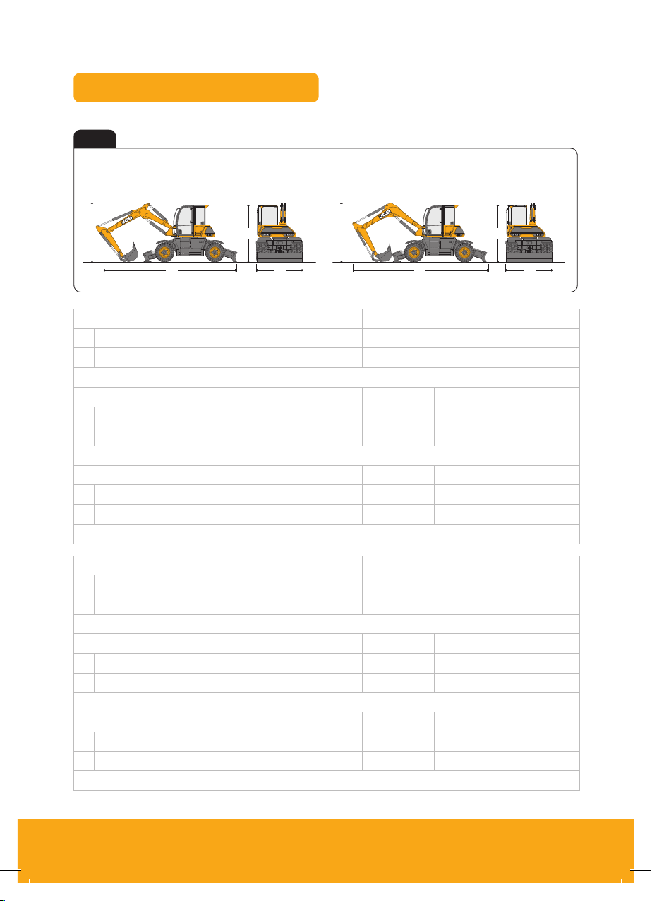
Dimensions
Fig 1
Triple Articulated Boom (TAB) Mono Boom
C C
BB
A ADD
TAB Boom Description Length
A External width over dual wheels mm 2420
B Height over cab mm 2988
Rear Dozer/Front Stabs
Dipper lengths mm 165 0 2000 2250
C Transpor t boom height mm 2988 2988 2988
D Transport length mm 7650 7750 7730
Rear Dozer/No Stabs
Dipper lengths mm 165 0 2000 2250
C Transpor t boom height mm 2988 2988 2988
D Transport length mm 6849 7200 7403
Mass = 10,208kg –11,343kg (plea se see data plate)
MONO Boom Description Length
A External width over dual wheels mm 2420
B Height over cab mm 2988
Rear Dozer/Front Stabs
Dipper lengths mm 165 0 2000 2250
C Transpor t boom height mm 313 2 3305 3437
D Transport length mm 7050 7022 69 44
Rear Dozer/No Stabs
Dipper lengths mm 165 0 2000 2250
C Transpor t boom height mm 2399 2796 3065
D Transport length mm 6868 70 86 7131
Mass = 10,208kg –11,343kg (plea se see data plate)
5
Page 6
Please see operator manual for full details.
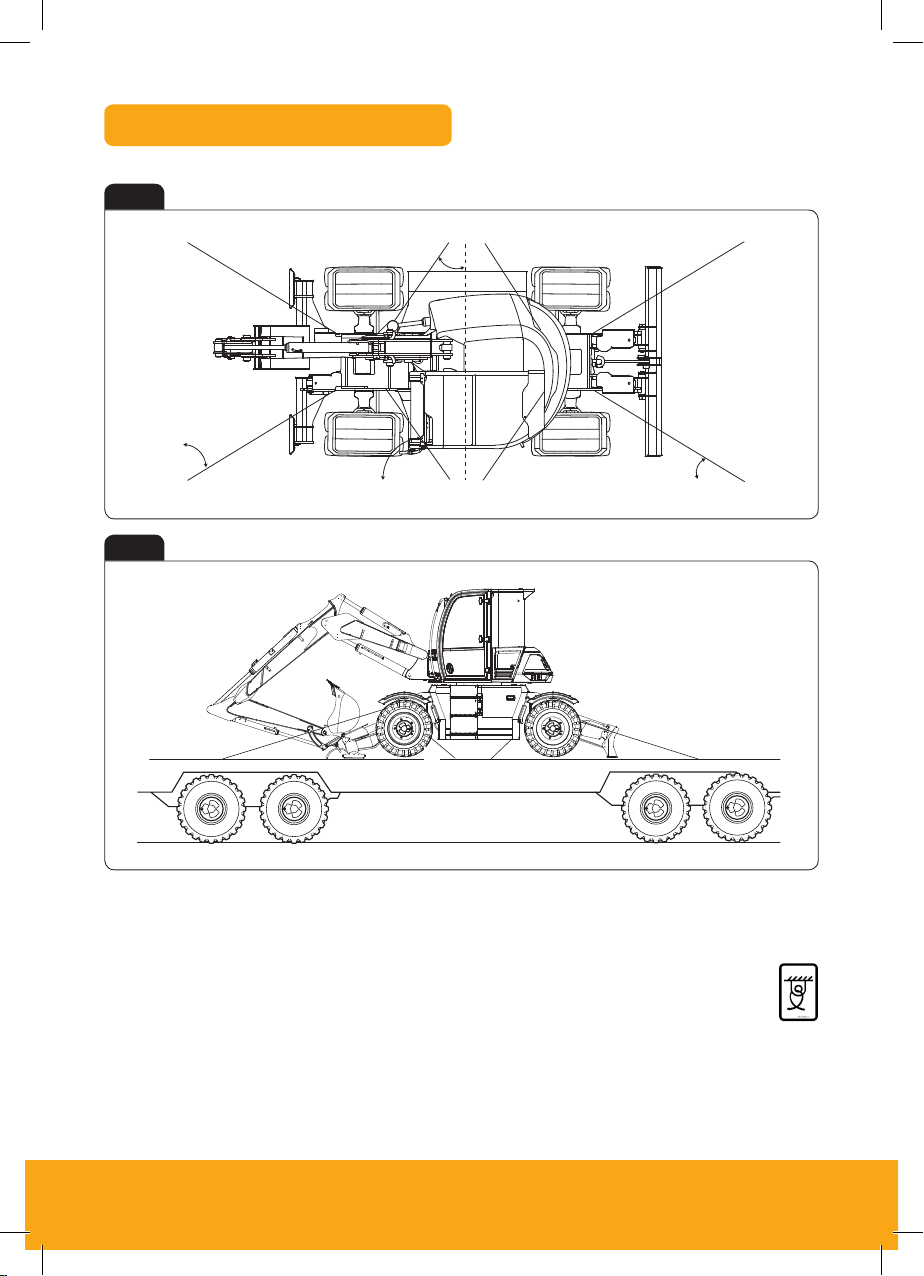
Tie Down Points
E
C
B
F
E
Fig 2
B
Fig 3
F
C
D
A
Note: These measurements are based on a 2500mm wide trailer bed. The correct tie down positions
are identified on the machine by their labels. Measurements ± 100mm.
Tie Down Posi tion Decal
A Angle = 29 ± 1º
B Angle = 45 – 47º
C Angle = 43 – 45º
D Angle = 26 ± 1º
E Angle = 34 – 36º
F Angle = 54 – 56º
6
Page 7
HYDRADIG 110 W
Operation
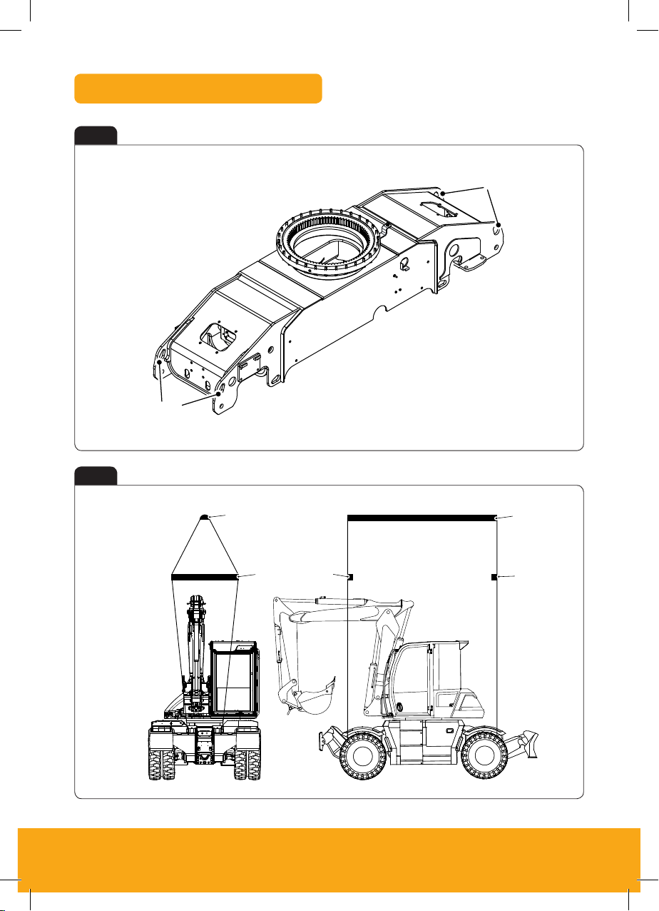
Lifting the Machine
Lifting the Machine
General
The chassis is equipped with 4 lifting points, 2 at the front and 2 at the rear. These points are also used as
tie down points.
The centre of gravity position is approximately 76mm forward of the slew centre, 1,320mm from the ground
and on the machine centre line. It will vary slightly according the position of the upper structure, machine
specification and condition (tyres, fuel level, options, attachment etc)
Figure 82.
A
A
A Lift points
Figure 83. Typical Lifting Arrangement
A
A
Lifting Points
one pair at the rear. These
Figure 80.
A
A
Fig 4
A Lifting points
Fig 5
B Spacer bars
A
B
A
A
B
B
A
B
B
A
7
Page 8

Please see operator manual for full details.
Cab Switch and Panel
About the Product
Operator Station
Operator Station
Component Locations
Figure 12.
V
G
H
J
P
M
Q
R
S
U
L
T
K
N
XF
C
W
Y
Fig 6
A HVAC (Heating Ventilation
Air Conditioning)
B Ignition switch
C Optional switch console
D Switch console
E Fire extinguisher
F Rotary control
G Right joystick
H Stabiliser controls
J Lights and indicators LED
(Light Emitting Diode)s
K 12V socket and USB port
L Instrument panel
M Hazard warning light switch
N Park brake switch
P Throt tle pedal
T
U
V
W
X
A
B
D
E
PQRS
N
M
L
K
J
H
G
F
E
D
Q Brake pedal
R Steering wheel
C
S TAB (Triple Articulated
Boom) pedal
T Multi function switch
U Steering column adjustment
V Steer mode selection
Y
B
A
W Controls isolator lever
X Left joystick
Y Operator seat
Fig 7
A Low flow auxiliaries 1 and 2
B Horn
C Kingpost swing to high-flow auxiliary
changeover
D King post swing / Hi-flow auxiliary
E Forward / Neutral / Reverse
F Site mode: Boom to dozer changeover
Left Hand Joystick Right Hand Joystick
A
A
B
C
F
H
G
Highway mode: Highway override
G One touch idle
H Hammer
8
D
E
Page 9

HYDRADIG 110 W
Rotary Controller & Work Modes
Fig 8
Rotary Controller
B
C
A Home
B Menu access
C Work mode
D Camera
E Scroll / select
F Return
Fig 10
The rotary controller can be used to both control
the machines RPM and to scroll through the menu
A
system on the machine display (dependant on
mode). The rotary can also be used to override
the need to crowd the attachment during the
quick hitch sequence (depressing the enter button)
F
Fig 9
E
D
Work Modes
• Eco
• Standard
• Power (+)
Work modes selection
Press A to cycle through the work modes
Press = Eco Mode – 1600rpm
Press twice = Standard Mode – 1800rpm
Press again = Power (+) Mode – 2000rpm
A
9
Page 10

Please see operator manual for full details.
Switches & Controls
About the Product
Interior Switches
Figure 15.
B
About the Product
Console Switches
Console Switches
Figure 17.
1 3 4 5 62
13 15 16 17 1814
About the Product
Console Switches
13 15 16 17 1814
Fig 11
Keypad 1
A 2 Go
B Quick hitch (opt)
C Side lights
D Front work lights
E Beacon (opt)
F Highway / Site mode
G Axle lock
H Slew lock
J Dipped headlights
Keypad 2
N Auto drive / Creep speed (opt)
P Auto stabilisers up (opt)
Q Lift overload (opt)
R Rear wash / wiper (opt)
S Reversible fan (opt)
T ISO / SAE switchover (opt)
U Reverse steer (opt)
V Front / rear stabilisers (opt)
W Smoothride (opt)
K Rear work lights (opt)
L Rear fog lights
M Radio mute
A
G
X Side worklights (opt)
Y Hand held tool circuit (opt)
Z SCR refresh
N
B
C
D
E
F
H
J
K
L
M
P
Q
R
S
T
Fig 12
Column Switch
A Backwards – Left turn
B Forward – Right turn
C Rotate – Wiper on and off
D Horn
E Upwards – Headlights flash
F Downwards – Main beam
G Windscreen washer
10
U
V
W
X
E
G
F
C
.C
A
A
Y
Z
E
G
D
D
B
F
Page 11

HYDRADIG 110 W
Vehicle & Steering Modes
About the Product
Console Switches
Console Switches
Figure 17.
13 15 16 17 1814
Machine Quick Reference Guide
Machine Quick Reference Guide
Maintenance Position (Excavator Arm Lowered)
1. Park the machine on solid, level ground, with
the upper structure parallel to the
undercarriage.
2. If dozer fitted, lower the blade.
3. Lower the excavator so the dipper is flat on
the ground.
4. Stop the engine.
5. Release the hydraulic pressure and the tank
pressure.
6. Remove the ignition key.
7. Isolate the battery to prevent accidental
operation of the engine (Page 17 Figure 20).
Figure 20
A
A
Excavator lowered with the dipper
flat on the ground
• Site Mode – 20kph
• Highway Mode – 20kph-40kph
Keypad 1:
Press = Highway Mode
Press again = Site mode
(Depends on spec)
Figure 15
Beacon
Highway/
Site Mode
Rear Fog
Lights
Radio
Mute
Fig 13
Park Brake / Hazard Switch
A Park brake switch
B Hazard warning switch
Fig 15
Steering modes
A 4 Wheel steer
B 2 Wheel steer
C Crab steer
Mode selection
Pull the selector and twist it in direction of mode required.
For correct wheel alignment, please select Two Wheel steer (B) when changing between 4 Wheel Steer
and Crab Steer.
A B
A B C
Fig 14
Machine modes
(Machine will default to last used mode)
Site mode – 20Kph Highway mode – 40Kph
Keypad 1
Press = Highway mode
Press again = Site mode
A Beacon (opt)
B Site / Highway mode
C Rear fog lights
D Radio mute
A
B
C
D
11
Page 12

Please see operator manual for full details.
Start Up Sequence
Operation
Safety Equipment
Figure 40.
Operation
Safety Equipment
Figure 40.
Operation
Operating Levers/Pedals
Figure 64.
D
H
B
A
C
About the Product
Console Switches
Console Switches
Figure 17.
1 3 4 5 62
13 15 16 17 1814
About the Product
Console Switches
Console Switches
Figure 17.
1 3 4 5 62
13 15 16 17 1814
1 2 3
Insert Isolator Key
Dis-arm immobiliser Isolate Machine
Insert isolator key (A) and
turn in a clockwise direction.
Key on to position 1 and if
fitted, disarm by entering PIN
Ensure the left arm rest is in
the raised position.
code using the front switch
A
4 65
Start Machine
From ignition position 1 turn
ignition to position 3 (A) to start
the machine.
A
7
Operate Machine
pack on the right hand console.
Lower LH Arm Rest
Lower the LH arm rest to
activate the hydraulics.
A
Start to Drive
Press 2 GO Button
If enabled press 2 GO button
(A) to activate hydraulics.
Instrument panel will illuminate
(B) when active.
A
All controls are now active
and the machine is now
ready to use.
1. Lower LH arm rest (5)
2. Select Gear on RH joystick (Fig 7)
3. Release park brake (Fig 13)
D
E
G
H
4. Release foot brake and press throttle
12
Page 13

HYDRADIG 110 W
Hydraulic Hitch Unlock Sequence
Attachments
Quickhitch
Figure 106.
About the Product
Console Switches
Console Switches
Figure 17.
1 3 4 5 62
13 15 16 17 1814
About the Product
Console Switches
Console Switches
Figure 17.
1 3 4 5 62
13 15 16 17 1814
About the Product
Console Switches
Console Switches
Figure 17.
1 3 4 5 62
13 15 16 17 1814
Standard Attachments
1 2
Start Unlock Process Confirm Process
To start quick hitch unlock
process ensure hydraulics
are live then press quick hitch
Instrument panel will indicate
(A). To confirm process press
2 GO button (B).
sequence button (A).
A
4
Remove Attachment
To disengage the pivot pin
crowd attachment for 3 seconds
then remove attachment.
5
Change Attachment
Operate the machine to engage
the jaw (A) with the attachment
(B) and then full crowd the
attachment to align latch.
A
3
Boom LED Indicator
When the sequence is
confirmed the LED on the
boom will flash red.
A
GO
B
6
Lock Quick Hitch
To engage the lock on the
quick hitch press the quick hitch
button (A). Check attachment
is locked.
A
B
Specialised Attachments
Specialised attachments are any
attachment that when crowded
fully could foul doom/dipper.
When using a specialised
attachment that requires this
process to be followed, replace
4 above with 4a & 4b right,
then continue to follow steps
5 and 6 to finish.
4a
Crowd Override
For large attachments where
crowding is not possible
press & hold rotary dial (A)
for 5 seconds.
A
4b
Remove Attachment
To disengage the pivot pin
operate use the dozer lift lever
(A) until the hitch unlocks then
remove attachment.
A
13
Page 14

Please see operator manual for full details.
Shutdown & Auxiliary Venting
About the Product
Console Switches
Console Switches
Figure 17.
1 3 4 5 62
13 15 16 17 1814
About the Product
Console Switches
Console Switches
Figure 17.
1 3 4 5 62
13 15 16 17 1814
Operation
Entering and Leaving the Operator Station
Operation
Drive Controls
Operation
Slopes
Figure 61.
1
Park Machine
Ensure machine slew is central
and attachment on the ground.
4
Exit Cabin
Switch off all switches. Leave
machine using the handrails
and footholds.
2 3
Apply Foot Brake
Park machine and apply foot
pedal (A) until it locks.
A
Secure Machine
Apply park brake (A) and
disable hydraulics (2 Go) (B).
A
B
Auxiliary Venting
1. Make the machine safe
2. Turn the ignition key to the on position
3. Press and hold 2Go button (A), buzzer will sound
4. Operate controls to lower boom to safe position / auxiliary vent
5. Emergency lowering will last for a short duration
A
14
Emergency Lowering
Black Helmet – Hydraulics isolated
Green Helmet – Hydraulics active
Red Helmet – Emergency lowering. (Press and hold the
2 Go switch (A) for 3 seconds until the red LED illuminates
Page 15

HYDRADIG 110 W
Maintenance Position
Maintenance
Maintenance Positions
Maintenance Positions
Figure 117.
1. Park the machine on solid, level ground
I. Upper structure parallel to the undercarriage
II. Set the hand throttle lever to the idle position
2. Lower the dozer blade (if fitted)
3. Lower the excavator so the attachment is flat on the ground (A)
Fig 16
A
4. Stop the engine
5. Discharge the hydraulic pressure (see aux venting operation)
6. Isolate the controls and remove ignition key
7. Isolate the battery to prevent accidental operation of the engine (Page 16, Fig 17-18)
15
Page 16

Please see operator manual for full details.
Service/Maintenance
Daily Checks (10h) Operator’s Manual Page Ref. Physical/Visual
Tyre pressure check 188 -189 Physical
Wheel nuts alignment check 186 -187 Visual
Tow hitch condition check 74 Visual
Windscreen washer fluid level check/refill 160 Visual
Oil level check 172-173 Physical
Fuel level check 64 Visual
Coolant quality/level check 218 Visual
Coolant or oil leaks check 172 Visual
Park brake – operation check 184 Physical
Oil level check 172-173 Physical
Service brake operation check 184 -185 Physical
Park brake operation check 184 Physical
Brake pressure warning operation check 62 & 171 Physical
Controls isolation safety system operation check 171 Physical
Quickhitch safety system operation check 171 Physic al
Neutral start safety system operation check
Overload warning system operation check
171
171
Physical
Physical
Weekly Checks (50h) Check
Engine filter/sedimenter dr ain/clean
Fuel tank – water & sediment drain
Primar y fuel filter dr ain/clean
Main fuel filter drain/clean
Fuel filler cap check/clean
Radiator clean/check
Pivot & links lubricate
Battery inspect
173
178
181
181
179
108 & 183
165
193
16
Physical
Physical
Physical
Physical
Physical
Physical
Physical
Visual
Page 17

HYDRADIG 110 W
Access Covers
Maintenance
Electrical System
Figure 138.
A
B
Figure 139.
Maintenance
Electrical System
Figure 138.
A
Maintenance
Service Points
Service Points
Figure 118.
E
FA
G
Figure 119.
F
Maintenance
Access Apertures
Access Apertures
Figure 123.
Battery Cover
Fig 17
Fig 18
A Cover B Handle C Lock
Fuses
Fig 19
A Tread plate
B Cover (lower fuses)
A
A
A
A
B
B
C
C
A Air filter
B Batteries
C Hydraulic oil fill
D DEF fill
B
D
C
E
A
F
G
G
Fig 20
A Cover (upper fuses)
B Thumb screw
E Isolator
F Diesel fill
G Mechanical fuel
gauge
D
C
E
B
A
B
B
B
B
A
17
Page 18

Please see operator manual for full details.
Access Covers
Maintenance
Service Points
Service Points
Figure 118.
FA
Maintenance
Service Points
Figure 120.
Maintenance
Access Apertures
Figure 125.
Maintenance
Access Apertures
Figure 124.
C
Cab Panel
Fig 21
A Cover
B Lock
C Window washer fill
Engine Compartment
C
A
A
B
B
A
Fig 22
A
A Cover
B Handle
A
C Lock
D Steps
D
D
B
B
C
Fig 23
A Coolant expansion bottle
B Engine oil fill
C Engine oil dipstick
D Engine oil filter
E Engine fuel filter
F Cooling pack
G Crank case ventilation filter
H Fuel filter / water
H
B
D
C
C
D
B
E
F
E
A
G
G
H
18
Page 19

HYDRADIG 110 W
Fluids & Lubricants
Item Capacity Fluid/lubricant
DEF (Diesel Exhaust Fluid) 19L DEF - - -
Fuel Tank 162L Diesel - - -
JCB Engine Oil UP 5W30 -30°C
(-22°F) to 30°C (86°F)
Engine Oil 14L
Cooling System 28L JCB Antifreeze HP/Coolant 4 0 06/ 112 0 20L
Hydraulic System 19 0L
14. 2L
Differential Axle
Hub Axle (x2) 1.9L (x4) JCB Gear Oil HP Plus 4000/2205 20L -
Transmission Dropbox 1.0L JCB Gear Oil HP Plus 4000/2205 20L -
JCB par t numbers are liable to change and may also var y by region.
For the latest information, always check with your dealer/distributor.
Front &
Rear
JCB Engine Oil UP 5W40 -30°C
(-22°F) to 46°C (115° F)
JCB Engine Oil UP 10W30 -15°C
(-5°F) to 46°C (115°F)
JCB Hydraulic Fluid OP46 4002/2003 20L -
JCB Hydraulic Fluid OP32 4002/2805 20L -
JCB Gear O il HP Plus 4000/2205 20L -
JCB Par t
Number
40 01/3105 20L API C J4
4001/3405 20L API CJ4
4001/3005 20L API CJ4
Container
Size
Spec
ASTM
D6 210
19
Page 20

Please see operator manual for full details.
Machine Attachments
Description
Bucket DP 300mm – 900mm BOT 110 -2 07 Gener al excavation / Bulk loading loose material None
Bucket HD 250mm – 900mm 10 8-210 Heavy Excavation, hard dig, abrasive materials None
Bucket GP 250mm – 900mm 98-17 9 General excavation / Bulk loading loose material None
Bucket – Tilting grading 340 Grading, finishing, landscaping
Bucket – Grading or Ditching
1524mm & 1830mm
Jaw Bucket – 24” 280 General excavation, object handling
Tapered Bucket - 12”/42” & 15”/66” 111- 18 5 Ditching None
Mechanical Quickhitch 101 Quick change of attachments None
Hydraulic Quickhitch - Q uick change of at tachments
Patch Planer 500 Precision removal of road surfaces 1 Hi-Flow aux service
Rock Wheel RW40 -
Compactor -
Ripper Tooth -
Manual Kerb Grab Install Kit 15 Lif ting and positioning kerb-stones up to 70kg None
Manual Rotating Kerb Grab 65 Lifting and positioning kerb-stones up to 70kg
Hydraulic Rotating Kerb Grab 85 Lif ting and posi tioning kerb -stones up to 70kg
Earth Drill 105 Drilling 160mm – 460mm holes 1 Hi-Flow aux service
Hammermaster
HM386Q & HM496Q
Selector Grab SG150 - Demolition, was te handling, sorting
Weight
(kg)
150 &
172
- Breaking up tar mac, concrete, rock 1 Hi-Flow aux service
Grading, finishing, landscaping & ditching None
Accurate cutting and profiling of rock
Intend ed Use
and hard materials
Compac tion of fill and general
ground compaction
Breaking up tarmac, concrete,
hard or frozen ground
Hydraulic
Requirements
1 double acting
aux service
1 double acting
aux service
Quickhitch circuit
and valve
1 Hi-Flow aux service
1 Hi-Flow aux service
None
1 Hi-Flow and
1 Lo-Flow aux service
1 Hi-Flow and
1 Lo-Flow aux service
or 2 Lo-Flow aux
service
1 Hi-Flow and
1 Lo-Flow aux service
or 2 Lo-Flow aux
service
20
Page 21

HYDRADIG 110 W
Troubleshooting/FAQs
Issue / FAQ Resolution/Answer
I can’t select the reverse steer option
I can’t enable Highway mode
Reverse steer can only be operated in site mode. To select the function,
the machine has to be travelling at less than 1kph (Figure 15)
To enable Highway mode:
• The machine must be stationary
• Slew must be centred & controls in neutral
• The machine must not be in reverse steer mode
Why won’t my sta bilisers work?
I have moved the switch but the steer
mode ha sn’t changed
My machine will not st art
Why is there an audible buzzer in the
cab whe n I’m lifting a large load?
I can’t reposition the excavator end
I can’t activate the Hydr aulics
Ensure that the machine hydraulics (2Go) are on and the machine is in site mode
(Figure 11)
For steer mode to change, the machines wheels must align in its central position
(Figure 15)
Ensure the correct start up sequence has been followed as shown previously
(Page 11)
The boom ram pressure ha s exceeded 155bar or the dipper is above
horizont al. The buzzer is a warning
Are you in Highway mode? The excavator end can be overridden by holding
the dozer but ton or AUX on LH Joystick (a buzzer will sounding indicating the
over ride) (Figure 7)
There are many reasons as to why your 2Go may not work when pressing the
button on Keypad 1. Here are some of the following possible reasons:
• If the side pod is lifted and put back down when machine hydr aulics are “on”,
machine hydraulics will disable and not function again until side pod down and
machine in neutral.
• The side pod is in the raised position
• The machine is in Highway mode
• There is a fault on the keypad
• Engine isn’t switched on
• If there is an error on the machine and an error code is displayed on the LCD
screen –which would inhibit the hydraulics
• If none of the above, contac t dealer
21
Page 22

Please see operator manual for full details.
Troubleshooting/FAQs
Issue / FAQ Resolution/Answer
My crab steer won’t select after
using 4WS
You must use 2WS first in order to re-align the rear axles
Why has the over speed warning shown
up on the display
What happens if my machine goes
into “de-r ate”
I can’t enable slew lock
Can I open the Quick Hitch with the
attachment on the ground?
My 40kph machine won’t travel faster
than 20 kph
How do I operate the Quick Hitch?
How do I ena ble the Hand Held Tool
Circuit (HTC)?
The machine has either exceeded 20Kph or 40kph (dependant
on specification). If ignored, machine could go into “de-rate”
The machine speed will be restricted to 25% of the machines capabilit y.
To reset this, key off and on.
In order to enable the slew lock, the slew position sensor must be aligned
with the lower locating pin, in its central position. Alternatively, it could
be a keypad fault.
The Quick Hitch can be opened with the attachment on the ground (when
display prompts to crowd bucket, can press and hold rotary instead to open QH)
Check that site mode is off and Highway mode is selected (Figure 14)
Ensure that the hydraulics (2Go) are activated. Press and hold the Quick Hitch
button on Keypad 1 for two seconds. Acknowledge within 5 seconds by
pressing the “2Go” button. Crowd the bucket ram and stall for two seconds
or depress rotary select. Quick Hitch will release. To complete the process,
when the bucket is safely at tached, press the Quick Hitch button.
Ensure that the hydraulics (2Go) are activated. Press and hold the HTC button
on Keypad 2 until HTC icon is displayed. Once HTC is displayed/activated the
side pod c an be raised, keeping the HTC hydraulics active (work tool must
be connec ted prior to HTC selection)
What does it mean when my axle lock
is on “auto”
22
When the axle lock function is on auto, the machine will lock it’s axles
automatically when the footbrake is on (locked) and will disable once footbrake
is unlocked (for roading purposes).
Page 23

HYDRADIG 110 W
Your Notes
23
Page 24

JCB Sales Limited, Rocester, Staffordshire, United K ingdom ST14 5JP
Tel: +44 1889 590312 Email: salesinfo@jcb.com
Download the very latest information on this product range at: w ww.jcb.com
All right s reserved. No p art of this pub lication may be rep roduced, stored i n a retrieval sys tem, or transmi tted in any form or by any other means, el ectronic, mech anical, photoco pying
or other wise, without p rior permissi on from JCB Sales . All references in t his publicati on to operating wei ghts, sizes, capa cities and other performance m easurements a re provided
for guida nce only and may var y dependant upo n the exact spec ification of the machine. They shou ld not therefore b e relied upon in rel ation to suitab ility for a par ticular applic ation.
Guidance and advice shoul d always be sought f rom your JCB Deale r’. JCB reserves the r ight to change spec ifications wit hout notice. Ill ustrations an d specificatio ns shown may
include op tional equipm ent and accessori es.
9818/3000
 Loading...