

Page 1
TM
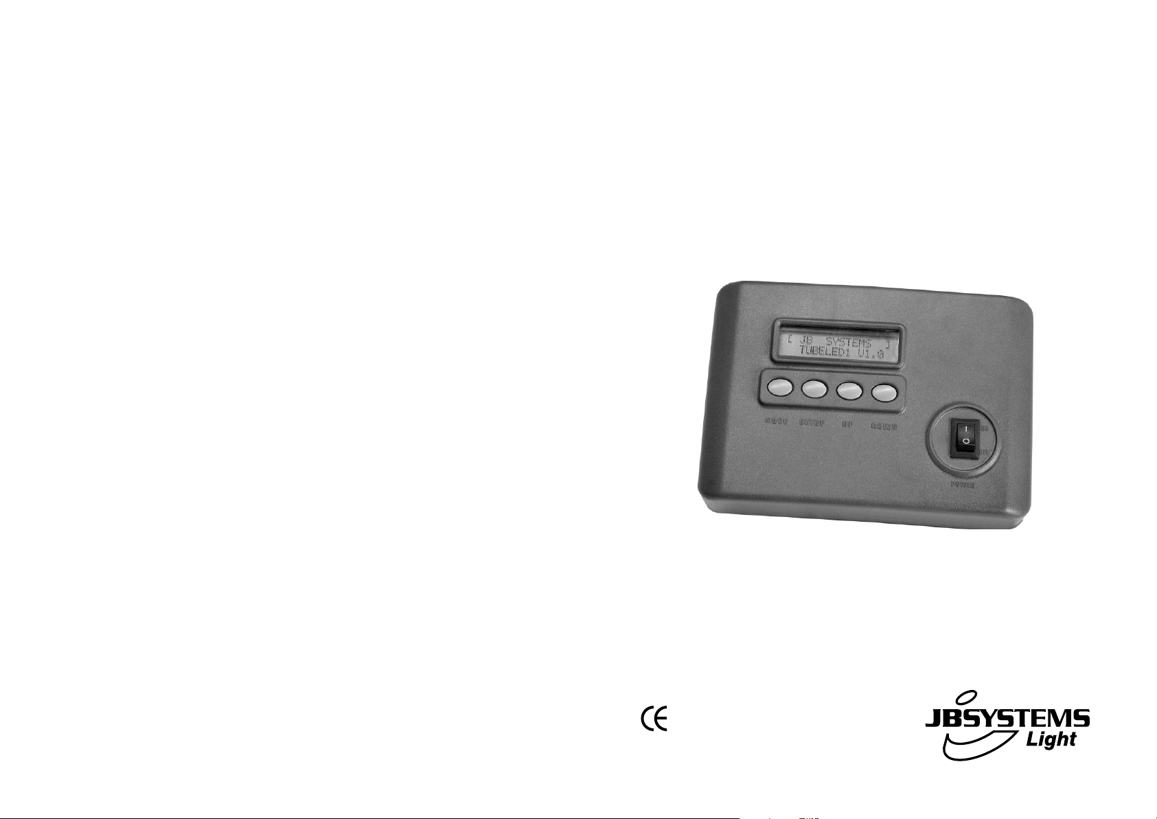
TUBELED
CONTROLLER
FOR INDOOR AND OUTDOOR TUBELEDS
WWW.BEGLEC.COM
Copyright © 2005 by BEGLEC cva.
Reproduction or publication of the content in any manner, without express permission of the publisher, is prohibited.
Version: 1.1
Operation Manual
Mode d'emploi
Gebruiksaanwijzing
Bedienungsanleitung
EN
FR
NL
DU
Page 2

EN - DISPOSAL OF THE DEVICE
Dispose of the unit and used batteries in an environment friendly manner
according to your country regulations.
FR - DÉCLASSER L’APPAREIL
Débarrassez-vous de l’appareil et des piles usagées de manière écologique
Conformément aux dispositions légales de votre pays.
NL - VERWIJDEREN VAN HET APPARAAT
Verwijder het toestel en de gebruikte batterijen op een milieuvriendelijke
manier conform de in uw land geldende voorschriften.
DU - ENTSORGUNG DES GERÄTS
Entsorgen Sie das Gerät und die Batterien auf umweltfreundliche Art und
Weise gemäß den Vorschriften Ihres Landes.
ES - DESHACERSE DEL APARATO
Reciclar el aparato y pilas usadas de forma ecologica conforme a las
disposiciones legales de su pais.
PT - COMO DESFAZER-SE DA UNIDADE
Tente reciclar a unidade e as pilhas usadas respeitando o ambiente e em
conformidade com as normas vigentes no seu país.
Page 3
ENGLISH OPERATION MANUAL
OPERATION MANUAL
Thank you for buying this JB Systems product. To take full advantage of all
possibilities, please read these operating instructions very carefully.
The JB Systems TUBELED™ system contains the following components:
• The 1m long TUBELED™ tubes: to be connected to the controller.
• The TUBELED™ controller: controls the connected led tubes.
• Signal extension cables: 5m or 10m.
• Power extension cables: 5m, 10m or 20m.
This manual only explains the functions of the controller.
FEATURES
• Dedicated controller used to control the TUBELED™ led tubes (not included)
• Controls up to 4000 tubes, no extra power boosters needed.
• 38 preprogrammed patterns
• Auto mode scans all patterns automatically
• Pattern selection by DMX512:
o Channel1: choose patterns
o Channel2: speed control
o Channel3: interval time
o Channel4: strobe/flash rate
• RGB color mixing, controlled by DMX512 (make your own colors):
o Channel1: not used (set to zero)
o Channel2: dimming red color
o Channel3: dimming green color
o Channel4: dimming blue color
• Adjustable strobe function
• Adjustable speed and interval time for most patterns
• Nice plastic enclosure can be fixed on the wall
• Auto save function: saves the last working mode for all patterns individually.
• Perfect for use in: retail stores, commercial displays, architectural lighting, indoor
and outdoor decoration, clubs, pubs, mobile DJs, trussing, …
ENGLISH OPERATION MANUAL
Some important instructions:
• To protect the environment, please try to recycle the packing material as much as
possible.
• Keep this booklet in a safe place for future consultation. If you sell this product, be
sure to add this user manual.
• To prevent fire or shock hazard, do not expose this appliance to rain or moisture.
• Install the unit always indoor!
• Don’t place metal objects or spill liquid inside the unit. Electric shock or malfunction
may result. If a foreign object enters the unit, immediately disconnect the mains
power.
• Prevent use in dusty environments and clean the unit regularly.
• The electrical installation should be carried out by qualified personal.
• We strongly suggest NOT opening the cover, there are no user serviceable parts
inside.
• In the event of serious operating problems, stop using the controller and contact your
dealer immediately.
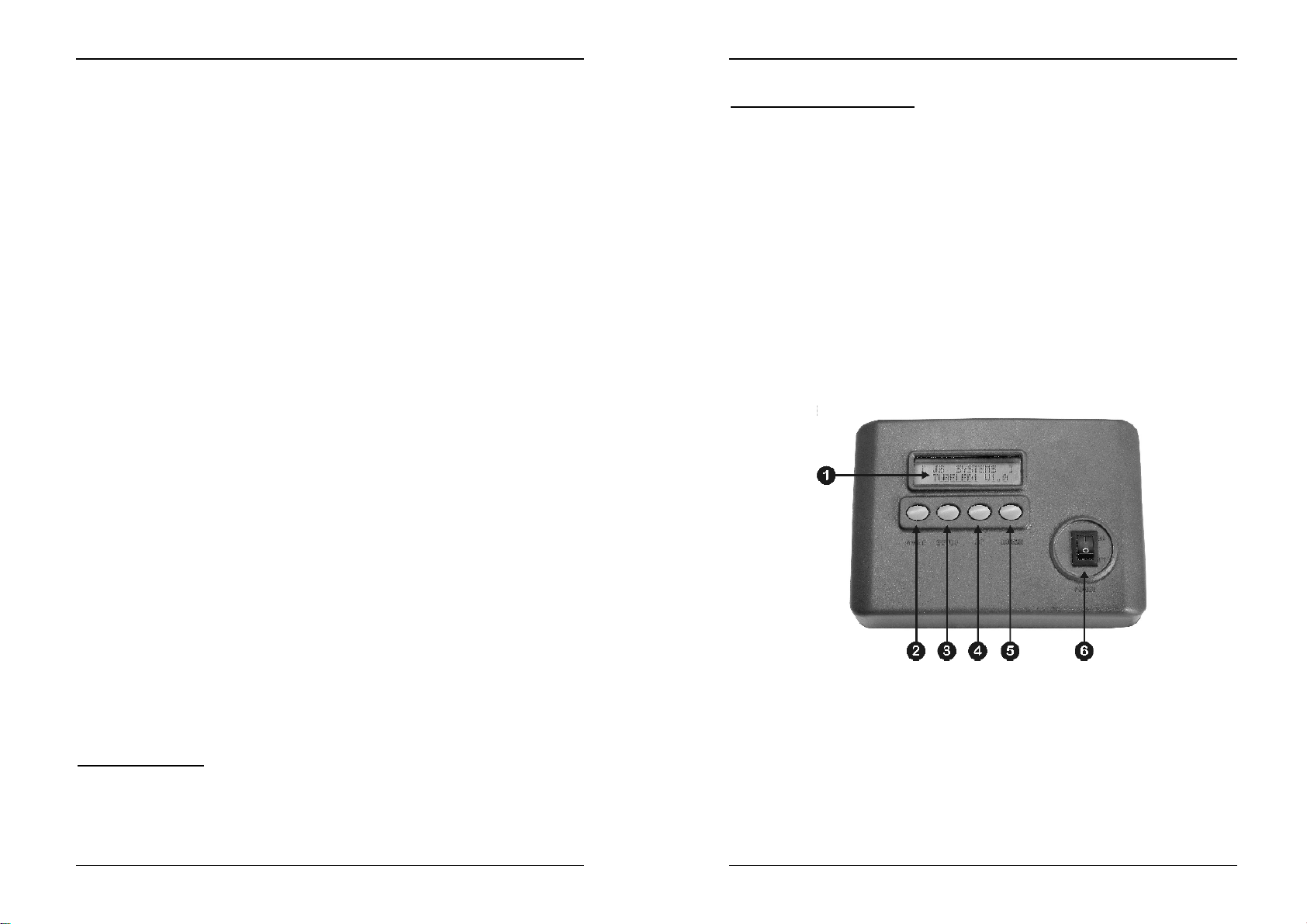
CONTROLS (FRONT)
1. LCD DISPLAY: shows you all necessary information about working mode,
2. MODE BUTTON: used to choose the desired working mode and patterns. The
BEFORE USE
Check the contents:
Check if the carton contains the following items:
• TUBELED™ controller
• Mains DC Adapter 12V 500mA
• Operating instructions
JB SYSTEMS 1/29 TUBELED™ CONTROLLER
3. SETUP BUTTON: used to set the parameters of the selected mode or pattern.
JB SYSTEMS 2/29 TUBELED™ CONTROLLER
parameters etc.
display shows another function every time you push the button. Keep the button
pressed if you want to browse faster through all possible modes. (see further for
the possible options to choose from)
Almost every pattern can have its own parameters. These parameters are saved
for every pattern individually.
y Interval: this is the waiting time between two steps in a chase pattern.
Page 4
ENGLISH OPERATION MANUAL
With the UP/DOWN buttons you can select a value between 000 and 100.
(000 = short interval time * 100 = longer interval time)
Press SETUP again to confirm the selected parameter.
y Speed: this is the speed of the chase pattern.
With the UP/DOWN buttons you can select a value between 000 and 100.
(000 = low speed * 100 = high speed)
Press SETUP again to confirm the selected parameter.
y Flash: here you can select the strobe or flash rate of the TUBELED™.
With the UP/DOWN buttons you can select a value between 000 and 100.
(000 = no strobe function * 100 = high flash rate)
Press SETUP again to confirm the selected parameter.
y Tube: used to set the number of TUBELED™ tubes connected to the
controller. You only need to setup the number of tubes once. Most of the
patterns won’t work properly when the number of connected tubes doesn’t
correspond to the selected number on the controller.
Remark:
4. UP BUTTON: used to choose a higher value for the selected parameter.
5. DOWN BUTTON: used to choose a lower value for the selected parameter.
6. POWER ON/OFF: Used to switch the controller on and off. The last working mode
is saved when the controller is switched off.
The setup function is not available on all patterns or working modes.
ENGLISH OPERATION MANUAL
INSTALLATION STEPS:
To be sure that the TUBELED™ system works properly you must follow the
steps below every time you change the number of tubes, put tubes at different
locations or simply disconnect en reconnect one or more tubes:
• INSTALL ALL TUBES: Refer to the installation manual included with each
TUBELED™ for proper installation.
• INSTALL THE CONTROLLER:
• TEST CONNECTIONS: we will test the connection between the controller and the
led tubes.
• SET THE NUMBER OF TUBELEDS: To be able to produce nice programs, the
controller needs to know how many tubeleds are connected.
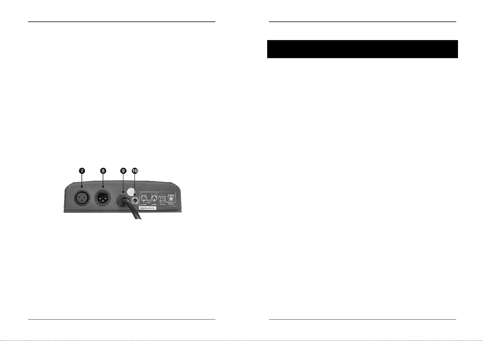
CONNECTIONS (REAR)
Remark: If the number of connected tubes doesn’t match the number set on the controller, the
system will not work properly. Some tubes will even not work at all!
• PROPER ADDRESSING: automatically sets the addresses of the connected tubes.
Perform this action always when you connect a different number of tubes:
At this point the setup is finished if you use the TUBELED™ system in standalone
7. DMX INPUT: The TUBELED™ controller only receives DMX signals so it must be
connected as any other light effect in the DMX line. The 3pin male XLR-connector
receives instructions from any universal DMX-controller. In the next chapter we
explain how to set up the DMX addresses.
8. DMX OUTPUT: The 3pin female XLR-connector is used to connect the controller
with the next unit in the DMX chain.
9. TUBELED SIGNAL CABLE: connect this cable to the first led tube in the chain.
Extra 5m or 10m signal cable extensions are optionally available.
10. DC POWER INPUT: Used to connect the supplied 12V / 500mA DC adapter to the
controller.
mode. Look further on how to use the DMX capabilities.
• DMX512 ADDRESSING: Before using the DMX capabilities you have to set the
starting address:
• FACTORY SETTINGS: As explained before you can set and save different
parameters for all patterns. You can set all parameters back to the factory settings.
Attention: Note that all your previous settings will be lost:
o Put the controller in a suitable place. Eventually you can fix the controller to
the wall.
o Connect the supplied DC adapter to the controller
o Connect the signal output to the signal input of first led tube.
o Switch the controller on
o Use the MODE button to select “test mode”
o Press the SETUP button. (display shows “Connection OK if tubes are red”)
As the display states: if all led tubes are “red”, the connections are OK.
o Go to any of the “non static” patterns.
o Press the setup button until the display shows “Tubes : 0000”
o Use the up and down buttons to set the exact number of connected tubes.
o Press the setup button again to confirm.
o Use the MODE button to select “address mode”
o Press the SETUP button. During the initializing process the display shows
“initializing addr. Waiting…” When the initializing is done, the display shows
“OK! Address is done”
o Use the MODE button to select “DMX512 Mode”
o Press the SETUP button. The display shows the current DMX starting
address.
o With the UP/DOWN buttons you can select the desired DMX starting
address. (starting addresses up to 255 can be selected)
o Press the SETUP button again to confirm the selected starting address.
o Use the MODE button to select “Factory settings” on the display.
JB SYSTEMS 3/29 TUBELED™ CONTROLLER
JB SYSTEMS 4/29 TUBELED™ CONTROLLER
Page 5
ENGLISH OPERATION MANUAL
o Press the SETUP button to load the factory settings. The display shows
“OK! Setting is done”
STANDALONE MODE:
This is the simplest way to operate the TUBELED™ system.
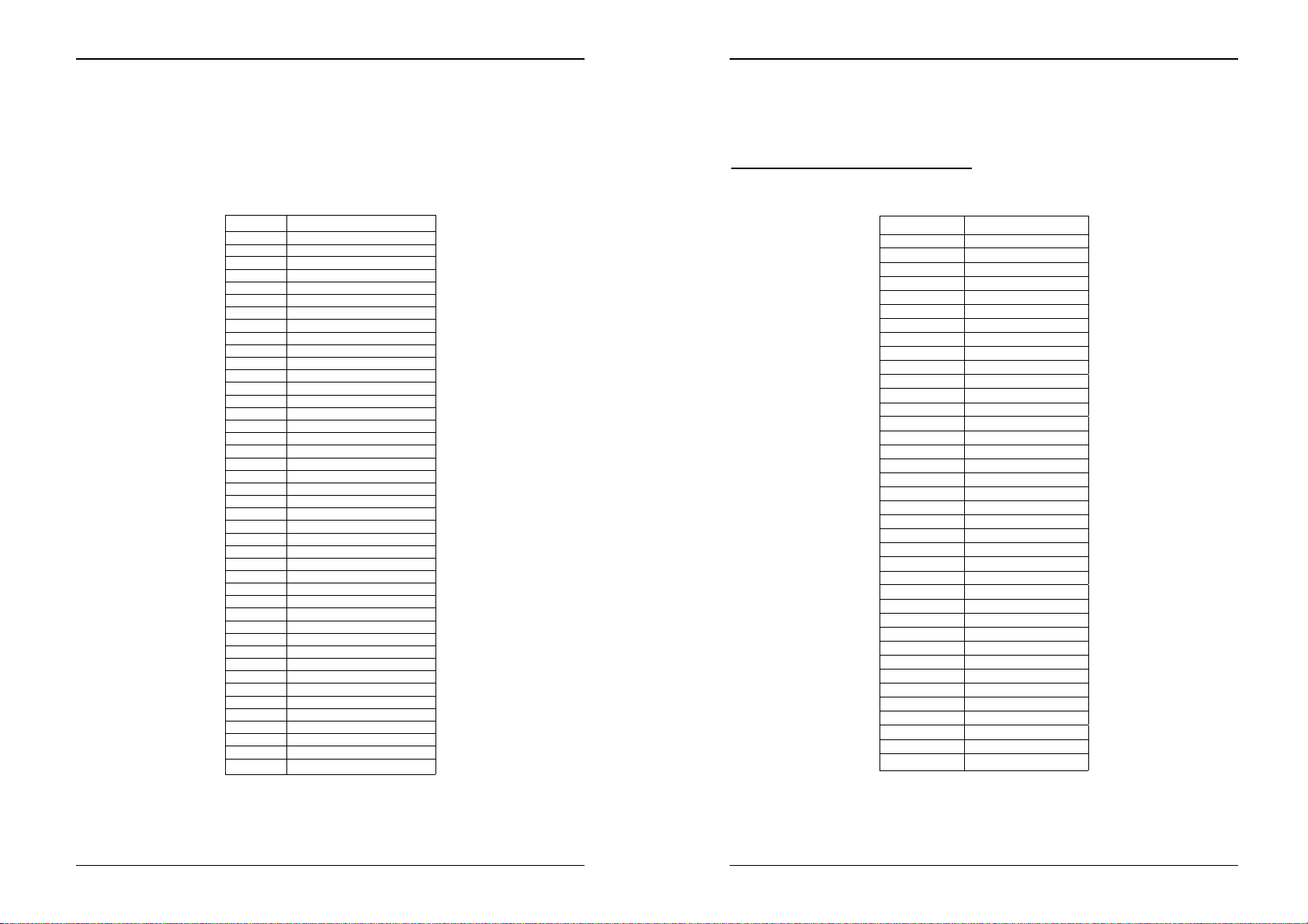
Use the MODE button to select the desired mode or patterns from the list below:
Use the SETUP and UP/DOWN buttons to change the values of the pattern
Number PATTERN / MODE
1 BLACKOUT
2 STATIC RED
3 STATIC GREEN
4 STATIC YELLOW
5 STATIC BLUE
6 STATIC PURPLE
7 STATIC CYAN
8 STATIC WHITE
9 FAST CHANGE
10 SLOW FLOW 1
11 FAST FL O W 1
12 FAST FLOW 2
13 BLACK RUN 1
14 ROLL CHASE
15 ROLL COLOR
16 COLOR 1/4
17 COLOR1 1/4
18 COLOR 1/2
19 COLOR FLASH
20 B & W FLOW
21 R & G FLOW
22 G & B FLOW
23 R & B FLOW
24 R & G CHASE 1
25 R & G CHASE 2
26 R & B CHASE 1
27 R & B CHASE 2
28 R & W CHASE 1
29 R & W CHASE 2
30 B & G CHASE 1
31 B & G CHASE 2
32 W &G CHASE 1
33 W &G CHASE 2
34 RAINBOW CHASE 1
35 RAINBOW CHASE 2
36 RAINBOW CHASE 3
37 RAINBOW CHASE 4
38 RAINBOW CHASE 8
39 AUTO MODE
40 TEST MODE
41 ADDRESS MODE
42 Factory settings load
43 DMX512 MODE
ENGLISH OPERATION MANUAL
DMX-512 MODE:
Before using the DMX capabilities you have to set the start address. See “installation
steps”. There are two different ways to control the controller by DMX:
MODE1 – DMX PATTERN SELECTION:
Mode1 is active when the DMX value of channel1 is not zero!
• Channel1 is used select one of the preprogrammed patterns:
• Channel2 is used to control the pattern speed:
parameters. Refer to the “CONTROLS (front)” section to read more about how to use
these buttons.
JB SYSTEMS 5/29 TUBELED™ CONTROLLER
JB SYSTEMS 6/29 TUBELED™ CONTROLLER
DMX Value Pattern
1~5 BLACKOUT
6~11 STATIC RED
12~17 STATIC GREEN
18~23 STATIC YELLOW
24~29 STATIC BLUE
30~35 STATIC PURPLE
36~41 STATIC CYAN
42~47 STATIC WHITE
48~53 FAST CHANGE
54~59 SLOW FLOW1
60~65 FAST FLOWI
66~71 FAST FLOW2
72~77 BLACK RUNT
78~83 ROLL CHASE
84~89 ROLL COLOR
90~95 COLOR 1/4
96~101 COLOR1 1/4
102~107 COLOR1 ½
108~113 COLOR FLASH
114~119 B & W FLOW
120~125 R & G FLOW
126~131 G & B FLOW
132~137 R & B FLOW
138~143 R & G CHASE 1
144~149 R & G CHASE 2
150~155 R & B CHASE 1
156~161 R & B CHASE 2
162~167 R & W CHASE 1
168~173 R & W CHASE 2
174~179 B & G CHASE 1
180~185 B & G CHASE 2
186~191 W &G CHASE 1
192~197 W &G CHASE 2
198~203 RAINBOW CHASE 1
204~209 RAINBOW CHASE 2
210~215 RAINBOW CHASE 3
216~221 RAINBOW CHASE 4
222~255 RAINBOW CHASE 8
DMX value = 000 Æ Speed = 0
DMX value = 255 Æ Speed = maximum
Page 6
ENGLISH OPERATION MANUAL
• Channel3 is used to control the interval time:
• Channel4 is used to control the flash (strobe) rate:
Remark: note that channels 2 and 3 (speed and interval) have no effect on the blackout and static
colors (DMX value for channel1 is between 1 and 47).
MODE2 – RGB COLOR MIXING:
Mode2 is active when the DMX value of channel1 is zero!
• Channel1 is not used and must be set to zero.
• Channel2 is used to dim the RED colored leds inside the tubes:
• Channel3 is used to dim the GREEN colored leds inside the tubes:
• Channel4 is used to dim the BLUE colored leds inside the tubes:
DMX value = 000 Æ Interval time = 0
DMX value = 255 Æ Interval time = maximum
DMX value = 000 Æ Interval time = 0
DMX value = 255 Æ Interval time = maximum
DMX value = 000 Æ no red light output
DMX value = 255 Æ maximum red light output
DMX value = 000 Æ no green light output
DMX value = 255 Æ maximum green light output
DMX value = 000 Æ no blue light output
DMX value = 255 Æ maximum blue light output
FRANCAIS MODE D’EMPLOI
MODE D’EMPLOI
Nous vous remercions d’avoir acheté ce produit JB Systems. Veuillez lire ce mode
d’emploi attentivement afin de pouvoir exploiter correctement toutes les possibilités de
cet appareil
Le système JB Systems TUBELED™ est composé des éléments suivants:
• Les tubes TUBELED™ d’1m de long: a connecter au contrôleur.
• Le contrôleur TUBELED™: commande les tubes connectés.
• Des câbles rallonge du Signal: 5m ou 10m.
• Des câbles rallonge d’alimentation: 5m, 10m ou 20m.
Ce mode d’emploi explique uniquement comment utiliser le contrôleur.
CARACTERISTIQUES
• Contrôleur spécifique pour commander les tubes TUBELED™ (non compris)
• Peut commander jusqu’à 4000 tubes, ne nécessite pas de modules d’alimentation
SPECIFICATIONS
Mains Input: DC Adapter 230V/50Hz Æ 12Vdc / 500mA
Preprogrammed patterns: 38
Max. number of tubes: up to 4000pcs.
DMX connections: 3pin XLR male / female
DMX addressing: 000 to 255
Power consumption: <1.5Watt
Size: 180 x 125 x 49mm
Weight: 0.4 kg
• 38 programmes préprogrammés
• La fonction Auto parcourt automatiquement tous les programmes.
• Sélection du programme par DMX512:
• Mixage des couleurs RVB, contrôlé par DMX512 (créez vos propres couleurs):
• Fonction stroboscopique réglable
• Vitesse et temps d’intervalle réglable pour la plupart des programmes
• Beau boîtier en plastique qui peut être fixé au mur
• Fonction de sauvegarde automatique: sauvegarde du mode de fonctionnement
• Convient parfaitement pour: des magasins, des étalages, l’éclairage architectural,
supplémentaires.
o Canal1: choix des programmes
o Canal2: contrôle de la vitesse
o Canal3: temps d’intervalle
o Canal4: vitesse stroboscope/flash
o Canal1: n’est pas utilisé (réglé sur zéro)
o Canal2: atténuation de la couleur rouge
o Canal3: atténuation de la couleur verte
o Canal4: atténuation de la couleur bleue
pour tous les programmes (patterns) individuellement.
la décoration intérieure et extérieure, les clubs, tavernes, disco mobile, dans les
structures de pont, …
JB SYSTEMS 7/29 TUBELED™ CONTROLLER
JB SYSTEMS 8/29 TUBELED™ CONTROLLER
Page 7

FRANCAIS MODE D’EMPLOI
AVANT L’UTILISATION
Contrôlez le contenu:
Vérifiez si la boite contient les éléments suivants:
• Le contrôleur TUBELED™
• Adaptateur d’alimentation DC 12V 500mA
• Mode d’emploi
Quelques instructions importantes:
• Afin de protéger l’environnement, essayez de recycler le plus possible les matériaux
d’emballage.
• Conservez ce mode d’emploi dans un endroit sûr afin de pouvoir le consulter
ultérieurement. Si vous vendez cet appareil, ajoutez-y toujours ce mode d’emploi.
• Afin d'éviter tout risque d'électrocution ou d'incendie, n'exposez pas l’amplificateur à
la pluie ou à l'humidité.
• Installez toujours cet appareil à l’intérieur!
• N’insérez jamais d’objets métalliques et ne renversez jamais de liquide dans
l’appareil. L’électrocution ou le disfonctionnement peuvent en résulter. Si un objet
étranger entre dans l’appareil, débranchez immédiatement l’alimentation
• Evitez une utilisation dans des endroits poussiéreux et nettoyez l’appareil
régulièrement.
• L’installation électrique doit être exécuté par des personnes qualifiées
• Il est fortement recommandé de NE PAS ouvrir l’appareil, Il n’y à aucune pièce à
l’intérieur de l’appareil que vous pouvez remplacer vous-même.
• Si de sérieux problèmes de fonctionnement devaient se produire, arrêtez d’utiliser le
contrôleur et prévenez immédiatement votre revendeur.
FRANCAIS MODE D’EMPLOI
1. ECRAN LCD: affiche toutes les informations utiles du mode de fonctionnement,
2. Touche MODE: est utilisée pour sélectionner le mode de fonctionnement et les
3. Touche SETUP: est utilisée pour régler les paramètres du mode de
CONTROLES (FACE AVANT)
4. Touche UP: est utilisée pour attribuer une plus grande valeur au paramètre
5. Touche DOWN: est utilisée pour attribuer une plus petite valeur au paramètre
6. POWER ON/OFF: Est utilisé pour allumer ou éteindre le contrôleur. Quand vous
des paramètres, etc.
programmes (patterns) désirés. L’écran affiche une autre fonction chaque fois que
vous appuyez sur la touche. Tenez la touché enfoncée si vous désirez parcourir
plus rapidement tous les modes de fonctionnement qui sont disponibles. (voyez
plus loin pour voir toutes les options possibles)
fonctionnement ou du programme sélectionné. A peu près chaque programme
peut avoir ses propres paramètres. Ces paramètres sont sauvegardés pour
chaque programme (pattern) séparément.
y Interval: ceci est le temps d’attente entre deux pas dans un programme du
type chenillard (chase).
A l’aide des touches UP/DOWN vous pouvez sélectionner une valeur située
entre 000 et 100. (000 = courte durée d’intervalle * 100 = longue durée
d’intervalle)
Appuyez à nouveau sur la touche SETUP pour confirmer le paramètre
sélectionné.
y Speed: ceci est la vitesse du programme chenillard (chase pattern).
A l’aide des touches UP/DOWN vous pouvez sélectionner une valeur située
entre 000 et 100. (000 = lent * 100 = rapide)
Appuyez à nouveau sur la touche SETUP pour confirmer le paramètre
sélectionné.
y Flash: ici vous pouvez sélectionner la fréquence du stroboscope ou du flash
du TUBELED™.
A l’aide des touches UP/DOWN vous pouvez sélectionner une valeur située
entre 000 et 100. (000 = pas de fonction stroboscopique * 100 = haute
fréquence du flash)
Appuyez à nouveau sur la touche SETUP pour confirmer le paramètre
sélectionné.
y Tube: est utilisé pour spécifier le nombre de tubes TUBELED™ qui sont
connectés à votre contrôleur. Vous ne devez spécifier le nombre de tubes
qu’une seule fois. La plupart des programmes ne fonctionneront pas
correctement si le nombre de tubes connectés ne correspond pas au
nombre sélectionné dans le contrôleur.
Remarque:
fonctionnement.
sélectionné.
sélectionné.
éteignez le contrôleur, le dernier mode de fonctionnement sera sauvegardé
automatiquement.
La fonction setup n’est pas disponible pour tous les programmes ou tous les modes de
JB SYSTEMS 9/29 TUBELED™ CONTROLLER
JB SYSTEMS 10/29 TUBELED™ CONTROLLER
Page 8

FRANCAIS MODE D’EMPLOI
FRANCAIS MODE D’EMPLOI
CONNECTIONS (ARRIERE)
• ADRESSAGE ADEQUAT: règle automatiquement les adresses des tubes
7. ENTREE DMX: Le contrôleur TUBELED™ reçoit uniquement des signaux DMX et
doit donc être connecté comme chaque autre effet dans la ligne DMX. Le
connecteur XLR male à 3 pôles reçoit les instructions de n’importe quel contrôleur
DMX universel. Au chapitre suivant nous-vous expliquons comment attribuer les
adresses DMX.
8. SORTIE DMX: Le connecteur XLR femelle à 3 pôles est utilisé pour connecter le
contrôleur au prochain appareil dans la chaîne DMX.
9. CABLE DU SIGNAL TUBELED: connectez ce câble au premier tube Led dans la
chaîne. Des câbles rallonge de 5m ou 10m sont disponibles en option.
10. DC POWER INPUT: Est utilisé pour connecter l’adaptateur d’alimentation 12V /
500mA DC, fourni avec le contrôleur.
INSTALLATION PAS PAR PAS:
Pour être sûr que votre installation TUBELED™ fonctionne correctement
vous devez suivre les étapes ci-dessous chaque fois que vous changez le
nombre de tubes, changez les tubes de place ou simplement débranchez et
rebranchez 1 ou plusieurs tubes:
• INSTALLEZ TOUS LES TUBES: Référez-vous au manuel d’installation fourni avec
chaque TUBELED™ afin d’assurer une installation correcte.
• INSTALLEZ LE CONTROLEUR:
o Installez le contrôleur à un endroit approprié. Vous pouvez éventuellement
fixer le contrôleur au mur.
o Connectez l’adaptateur d’alimentation au contrôleur.
o Connectez la sortie du signal à l’entrée signal du premier tube led.
• TESTEZ LES CONNEXIONS: nous testerons la connexion entre le contrôleur et les
tubes led.
o Allumez le contrôleur
o Utilisez la touche MODE pour sélectionner “test mode”
o Appuyez sur la touche SETUP. (l’écran affiche “Connection OK if tubes are
red”) Si cela est affiché et que tous les tubes sont effectivement rouges, les
connexions sont correctes.
• SPECIFIEZ LE NOMBRE DE TUBELEDS: Pour être capable de produire de beaux
programmes, le contrôleur doit savoir combien de tubeleds sont relies ensemble.
o Choisissez un programme “non statique”.
A ce stade, l’installation est terminée si vous désirez utilisez le système TUBELED™
de façon autonome. Voyez plus loin comment utiliser les possibilités DMX.
• ADRESSAGE DMX512: Avant de pouvoir exploiter les possibilités DMX vous devez
• REGLAGES D’USINE: Comme expliqué auparavant, vous pouvez régler et
o Appuyez sur la touche setup jusqu’à ce que l’écran affiche “Tubes: ….”
o Utilisez les touches up et down pour spécifier le nombre exact de tubes
connectés
o Appuyez à nouveau sur la touche setup pour confirmer.
Remarque: Si le nombre de tubes connectés ne correspond pas au nombre introduit dans le
contrôleur, le système ne fonctionnera pas correctement. Certains tubes peuvent même ne pas
fonctionner du tout !
connectés. Exécutez cette action chaque fois que vous connectez un nombre
différent de tubes:
o Utilisez la touche MODE pour sélectionner “address mode”
o Appuyez sur la touche SETUP. Pendant le processus d’initialisation, l’écran
affiche “initializing addr. Waiting…” Quand l’initialisation est terminée,
l’écran affiche “OK! Address is done” (adressage terminé)
définir l’adresse de départ:
o Utilisez la touche MODE pour sélectionner “DMX512 Mode”
o Appuyez sur la touche SETUP. L’écran affiche l’adresse de départ DMX
actuel.
o Vous pouvez sélectionner l’adresse DMX de départ désirée en utilisant les
touches UP/DOWN. (une adresse de départ jusqu’à 255 peut être
sélectionnée)
o Appuyez à nouveau sur la touche SETUP pour confirmer l’adresse de
départ sélectionnée.
sauvegarder différents paramètres pour tous les programmes. Vous pouvez
également réinstaller tous les paramètres selon le réglage d’usine. Attention: tous
vos réglages précédents seront perdus:
o Utilisez la touche MODE pour sélectionner “Factory settings” sur l’écran.
o Appuyez sur la touche SETUP pour charger les réglages d’usine. L’écran
affiche “OK! Setting is done”
JB SYSTEMS 11/29 TUBELED™ CONTROLLER
JB SYSTEMS 12/29 TUBELED™ CONTROLLER
Page 9

FRANCAIS MODE D’EMPLOI
FRANCAIS MODE D’EMPLOI
FONCTIONNEMENT AUTONOME:
Ceci est la façon la plus simple pour faire fonctionner le système TUBELED™.
Utilisez la touche MODE pour sélectionner le mode de fonctionnement ou le
programme désiré de la liste ci-dessous:
Utilisez les touches SETUP et UP/DOWN pour changer la valeur des paramètres du
programme. Référez-vous au chapitre “CONTROLES (face avant)” pour savoir
comment utiliser ces touches.
JB SYSTEMS 13/29 TUBELED™ CONTROLLER
Number PATTERN / MODE
1 BLACKOUT
2 STATIC RED
3 STATIC GREEN
4 STATIC YELLOW
5 STATIC BLUE
6 STATIC PURPLE
7 STATIC CYAN
8 STATIC WHITE
9 FAST CHANGE
10 SLOW FLOW 1
11 FAST FL O W 1
12 FAST FLOW 2
13 BLACK RUN 1
14 ROLL CHASE
15 ROLL COLOR
16 COLOR 1/4
17 COLOR1 1/4
18 COLOR 1/2
19 COLOR FLASH
20 B & W FLOW
21 R & G FLOW
22 G & B FLOW
23 R & B FLOW
24 R & G CHASE 1
25 R & G CHASE 2
26 R & B CHASE 1
27 R & B CHASE 2
28 R & W CHASE 1
29 R & W CHASE 2
30 B & G CHASE 1
31 B & G CHASE 2
32 W &G CHASE 1
33 W &G CHASE 2
34 RAINBOW CHASE 1
35 RAINBOW CHASE 2
36 RAINBOW CHASE 3
37 RAINBOW CHASE 4
38 RAINBOW CHASE 8
39 AUTO MODE
40 TEST MODE
41 ADDRESS MODE
42 Factory settings load
43 DMX512 MODE
FONCTIONNEMENT DMX-512:
Avant d’utiliser les possibilités DMX vous devez régler l’adresse de départ. Voir
“installation pas par pas”. Il y a 2 différentes façons pour commander le contrôleur par
DMX :
MODE1 – SELECTION DES MODELES PAR DMX:
Mode1 est actif quand la valeur DMX du canal 1 n’est pas réglée sur zéro!
• Canal1 est utilise pour sélectionner un des programmes préprogrammés:
DMX Value Pattern
1~5 BLACKOUT
6~11 STATIC RED
12~17 STATIC GREEN
18~23 STATIC YELLOW
24~29 STATIC BLUE
30~35 STATIC PURPLE
36~41 STATIC CYAN
42~47 STATIC WHITE
48~53 FAST CHANGE
54~59 SLOW FLOW1
60~65 FAST FLOWI
66~71 FAST FLOW2
72~77 BLACK RUNT
78~83 ROLL CHASE
84~89 ROLL COLOR
90~95 COLOR 1/4
96~101 COLOR1 1/4
102~107 COLOR1 ½
108~113 COLOR FLASH
114~119 B & W FLOW
120~125 R & G FLOW
126~131 G & B FLOW
132~137 R & B FLOW
138~143 R & G CHASE 1
144~149 R & G CHASE 2
150~155 R & B CHASE 1
156~161 R & B CHASE 2
162~167 R & W CHASE 1
168~173 R & W CHASE 2
174~179 B & G CHASE 1
180~185 B & G CHASE 2
186~191 W &G CHASE 1
192~197 W &G CHASE 2
198~203 RAINBOW CHASE 1
204~209 RAINBOW CHASE 2
210~215 RAINBOW CHASE 3
216~221 RAINBOW CHASE 4
222~255 RAINBOW CHASE 8
• Canal2 est utilise pour contrôler la vitesse du programme:
Valeur DMX = 000 Æ Vitesse = 0
Valeur DMX = 255 Æ Vitesse = maximale
JB SYSTEMS 14/29 TUBELED™ CONTROLLER
Page 10

FRANCAIS MODE D’EMPLOI
• Canal3 est utilisé pour contrôler le temps d’intervalle:
• Canal4 est utilisé pour contrôler la fréquence du flash (stroboscope):
Remarque: les canaux 2 et 3 (vitesse et intervalle) n’ont aucun effet sur le black-out et les couleurs
statiques (valeur DMX pour le canal1 est situé entre 1 et 47).
MODE2 – MIXAGE DES COULEURS RVB:
Mode2 est actif quand la valeur DMX du canal 1 est zéro!
• Canal1 n’est pas utilise et doit être mis à zéro.
• Canal2 est utilisé pour atténuer les leds de couleur ROUGE à l’intérieur des tubes:
• Canal3 est utilisé pour atténuer les leds de couleur VERTE à l’intérieur des tubes:
• Canal4 est utilisé pour atténuer les leds de couleur BLEUE à l’intérieur des tubes:
Valeur DMX = 000 Æ Temps d’intervalle = 0
Valeur DMX = 255 Æ Temps d’intervalle = maximal
Valeur DMX = 000 Æ Temps d’intervalle = 0
Valeur DMX = 255 Æ Temps d’intervalle = maximal
Valeur DMX = 000 Æ pas de lumière rouge
Valeur DMX = 255 Æ niveau maximal de la lumière rouge
Valeur DMX = 000 Æ pas de lumière verte
Valeur DMX = 255 Æ niveau maximal de la lumière verte
Valeur DMX = 000 Æ pas de lumière bleue
Valeur DMX = 255 Æ niveau maximal de la lumière bleue
NEDERLANDS GEBRUIKSAANWIJZING
GEBRUIKSAANWIJZING
Wij danken u voor de aankoop van dit JB Systems product. Om voordeel te halen uit
alle mogelijkheden die dit toestel biedt, raden wij U aan deze handleiding zeer
aandachtig te lezen.
Het JB Systems TUBELED™ systeem bestaat uit de volgende componenten:
Deze gebruiksaanwijzing legt u enkel de functies uit van de controller.
EIGENSCHAPPEN
CARACTERISTIQUES
Alimentation: DC Adapter 230V/50Hz Æ 12Vdc / 500mA
Programmes préprogrammés: 38
Nombre Max. de tubes: jusqu’à 4000pcs.
Connecteurs DMX: 3pin XLR male / femelle
Adressage DMX: 000 à 255
Consommation: <1.5Watt
Dimensions: 180 x 125 x 49mm
Poids: 0.4 kg
• De 1m lange TUBELED™ buizen: moeten verbonden worden met de controller.
• De TUBELED™ controller: stuurt de aangesloten led buizen.
• Signaal verlengkabels: 5m of 10m.
• Verlengkabels voor de voeding: 5m, 10m of 20m.
• Specifieke controller voor het aansturen van de TUBELED™ buizen (niet
inbegrepen)
• Controleert tot 4000 buizen, geen extra power boosters nodig.
• 38 voorgeprogrammeerde patronen
• Auto mode overloopt automatisch alle patronen
• Patroon selectie via DMX512:
o Kanaal1: keuze van de patronen
o Kanaal 2: snelheidscontrole
o Kanaal 3: interval tijd
o Kanaal 4: strobe/flits frequentie
• RGB kleurenmix, gestuurd via DMX512 (maak uw eigen kleuren):
o Kanaal 1: niet gebruikt (staat op nul)
o Kanaal 2: dimmen van de rode kleur
o Kanaal 3: dimmen van de groene kleur
o Kanaal 4: dimmen van de blauwe kleur
• Regelbare stroboscoopfunctie
• Regelbare snelheid en intervaltijd voor de meeste patronen
• Mooie plastieken behuizing die aan de muur kan bevestigd worden
• Auto save functie: bewaart de laatste werkmodus voor alle patronen afzonderlijk.
• Ideaal voor een gebruik in: winkels, uitstalramen, gevelverlichting, binnen en
buiten versiering, clubs, pubs, mobiele DJs, brugstructuren, …
JB SYSTEMS 15/29 TUBELED™ CONTROLLER
VÓÓR GEBRUIK
Controleer de inhoud:
Kijk na of de verpakking volgende onderdelen bevat:
• TUBELED™ controller
• DC 12V 500mA Voedingsadapter
• Gebruiksaanwijzing
JB SYSTEMS 16/29 TUBELED™ CONTROLLER
Page 11

NEDERLANDS GEBRUIKSAANWIJZING
Enkele belangrijke instructies:
• Bescherm het milieu, probeer zo veel mogelijk verpakkingsmateriaal te recycleren.
• Bewaar deze handleiding op een veilige plaats zodat u deze later steeds kunt
raadplegen. Als u het toestel ooit verkoopt, voeg er dan steeds de handleiding bij.
• Stel dit toestel nooit bloot aan regen of zeer vochtige plaatsen, dit om brand en
elektrocutie te voorkomen.
• Installeer het toestel steeds binnen!
• Plaats nooit metalen voorwerpen en mors geen vloeistoffen in het toestel.
Elektrocutie of een slechte werking kan hiervan het gevolg zijn. Als een vreemd
voorwerp toch in het toestel binnendringt, onderbreek dan onmiddellijk de voeding.
• Vermijd het toestel te gebruiken in stoffige omgevingen en reinig het toestel
regelmatig.
• De elektrische installatie moet steeds uitgevoerd worden door bevoegde personen.
• Het is ten sterkste aangeraden dit toestel NIET open te maken, er bevinden zich
geen onderdelen in dit toestel die u zelf kan vervangen.
• Indien er zich serieuze werkingsproblemen moesten voordoen, gebruik de controller
dan niet meer en contacteer onmiddellijk uw dealer.
CONTROLES (VOORKANT)
NEDERLANDS GEBRUIKSAANWIJZING
Met de UP/DOWN toetsen kunt u een waarde kiezen tussen 000 en 100.
(000 = korte intervaltijd * 100 = lange intervaltijd)
Druk weer op SETUP om de geselecteerde parameter te bevestigen.
y Speed: dit is de snelheid van het chase patroon.
Met de UP/DOWN toetsen kunt u een waarde kiezen tussen 000 en 100.
(000 = traag * 100 = snel)
Druk weer op SETUP om de geselecteerde parameter te bevestigen.
y Flash: hier kunt u de strobe of flitsfrequentie kiezen van de TUBELED™.
Met de UP/DOWN toetsen kunt u een waarde kiezen tussen 000 en 100.
(000 = geen strobe functie * 100 = hoge flitsfrequentie)
Druk weer op SETUP om de geselecteerde parameter te bevestigen.
y Tube: wordt gebruikt om het aantal TUBELED™ buizen in te stellen die
verbonden zijn met de controller. U moet het aantal buizen slechts één keer
instellen. De meeste patronen zullen niet correct werken als het aantal
verbonden buizen niet overeenstemt met het gekozen getal in de controller.
Opmerking:
4. UP TOETS: wordt gebruikt om een hogere waarde in te stellen voor de gekozen
parameter.
5. DOWN TOETS: wordt gebruikt om een lagere waarde in te stellen voor de
gekozen parameter.
6. POWER ON/OFF: Wordt gebruikt om de controller aan of uit te zetten. De laatste
werkmodus wordt behouden als de controller uitgezet wordt.
De setup functie is niet beschikbaar voor alle patronen of werkmodi.
VERBINDINGEN (ACHTERKANT)
1. LCD DISPLAY: geeft al de nodige informatie weer betreffende de werkmodus,
parameters enz.
2. MODE TOETS: wordt gebruikt om de gewenste werkmodus en patronen te kiezen.
Telkens u op de toets drukt zal de display een andere functie weergeven. Houd
deze toets ingedrukt als u sneller alle mogelijkheden wil overlopen. (zie verder voor
alle keuzemogelijkheden)
3. SETUP TOETS: wordt gebruikt om de parameters in te stellen van de gekozen
modus of patroon. Bijna elke patroon kan zijn eigen parameters toegewezen
krijgen. Deze parameters worden voor elke patroon afzonderlijk bewaard.
y Interval: dit is de wachttijd tussen 2 stappen in een chase patroon.
JB SYSTEMS 17/29 TUBELED™ CONTROLLER
7. DMX INGANG: De TUBELED™ controller ontvangt enkel DMX signalen en moet
bijgevolg aangesloten worden zoals om het even welk ander lichteffect in de DMX
lijn. De mannelijke 3pins XLR aansluiting ontvangt instructies van om het even
welke universele DMX controller. In het volgende hoofdstuk leggen wij u uit hoe u
de DMX adressen moet instellen.
8. DMX UITGANG: De vrouwelijke 3pins XLR aansluiting wordt gebruikt om de
controller te verbinden met het volgende toestel in de DMX keten.
9. TUBELED SIGNAALKABEL: verbind deze kabel met de eerste led tube in de
keten. Extra 5m of 10m signaal verlengkabels zijn in optie verkrijgbaar.
10. DC POWER INGANG: wordt gebruikt om de meegeleverde 12V / 500mA DC
voedingsadapter aan te sluiten aan de controller.
JB SYSTEMS 18/29 TUBELED™ CONTROLLER
Page 12

NEDERLANDS GEBRUIKSAANWIJZING
INSTALLATIESTAPPEN:
Om een correcte werking van het TUBELED™ systeem te verzekeren moet u
volgende stappen uitvoeren, telkens u het aantal buizen wijzigt, buizen van
plaats verwisselt of gewoon 1 of meerdere tubes losmaakt en terug aansluit:
• INSTALLEER ALLE BUIZEN: Raadpleeg de installatiehandleiding die bij elke
TUBELED™ bijgevoegd is voor een correcte plaatsing.
• INSTALLEER DE CONTROLLER:
o Installeer de controller op een gepaste plaats. U kunt de controller eventueel
aan de muur bevestigen.
o Verbind de meegeleverde DC adapter met de controller
o Verbind de signaaluitgang met de signaalingang van de eerste led buis.
• TEST DE AANSLUITINGEN: we zullen de aansluitingen tussen de controller en de
led tubes controleren.
o Schakel de controller aan
o Gebruik de MODE toets en kies “test mode”
o Druk op de SETUP toets. (display toont: “Connection OK if tubes are red”)
Wanneer dit op de display weergegeven wordt en alle buizen zijn rood, dan
zijn alle aansluitingen OK.
• STEL HET AANTAL TUBELEDS IN: Om leuke programma’s te kunnen produceren
moet de controller weten hoeveel tubeleds er aangesloten zijn.
o Ga naar een van de “niet statische” patronen.
o Druk op de setup toets tot de display “Tubes: 0000” weergeeft
o Gebruik de up en down toetsen om het exacte aantal aangesloten buizen in
te stellen.
o Druk weer op de setup toets om te bevestigen.
Opmerking: Als het aantal verbonden buizen niet overeen stemt met het aantal dat ingesteld is in de
controller, dan zal het systeem niet correct werken. Sommige buizen zullen zelfs helemaal niet
werken l!
• ADRESSERING: De adressen van de verbonden buizen wordt automatisch
ingesteld. Voer deze actie steeds uit wanneer u een verschillend aantal buizen
aansluit op de controller:
o Gebruik de MODE toets en kies “address mode”
o Druk op de SETUP toets. Tijdens het initialisatie proces geeft de display
“initializing addr. Waiting…” weer. Wanneer de initialisatie klaar is geeft de
display “OK! Address is done” weer.
De set-up is nu klaar als u het TUBELED™ systeem wilt gebruiken in standalone
mode. Zie verder voor het gebruik van de DMX mogelijkheden.
• DMX512 ADRESSERING: Voor u de DMX mogelijkheden gebruikt moet u eerst het
startadres instellen:
o Gebruik de MODE toets om “DMX512 Mode” te selecteren
o Druk op de SETUP toets. De display geeft het huidige DMX startadres weer.
o Met de UP/DOWN toetsen kunt u het gewenste DMX startadres kiezen. (u
kunt een startadres kiezen tot 255)
o Druk terug op de SETUP toets om het gekozen startadres te bevestigen.
• FABRIEKSINSTELLING: Zoals eerder werd uitgelegd kunt u verschillende
parameters voor alle patronen instellen en opslaan. U kunt al deze parameters
NEDERLANDS GEBRUIKSAANWIJZING
terugbrengen naar de originele fabrieksinstelling. Opgelet: Al uw persoonlijke
instellingen zullen verloren gaan:
o Gebruik de MODE toets om “Factory settings” te kiezen op de display.
o Druk op de SETUP toets om de fabrieksinstellingen op te laden. De display
geeft “OK! Setting is done” weer als de fabrieksinstellingen opgeladen zijn.
STANDALONE MODE:
Dit is de eenvoudigste manier om met het TUBELED™ systeem te werken.
Gebruik de MODE toets om de gewenste werkmodus of patroon uit de onderstaande
lijst te kiezen:
Number PATROON / MODE
1 BLACKOUT
2 STATIC RED
3 STATIC GREEN
4 STATIC YELLOW
5 STATIC BLUE
6 STATIC PURPLE
7 STATIC CYAN
8 STATIC WHITE
9 FAST CHANGE
10 SLOW FLOW 1
11 FAST FL O W 1
12 FAST FLOW 2
13 BLACK RUN 1
14 ROLL CHASE
15 ROLL COLOR
16 COLOR 1/4
17 COLOR1 1/4
18 COLOR 1/2
19 COLOR FLASH
20 B & W FLOW
21 R & G FLOW
22 G & B FLOW
23 R & B FLOW
24 R & G CHASE 1
25 R & G CHASE 2
26 R & B CHASE 1
27 R & B CHASE 2
28 R & W CHASE 1
29 R & W CHASE 2
30 B & G CHASE 1
31 B & G CHASE 2
32 W &G CHASE 1
33 W &G CHASE 2
34 RAINBOW CHASE 1
35 RAINBOW CHASE 2
36 RAINBOW CHASE 3
37 RAINBOW CHASE 4
38 RAINBOW CHASE 8
39 AUTO MODE
40 TEST MODE
41 ADDRESS MODE
42 Factory settings load
43 DMX512 MODE
JB SYSTEMS 19/29 TUBELED™ CONTROLLER
JB SYSTEMS 20/29 TUBELED™ CONTROLLER
Page 13

NEDERLANDS GEBRUIKSAANWIJZING
Gebruik de SETUP en de UP/DOWN toetsen om de waarden van de
patroonparameters te veranderen. Zie het hoofdstuk “CONTROLES (voorkant)” waarin
u kunt terugvinden hoe u deze toetsen moet gebruiken.
DMX-512 MODE:
Voor u de DMX mogelijkheden gebruikt moet u eerst het startadres instellen. Zie
“installatiestappen”. Er zijn twee verschillende manieren om de controller via DMX aan
te sturen:
MODE1 – DMX PATROON SELECTIE:
Mode1 is actief wanneer de DMX waarde van kanaal1 niet
• Kanaal1 wordt gebruikt om een van de voorgeprogrammeerde patronen te kiezen:
DMX Value Patroon
36~41 STATIC CYAN
54~59 SLOW FLOW1
60~65 FAST FLOWI
66~71 FAST FLOW2
84~89 ROLL COLOR
90~95 COLOR 1/4
96~101 COLOR1 1/4
102~107 COLOR1 ½
108~113 COLOR FLASH
114~119 B & W FLOW
120~125 R & G FLOW
126~131 G & B FLOW
132~137 R & B FLOW
138~143 R & G CHASE 1
144~149 R & G CHASE 2
150~155 R & B CHASE 1
156~161 R & B CHASE 2
162~167 R & W CHASE 1
168~173 R & W CHASE 2
174~179 B & G CHASE 1
180~185 B & G CHASE 2
186~191 W &G CHASE 1
192~197 W &G CHASE 2
198~203 RAINBOW CHASE 1
204~209 RAINBOW CHASE 2
210~215 RAINBOW CHASE 3
216~221 RAINBOW CHASE 4
222~255 RAINBOW CHASE 8
JB SYSTEMS 21/29 TUBELED™ CONTROLLER
nul is!
1~5 BLACKOUT
6~11 STATIC RED
12~17 STATIC GREEN
18~23 STATIC YELLOW
24~29 STATIC BLUE
30~35 STATIC PURPLE
42~47 STATIC WHITE
48~53 FAST CHANGE
72~77 BLACK RUNT
78~83 ROLL CHASE
NEDERLANDS GEBRUIKSAANWIJZING
• Kanaal2 wordt gebruikt om de snelheid van het patroon in te stellen:
DMX waarde = 000 Æ Snelheid = 0
DMX waarde = 255 Æ Snelheid = maximum
• Kanaal3 wordt gebruikt om de intervaltijd in te stellen:
DMX waarde = 000 Æ Intervaltijd = 0
DMX waarde = 255 Æ Intervaltijd = maximum
• Kanaal4 wordt gebruikt om de frequentie van de flits (strobe) in te stellen:
DMX waarde = 000 Æ Intervaltijd = 0
DMX waarde = 255 Æ Intervaltijd = maximum
Opmerking: de kanalen 2 en 3 (snelheid en interval) hebben geen invloed op de black-out en statische
kleuren (DMX waarde van kanaal1 is tussen 1 en 47).
MODE2 – RGB COLOR MIXING:
Mode2 is actief wanneer de DMX waarde van kanaal1 nul is!
• Kanaal1 wordt niet gebruikt en moet op nul staan.
• Kanaal2 wordt gebruikt om de ROOD gekleurde led’s in de buizen te dimmen:
DMX waarde = 000 Æ geen weergave van het rode licht
DMX waarde = 255 Æ maximum weergave van het rode licht
• Kanaal3 wordt gebruikt om de GROEN gekleurde led’s in de buizen te dimmen:
DMX waarde = 000 Æ geen weergave van het groene licht
DMX waarde = 255 Æ maximum weergave van het groene licht
• Kanaal4 wordt gebruikt om de BLAUW gekleurde led’s in de buizen te dimmen:
DMX waarde = 000 Æ geen weergave van het blauwe licht
DMX waarde = 255 Æ maximum weergave van het blauwe licht
EIGENSCHAPPEN
Voeding: DC Adapter 230V/50Hz Æ 12Vdc / 500mA
Voorgeprogrammeerde patronen: 38
Max. aantal buizen: tot 4000 stuks.
DMX aansluitingen: 3pins XLR mannelijk / vrouwelijk
DMX adressering: 000 tot 255
Verbruik: <1.5Watt
Afmetingen: 180 x 125 x 49mm
Gewicht: 0.4 kg
JB SYSTEMS 22/29 TUBELED™ CONTROLLER
Page 14

DEUTSCH BEDIENUNGSANLEITUNG
BEDIENUNGSANLEITUNG
Danke für den Kauf dieses JB Systems Produkts. Bitte lesen Sie diese
Bedienungsanleitung aufmerksam, um alle Vorteile dieses Gerätes nutzen zu können.
DEUTSCH BEDIENUNGSANLEITUNG
Wichtige Hinweise:
• Bitte recyceln Sie das Verpackungsmaterial so gut wie möglich, um die Umwelt zu
• Heben Sie diese Anleitung an einem sicheren Platz auf, damit Sie zu einem
• Um Feuer und Kurzschlüssen vorzubeugen, setzten Sie das Gerät nicht Regen oder
• Legen Sie keine Metallgegenstände auf das Gerät und lassen Sie keine
FUNKTIONEN
• Steuergerät zum kontrollieren der TUBELED LED Röhren
• Steuermöglichkeit für maximal 4000 Röhren
• 38 Vorprogrammierte Muster
• Automatikmodus
• Musterauswahl über DMX 512
o Kanal 1: Wechsel der Muster
o Kanal 2: Geschwindigkeit
o Kanal 3: Intervall Zeit
o Kanal 4: Strobe Geschwindigkeit
• RGB Farbmischung über DMX 512
o Kanal 1: nicht genutzt
o Kanal 2: Dimmer rot
o Kanal 3: Dimmer grün
o Kanal 4: Dimmer blau
• Wechselbare Stroboskop Funktion
• Wechselbare Geschwindigkeit und Intervall Zeiten für die Muster
• Automatischer Sicherungsmodus, d.h. der letzte Modus aller TUBELEDs wird
gespeichert.
• Vermeiden Sie den Gebrauch in staubigen Umgebungen und reinigen Sie das Gerät
• Die elektrische Installation sollte von qualifiziertem Personal vorgenommen werden.
• Das Gerät darf nur von Fachpersonal geöffnet werden.
• Falls ernsthafte Probleme beim Gebrauch auftreten sollten, schalten Sie das Gerät
BESCHREIBUNG: (FRONTANSICHT)
schützen.
späteren Zeitpunkt nachschlagen können. Falls Sie das Gerät verkaufen, achten Sie
darauf, die Bedienungsanleitung beizufügen.
Feuchtigkeit aus.
Flüssigkeiten in das Gerät kommen. Kurzschluss oder Fehlfunktionen könnten die
Folge sein. Falls ein Fremdkörper in das Geräteinnere kommt, stoppen Sie sofort die
Stromversorgung.
regelmäßig.
aus und wenden Sie sich sofort an Ihren Verkäufer.
VOR DEM GEBRAUCH
Inhalt überprüfen:
Überprüfen Sie den Karton auf folgenden Inhalt:
• TUBELED Controller
• Steckernetzteil
• Bedienungsanleitung
JB SYSTEMS 23/29 TUBELED™ CONTROLLER
1. LCD Display: Zeigt alle wichtigen Informationen über den Arbeitsmodus und
Parameter des Gerätes an.
2. MODE Taster: einstellen des gewünschten Arbeitsmodus oder Musters Nach
jedem drücken der Taste wird der neue Zustand angezeigt. Halten sie die Taste
gedrückt um schneller zu ihrem gewünschten Modus zu gelangen.
3. SETUP Taster: einstellen der Parameter des gewählten Modus oder der Muster.
Fast jedes Muster kann seine eigenen Parameter haben. Die Parameter können
für jede Muster individuell gespeichert werden.
y Intervall: ist die Wartezeit zwischen den einzelnen Mustern einer
Ablauffolge. Mit der UP/DOWN Taste wählen sie den Wert zwischen 000
JB SYSTEMS 24/29 TUBELED™ CONTROLLER
Page 15

DEUTSCH BEDIENUNGSANLEITUNG
und 100. (000 = langsame Geschwindigkeit, 100 = schnelle
Geschwindigkeit). Drücke wieder die SETUP Taste um den gewählten
Parameter zu bestätigen.
y Speed: ist die Ablaufgeschwindigkeit der Muster. Mit der UP/DOWN Taste
wählen sie den Wert zwischen 000 und 100. (000 = kurzer Intervall Zeit, 100
= lange Intervall Zeit). Drücke wieder die SETUP Taste um den gewählten
Parameter zu bestätigen.
y Flash: hier stellen sie die Blitzgeschwindigkeit der TUBELED ein. Mit der
UP/DOWN Taste wählen sie den Wert zwischen 000 und 100. (000 = keine
Strobe Funktion, 100 = schnelle Strobe Frequenz). Drücke wieder die
SETUP Taste um den gewählten Parameter zu bestätigen.
y Tube: hier geben sie die Anzahl der TUBELEDs an, die über den Kontroller
angesteuert werden sollen.
4. UP Taster: der gewählte Parameter Wert wird erhöht.
5. DOWN Taste: der gewählte Parameter Wert wird verringert.
6. POWER ON/OFF: Ein/Ausschalten des Controllers. Der letzte Arbeitsmodus wird
beim ausschalten gespeichert.
ANSCHLÜSSE (Rückseite)
7. DMX Eingang: Damit die TUBELED ein DMX Signal Empfangen kann, muss die
Steuerung wie jeder andere DMX Lichteffekt an ein DMX Signal angeschlossen
werden.
8. DMX Ausgang: Für den Anschluss weiterer DMX Lichteffekte
9. TUBELED Signal Kabel: Dieses Kabel wird mit der erste TUBELED verbunden,
ggf. mit einem optional erhältlichen Verlängerungskabel.
10. DC Power Eingang: hier schließen sie das mitgelieferte Steckernetzteil an.
DEUTSCH BEDIENUNGSANLEITUNG
INSTALLATION:
Um sicher zu gehen das, daß TUBELED™ System einwandfrei funktioniert, muß
man bei jedem wechseln der Tubenanzahl oder lösen der Steckverbindungen
einer oder mehrerer Tuben, folgende Schritte beachten:
• INSTALLIEREN ALLER TUBES: führen sie die in der TUBELED
• INSTALLIEREN DES CONTROLLERS:
• TEST VERBINDUNG: Nun testen sie die Verbindung zwischen Controller und den
• EINSTELLEN DER ANZAHL VON TUBELEDS: Um effektvolle Programme zu
• ADRESSIERUNG DER TUBELED: Die Adressen der Angeschlossenen Tubes wird
• DMX512 ADRESSIERUNG: Bevor sie den DMX Modus verwenden können,
Bedienungsanleitung gezeigten Schritte aus.
o Bauen sie den Controller an einem sicheren Platz auf, nutzen sie die
mitgelieferte Halterung.
o Schließen sie das Netzgerät an den Controller an.
o Schließen sie den Signal Ausgang an den Signal Eingang der ersten
Tubeled an.
LED Tubes.
o Schalten sie den Controller ein.
o Drücken sie die Taste MODE bis im Display TEST MODE erscheint.
o Drücken sie die SETUP Taste. Das Display zeigt: „Connection ok if tubes
are red“ (Leuchten alle TUBELEDs rot ist die Verbindung in Ordnung)
erzielen muss der Controller wissen, wieviele TUBELED Röhren angeschlossen
sind.
o Wählen Sie ein “Nicht statisches” Program.
o Drücken Sie die SETUP Taste bis das Display “Tubes : 0000” zeigt.
o Stellen Sie mit den UP und DOWN Tasten die korrekte Anzahl der
TUBELEDS ein.
o Drücken Sie zur Bestätigung die SETUP Taste.
Bemerkung: Ist die Anzahl der angeschlossenen TUBELED anders als im Controller eingestellt,
werden einige TUBELEDs nicht korrekt arbeiten!
automatisch erzeugt. Diesen Schritt müssen sie immer befolgen, wenn sie die
Anzahl der LED Tubes ändern:
o Drücken sie den MODE Taste bis im Display „adress mode“ erscheint.
o Drücken sie die SETUP Taste. Während des Initialisierungs Prozesses zeigt
das Display: „initalizing addr. Waiting...“ Nach der Initialisierung erscheint im
Display: „OK! Adress is done”
Nun ist das Setup Beendet und sie können die LEDTUBE im stand alone Modus
betreiben. Möchten Sie die LED Röhren über DMX ansteuern, lesen sie hier weiter.
müssen sie die start Adresse festlegen:
o Drücken sie die DMX512 Mode Taste
o Drücken sie die SETUP Taste. Das Display zeigt die aktuelle DMX
Startadresse.
o Mit den UP/DOWN Tasten können sie eine neue DMX Start Adresse
wählen.
o Drücken sie den SETUP Knopf wieder um die ausgewählte Startadresse zu
bestätigen.
JB SYSTEMS 25/29 TUBELED™ CONTROLLER
JB SYSTEMS 26/29 TUBELED™ CONTROLLER
Page 16

DEUTSCH BEDIENUNGSANLEITUNG
• WERKSEINSTELLUNG: um alle Einstellungen zurück auf die Werkeinstellung zu
setzen gehen sie wie folgt vor. ACHTUNG: Beachten Sie das alle Einstellungen
verloren gehen !
o Drücken sie den MODE Knopf bis im Display „Factory settings“ erscheint
o Drücken sie die SETUP Knopf um die Werkseinstellung zu laden.
Anschließend zeigt das Display „ OK! Setting is done“.
DEUTSCH BEDIENUNGSANLEITUNG
Mit der SETUP und UP/DOWN Taste wechseln sie die Werte der Parameter. Lesen
sie hierzu die Beschreibung der Frontseite.
DMX 512 MODUS:
Bevor sie den DMX Modus nutzen können müssen sie die start Adresse festlegen
(siehe Installationsbeschreibung). Es gibt zwei Möglichkeiten den TUBELED
Controller mit einem DMX Signal anzusteuern:
STANDALONE MODUS:
Das ist der einfachste weg um die TUBELED zu bedienen. Benutzen sie die MODE
Taste um den gewünschte Modus oder die Muster aus der Liste auszuwählen.
MODUS 1 - DMX Muster Auswahl:
Mode 1 ist aktiv wenn der DMX Wert des 1 Kanals nicht 0 ist !
• Kanal 1 wählt die vorprogrammierten Muster aus:
Number PATTERN / MODE
1 BLACKOUT
2 STATIC RED
3 STATIC GREEN
4 STATIC YELLOW
5 STATIC BLUE
6 STATIC PURPLE
7 STATIC CYAN
8 STATIC WHITE
9 FAST CHANGE
10 SLOW FLOW 1
11 FAST FL O W 1
12 FAST FLOW 2
13 BLACK RUN 1
14 ROLL CHASE
15 ROLL COLOR
16 COLOR 1/4
17 COLOR1 1/4
18 COLOR 1/2
19 COLOR FLASH
20 B & W FLOW
21 R & G FLOW
22 G & B FLOW
23 R & B FLOW
24 R & G CHASE 1
25 R & G CHASE 2
26 R & B CHASE 1
27 R & B CHASE 2
28 R & W CHASE 1
29 R & W CHASE 2
30 B & G CHASE 1
31 B & G CHASE 2
32 W &G CHASE 1
33 W &G CHASE 2
34 RAINBOW CHASE 1
35 RAINBOW CHASE 2
36 RAINBOW CHASE 3
37 RAINBOW CHASE 4
38 RAINBOW CHASE 8
39 AUTO MODE
40 TEST MODE
41 ADDRESS MODE
42 Factory settings load
43 DMX512 MODE
JB SYSTEMS 27/29 TUBELED™ CONTROLLER
JB SYSTEMS 28/29 TUBELED™ CONTROLLER
DMX Value Pattern
1~5 BLACKOUT
6~11 STATIC RED
12~17 STATIC GREEN
18~23 STATIC YELLOW
24~29 STATIC BLUE
30~35 STATIC PURPLE
36~41 STATIC CYAN
42~47 STATIC WHITE
48~53 FAST CHANGE
54~59 SLOW FLOW1
60~65 FAST FLOWI
66~71 FAST FLOW2
72~77 BLACK RUNT
78~83 ROLL CHASE
84~89 ROLL COLOR
90~95 COLOR 1/4
96~101 COLOR1 1/4
102~107 COLOR1 ½
108~113 COLOR FLASH
114~119 B & W FLOW
120~125 R & G FLOW
126~131 G & B FLOW
132~137 R & B FLOW
138~143 R & G CHASE 1
144~149 R & G CHASE 2
150~155 R & B CHASE 1
156~161 R & B CHASE 2
162~167 R & W CHASE 1
168~173 R & W CHASE 2
174~179 B & G CHASE 1
180~185 B & G CHASE 2
186~191 W &G CHASE 1
192~197 W &G CHASE 2
198~203 RAINBOW CHASE 1
204~209 RAINBOW CHASE 2
210~215 RAINBOW CHASE 3
216~221 RAINBOW CHASE 4
222~255 RAINBOW CHASE 8
Page 17

DEUTSCH BEDIENUNGSANLEITUNG
• Kanal 2 regelt die Geschwindigkeit der Muster:
• Kanal 3 regelt die Intervall Zeit:
• Kanal 4 regelt die Stroboskop Taktung:
Anmerkung: Beachten Sie das Kanal 2 und 3 (Geschwindigkeit und Intervall Zeit) keinen Einfluss bei
BLACK OUT und STATIK FARBEN haben. (DMX Wert für Kanal 1 zwischen 1 und 47).
MODUS 2 – RGB Farbmischung:
Mode 2 ist aktiv wenn der DMX Wert des 1 Kanals 0 ist !
• Kanal 1 wird nicht genutzt und muss auf 0 stehen
• Kanal 2 regelt die Helligkeit der roten LED´s:
• Kanal 3 regelt die Helligkeit der grünen LED´s:
• Kanal 4 regelt die Helligkeit der blauen LED´s:
DMX Wert = 000 Æ Geschwindigkeit = 0
DMX Wert = 255 Æ Geschwindigkeit = maximal
DMX Wert = 000 Æ Intervall Zeit = 0
DMX Wert = 255 Æ Intervall Zeit = maximal
DMX Wert = 000 Æ Strobe Taktung = 0
DMX Wert = 255 Æ Strobe Taktung = maximal
DMX Wert = 000 Æ rote LED´s aus
DMX Wert = 255 Æ rote LED´s 100% an
DMX Wert = 000 Æ grüne LED´s aus
DMX Wert = 255 Æ grüne LED´s 100% an
DMX Wert = 000 Æ blaue LED´s aus
DMX Wert = 255 Æ blaue LED´s 100% an
TECHNISCHE DATEN
Stromanschluss: DC Adapter 230 V/50Hz Æ 12Vdc/500mA
Vorprogrammierte Muster: 38
Max. Anzahl der TUBELEDS: bis zu 4000
DMX Anschlüsse: 3-Pin XLR männlich/weiblich
DMX Adressen: 000 bis 255
Leistungsaufnahme: <1.5 Watt
Abmaße: 180 x 125 x 49mm
Gewicht: 0,4 kg
JB SYSTEMS 29/29 TUBELED™ CONTROLLER
 Loading...