

Page 1
11
22
33
44
55
66
77
11
22
DMX SWITCH PACK
SW-416
MAIN FUNCTIONS
1. 4 Channels switch pack with DMX input/output.
2. Main input: AC 230V with Maximum 15A fuse holder.
3. Power switch rated at 16A/250V switch with built-in light.
4. Output: 6.3A per channels on the socket.
5. DMX input/output with dip switches to set the DMX address.
6. 4 LEDs to monitor the outputs both on front and back panel.
7. 1 Power LED on the back panel.
SPECIFICATIONS
1. Power input: AC 230V 50Hz.
2. Load: 6.3A per channel ( Max ) , Total 15A ( Max ).
3. Weight: 2.4 kg
4. Dimension: 480 x 100 x 88 mm
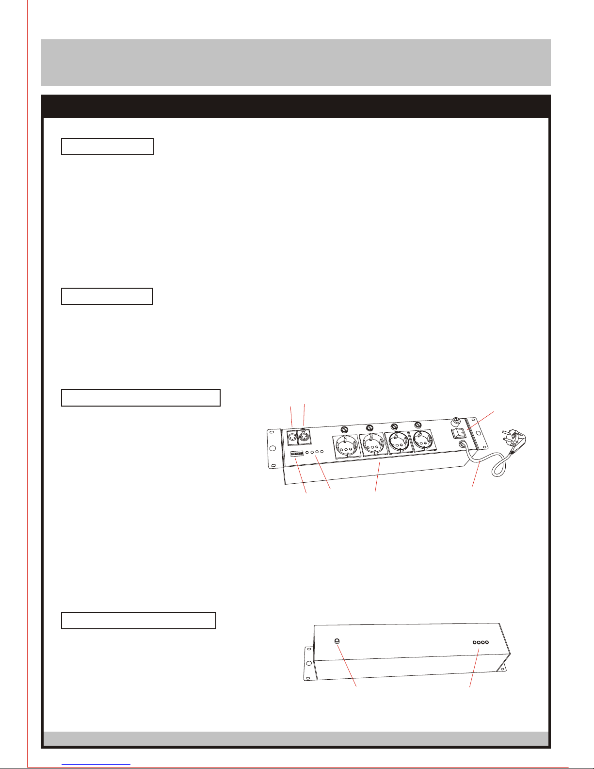
GENERAL FUNCTIONS ( FRONT )
1. Power Switch: The switch is used to
turn the unit ON / OFF.
2. Power Cord : It is used to supply main
power to the fixture.
3. DMX Input: It is used to receive incoming
DMX signal, such as DMX controller .
4. DMX Output: It is used to transmit the incoming DMX signal to another DMX fixture.
5. Dip Switches: These switches are used to assign a DMX address to the unit.
6. Power Output: It is used for the ON/OFF control for different equipment, such as lighting effects.
7. Channel LEDs: It will be on when the channel is working.
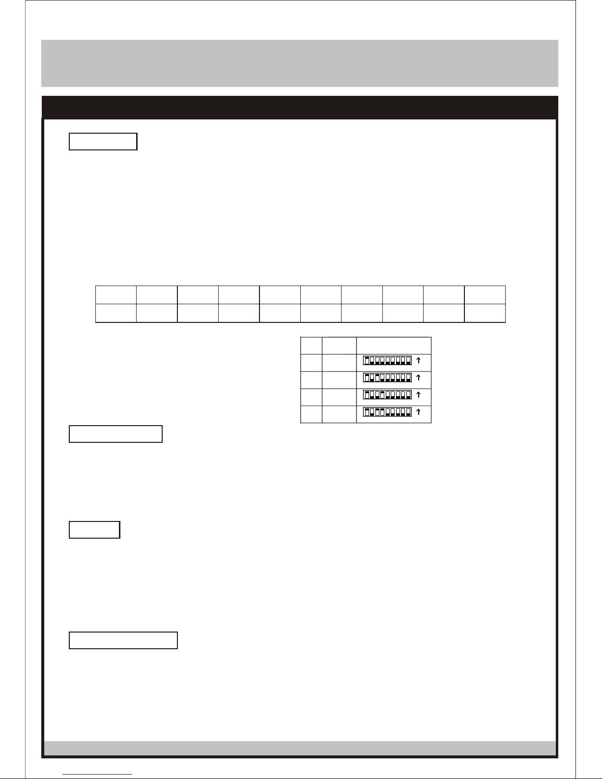
GENERAL FUNCTIONS ( REAR )
1-
1. Power LED: It will be lighted when the unit is ON.
2. Channel LEDs: It will be lighted when the channel
is working.
Page 2
DMX SWITCH PACK
SW-416
INSTALLATION
TROUBLESHOOTING
CAUTION
POWER CONNECTIONS
2-
The switch pack is equipped with 4 DMX channels, it can be controlled by universal DMX controller, and
each channel can be used for the ON/OFF
to control the switch pack, you have to set DMX so that the unit can receive DMX signal.
control for different equipment, such as lightings effects. It will be
"ON" when the DMX value is above 130, and "OFF" when the DMX value under 120, the
LED will show the state of each channel on the front and back panel. If you use a universal DMX controller
address
- Start the address
. Select the channels of DMX controller.
. Dip switches:
. Examples:
Channel 1: dip /on: #1 (=1)
Channel 5: dip /on: #1, #3 (1+4=5)
Channel 9: dip /on: #1, #4 (1+8=9)
Channel 13: dip /on: #1, #3, #4 (1+4+8=13)
Dip
#1 #2
#3
#4 #5 #6 #7 #8 #9
Value
1 2
4
8 16
32
64 128 256
13
9
5
1
Channel
4
3
1
2
Unit
ON
ON
ON
ON
Dip Switch Setting
3
321
1 2
54 76 8 9
54 6 87 9
3
31 2
1 2
54 6
54 6
87 9
87 9
- If the switch pack is not functional, check main power supply is "'ON" and check the fuse.
- I
- If after trying these solutions, you still have a problem, contact your dealer for technical assistance.
f the switch pack is functional but equipment ( light fixture ) does not light on- check if lamp works properly
or check if the DMX address is correct.
- Do not ater or other liquids into or onto your unit.
- Always disconnect the main power before
- Never open the unit while in use.
- No user serviceable parts inside, please refer to the nearest authorized technical assistance office
for service.
splash w
serving, repair or fuse replacement.
The unit is supplied with a power plug appropriate to its voltage and destination. Should any other
connections be required they must be carried out with the following configuration.
Earth = Green/Yellow cable
Neutral = Blue cable
Live = Brown cable
 Loading...