

Page 1

Operation Manual
Mode d'emploi
Gebruiksaanwijzing
Bedienungsanleitung
Manual de instrucciones
Manual do utilizador
Version: 1.0
The Power Source for DJ’s
MULTIBAND SOUND PROCESSOR
Page 2

ENGLISH OPERATION MANUAL
JB SYSTEMS 1/23 SE 100
OPERATION MANUAL
FEATURES
y Professional multi-band sound enhancer: adds harmonics to the sound which
increases definition, presence and transparency.
y Improves bass punch considerably
y Separate variable subwoofer output with adjustable cutoff frequency
y Subwoofer inverter switch
y 50Hz/100Hz low cut filter
y Variable sound processing for perfect sound balance
y Enhancer multi-band tuning from 1kHz to 8kHz.
y Balanced XLR inputs/outputs
BEFORE USE
Check the contents:
Check that the carton contains the following items:
1. SE 100 Enhancer unit
2. Operating instructions
3. Power cord with IEC-plug
Some important instructions:
• Read and then keep all safety and operating instructions for future reference.
• For your safety, follow all cautions and warnings in the user manual and on the
product.
• Do not use the product near excessive heat sources; these include radiators, heat
registers, flood lamps, spotlights, stoves, and other appliances.
• Properly vent the product if you mount it in a rack with other electronic equipment.
Vent the rear of the rack to prevent excessive heat build-up.
• Avoid places that are dusty and humid.
• To prevent fire or shock hazard, do not expose this appliance to rain or moisture.
• In order to prevent electric shock, do not open the top cover. If a problem occurs,
contact your dealer.
• Do not place metal objects or spill liquid inside the unit. Electric shock or
malfunction may result.
• Always route cables to keep them from being pinched or cut by heavy or sharp
objects.
Page 3
ENGLISH OPERATION MANUAL
JB SYSTEMS 2/23 SE 100
CONNECTIONS
This sound enhancer can be used in different ways. Basically the unit is connected
between the music source (any line output is possible) and the unit that will be used
to record or amplify the music:
• In most cases SE100 will be used to enhance the sound quality and bass
punch in PA systems and discotheque sound systems. The SE100 will be
connected behind the master output of the audio mixer. You can also use the
subwoofer output to drive an extra subwoofer amplifier which results in an
additional power punch!
• SE100 can be inserted in the monitor send of a PA mixer to enhance the
sound quality of monitor speakers.
• SE100 can also be used between a tape deck and mixing console to enhance
the sound of the tape deck.
• SE100 can be connected between the record output of a mixing console and a
tape deck to enhance the sound that will be recorded.
• SE100 can be used to correct the loss of sound quality, caused by all kinds of
effect equipment. In this case put the SE100 as last unit in the chain of effect
equipment.
• SE100 can be used to compensate the loss of sound definition during tape
duplication: the copy can be even better than the original! Put the SE100
between the output of the playback deck and the input of the recording deck.
For additional information on connections please refer to the next paragraph.
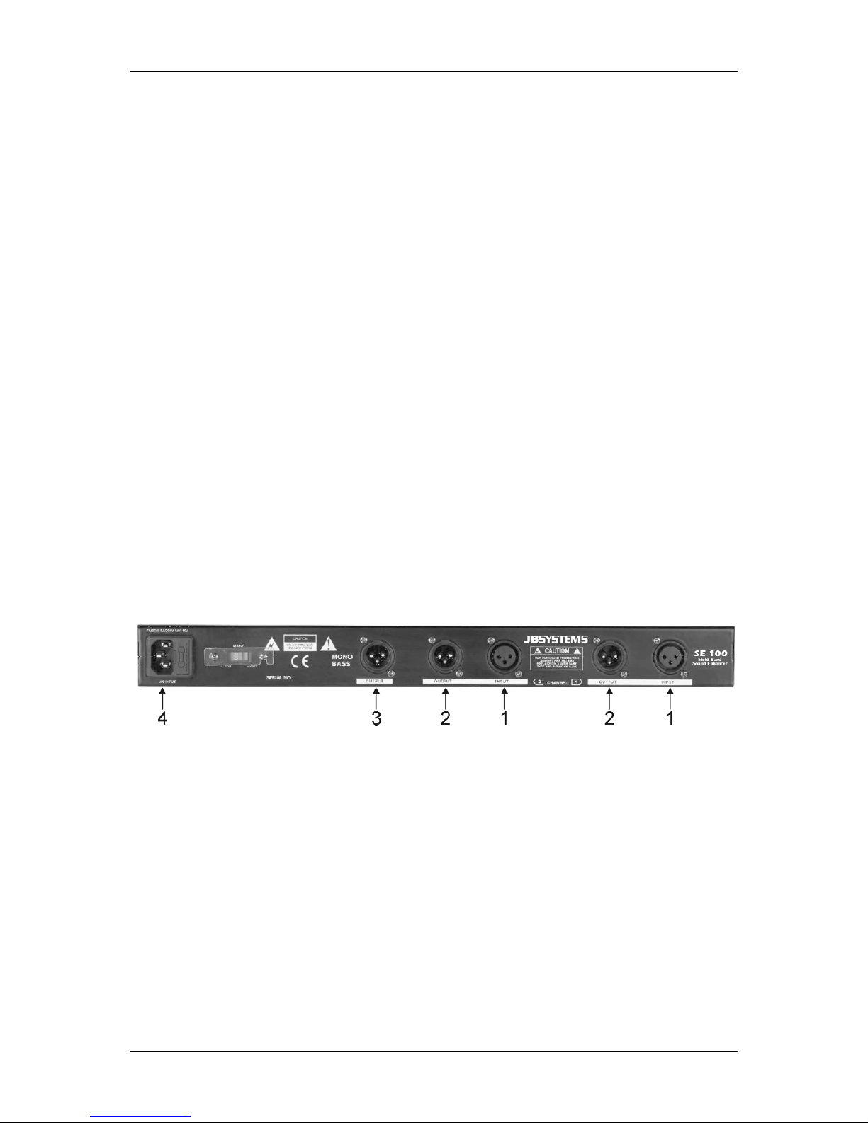
REAR PANEL:
CONNECTIONS
1. INPUT connector: this female XLR-connector accepts both unbalanced and
balanced line signals from the unit that needs audio enhancement.
• For balanced use, please follow these conventions:
Pin1 = Ground ~ Pin2 = Hot (+) ~ Pin3 = Cold (-)
Readymade cables are available from JB Systems (ex. 7-0063 ~ 5m XLR m/f)
• For unbalanced use, connect Pin3 (-) to Pin1 (ground/shield)
Readymade cables are available from JB Systems (2-0445 ~ cinch/XLR m)
2. OUTPUT connector: this male XLR-connector can be connected to both
unbalanced and balanced line inputs.
• For balanced use, please follow these conventions:
Pin1 = Ground ~ Pin2 = Hot (+) ~ Pin3 = Cold (-)
Readymade cables are available from JB Systems (ex. 7-0063 ~ 5m XLR m/f)
• For unbalanced use, connect Pin3 (-) to Pin1 (ground/shield)
Readymade cables are available from JB Systems (2-0440 ~ cinch/XLR f)
Page 4
ENGLISH OPERATION MANUAL
JB SYSTEMS 3/23 SE 100
3. SUBWOOFER OUTPUT connector: this male XLR-connector can be connected
to both unbalanced and balanced inputs of subwoofer amplifiers. The cutoff
frequency and level of this output are adjustable.
• For balanced use, please follow these conventions:
Pin1 = Ground ~ Pin2 = Hot (+) ~ Pin3 = Cold (-)
Readymade cables are available from JB Systems (ex. 7-0063 ~ 5m XLR m/f)
• For unbalanced use, connect Pin3 (-) to Pin1 (ground/shield)
Readymade cables are available from JB Systems (2-0440 ~ cinch/XLR f)
4. Mains input: connect the sound enhancer to the 220V AC mains, using the
supplied power-cord.
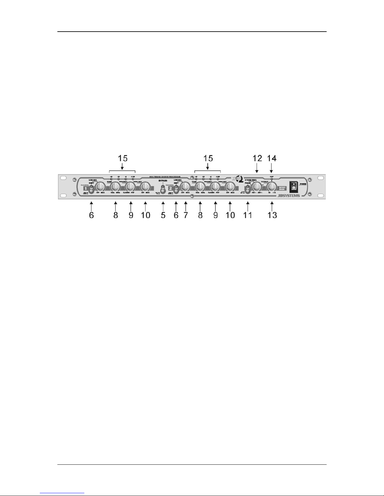
FRONT PANEL: CONTROLS AND USE
5. BYPASS switch: This button switches the processor over between operation
and bypass. When the button is pressed the blue led turns on to indicate that the
processor works. You can use this switch to compare the sound with and without
processing. This makes it easier to tune the sound using trial and error.
6. SHIFT switch: Sets the cutoff lower frequency of the bass processor. Depending
on the situation you can select 50Hz or 100Hz cutoff frequency for the bass
processor. This function also helps reducing system load.
7. LOW MIX control: Controls the amount of low band signal, produced by the bass
processor, used for sound enhancement (from zero to maximum). The setting
depends on the application and can be adapted to your own taste. When
adjusting, use the BYPASS switch to compare between original and processed
sound.
Important: Note that the bass processor should be used with care to avoid
possible speaker damage. Most smaller and economical speakers are not
capable of handling the low frequencies produced by this unit.
8. TUNE control: Sets the cutoff frequency of the high-pass filter. In a range from
1kHz to 8kHz you can select the frequencies that are routed to the high band
processor.
9. PROCESSOR control: controls the efficiency of the high band processor. The
signals’ transparency and sharpness increases while turning the control knob in
clockwise direction. When adjusting, use the BYPASS switch to compare
between original and processed sound.
10. HIGH MIX control: Controls the amount of signal, produced by the high band
processor, used for sound enhancement (from zero to maximum). The setting
depends on the application. It can be used to give a high-quality system the little
“finishing touch” it needs or you can add some extra clarity to a relatively poor
sound system. In any case it is up to you to adapt the sound to your own taste.
Always start adjusting with the HIGH MIX control turned in counterclockwise
Page 5

ENGLISH OPERATION MANUAL
JB SYSTEMS 4/23 SE 100
position and use the BYPASS switch often to compare between original and
processed sound.
Important: Note that the high band processor should be used with care to avoid
possible tweeter damage. Improper and excessive use of high band processor
can cause overload to the tweeters of your speakers. Always start tuning the high
band processor with the HIGH MIX control completely turned to the left.
11. PHASE INVERT switch: To add more bass punch, a subwoofer can be
connected to the subwoofer output. Sometimes the conductors of the subwoofer
are inversed which results in poor sound quality with a lack of low frequencies:
the opposite of what you expected! This can be corrected by inversing the (+) and
(-) poles of the cabling to your subwoofer or … by pushing the PHASE INVERT
switch! Press the phase invert switch and compare the results of both positions.
The position with the most bass production is the right one!
12. X-OVER FREQ. control: (crossover frequency control) adjusts the cutoff
frequency of the subwoofer low pass filter. This crossover frequency can be set in
a range of 100 to 250Hz. Once again it is up to you to adapt its position to your
own taste. For most subwoofers 100Hz to 150Hz seems to be the best choice.
13. OUTPUT control: Controls the level of the subwoofer output from zero to +12dB.
Start from zero and slowly turn in clockwise direction until the amount of low
frequencies seems to be OK for you.
14. CLIP LED: When the subwoofer output level is too big, clipping may occur. In this
case the clip led turns on. No problem if the led blinks from time to time. However
when this happens too often, it’s time to lower the subwoofer output signal.
Note: Clipping means deformation and deformation means possible damage to
your subwoofer…
15. LED BAR: Small led bar indicates the output level of both enhancer outputs.
SPECIFICATIONS
Max. input level / impedance: +20dBu unbalanced / 40kΩ
Max. output level / impedance: +20dBu unbalanced / 40Ω
Common mode rejection (CMRR): >40dB
Frequency response: 10-30.000Hz (+/-0.5dB)
THD(A) + noise: 0.005% +4dB
IMD Intermodulation distortion: 0.01% +10dB
S/N Ratio (IHF-A): >94dB (20-20.000Hz)
Crosstalk @20kHz: > -83dBu
Power Supply: AC 230 V, 50Hz
Power Consumption: 10W
Fuse: 0.5A slow blow
Dimensions: 482(W) x 44(H) x 154(D) mm
Weight: 1Kgs
SURF TO:
WWW.BEGLEC.COM
AND LOOK FOR OTHER PRODUCTS FROM JB SYSTEMS
Page 6

FRANCAIS MODE D’EMPLOI
JB SYSTEMS 5/23 SE 100
MODE D’EMPLOI
CARACTERISTIQUES
y Sound enhancer multi-bandes professionnel: ajoute des harmoniques au son, ce
qui augmente la définition, la présence et la transparence.
y Accentue considérablement les basses (plus de punch)
y Sortie séparée pour le sub-woofer avec réglage du niveau de sortie et de la
fréquence de coupure.
y Inverseur de polarité du sub-woofer
y Filtre « low cut » 50Hz/100Hz
y Traitement variable du son pour une balance sonore parfaite
y Enhancer multi-bandes : tuning de 1kHz à 8kHz.
y Entrées / sorties XLR balancées
AVANT L’UTILISATION
Vérifiez le contenu:
Vérifiez si la boite contient les articles suivants :
4. Le SE 100
5. Le mode d’emploi
6. Câble d’alimentation au connecteur IEC
Quelques instructions importantes:
• Lisez le mode d’emploi et conservez-le.
• Pour votre sécurité, consultez et appliquez toutes les remarques et mises en garde
qui se trouvent dans le mode d’emploi et sur l’appareil.
• N’utilisez jamais l’appareil près de sources de chaleur, par exemple : des radiateurs
de chauffage, lampes, projecteurs etc.
• Prenez garde à bien ventiler l’appareil si vous le montez en rack avec d’autres
appareils électroniques. Ventilez l’arrière du rack pour éviter une accumulation de
chaleur excessive.
• Evitez les endroits poussiéreux ou humides.
• Pour éviter l’incendie ou l’électrocution, n’exposez jamais cet appareil à la pluie ou
à l’humidité.
• Afin de ne pas vous faire électrocuter, n’enlevez jamais le couvercle. Si vous êtes
confrontés à un problème, contactez votre dealer.
• N’insérez jamais d’objets métalliques et ne renversez jamais de liquides dans
l’appareil. L’électrocution ou le mal fonctionnement de l’appareil peut en résulter.
• Prenez soin des câbles afin d’éviter qu’ils soient pincés ou coupés par des objets
lourds ou coupants.
Page 7

FRANCAIS MODE D’EMPLOI
JB SYSTEMS 6/23 SE 100
CONNECTIONS
Ce Sound Enhancer peut être utilisé de différentes façons. L’appareil sera connecté
entre la source sonore (n’importe quelle sortie ligne est possible) et l’appareil qui
sera utilisé pour enregistrer ou amplifier la musique:
• Dans la plupart des cas le SE100 sera utilisé pour améliorer la qualité sonore
et pour ajouter de punch aux basses fréquences dans des systèmes PA et les
systèmes sonores dans les discothèques. Le SE100 sera connecté à la sortie
Master de la table de mixage. Vous pouvez aussi utiliser la sortie sub-woofer
pour commander un amplificateur de sub-woofer supplémentaire, ce qui
donnera un résultat encore plus impressionnant !
• Le SE100 peut être inséré dans les sorties Monitor d’une console de mixage
pour PA pour augmenter la qualité sonore des retours.
• Le SE100 peut aussi être connecté entre la sortie d’un lecteur de cassettes et
une table de mixage pour augmenter la qualité sonore à l’écoute des
cassettes.
• Le SE100 peut être connecté entre la sortie d’enregistrement d’une table de
mixage et l’entrée d’un enregistreur afin d’augmenter la qualité de
l’enregistrement.
• Le SE100 peut être utilisé afin de corriger la perte de qualité sonore, causé
par toutes sortes d’effets. Dans ce cas, placez le SE100 comme dernier
maillon dans la chaîne d’effets.
• Le SE100 peut être utilisé pour compenser la perte de définition lors de la
duplication de bandes sonores. La copie peut même s’avérer meilleure que
l’original! Connectez le SE100 entre la sortie du deck de lecture et l’entrée du
deck d’enregistrement.
Pour plus d’informations sur les connections, referez vous au paragraphe suivant.
Page 8
FRANCAIS MODE D’EMPLOI
JB SYSTEMS 7/23 SE 100
PANNEAU ARRIÈRE: CONNECTIONS
1. INPUT: Ce connecteur d’entré XLR accepte des signaux ligne, balancés ou non,
des appareils qui ont besoin d’une amélioration sonore.
• Utilisez la configuration suivante pour une utilisation balancée:
Pinne1 = masse ~ Pinne2 = point chaud (+) ~ Pinne3 =point froid (-)
Des câbles tout-faits JB Systems sont disponibles (ex. 7-0063 ~ 5m XLR m/f)
• Pour une utilisation non-balancée, connectez la pinne3 (-) à la pinne1
Des câbles tout-faits JB Systems sont disponibles (2-0445 ~ cinch/XLR m)
2. OUTPUT: ce connecteur de sortie XLR peut être connecté aux entrées line
balancées ou non-balancées.
• Utilisez la configuration suivante pour une utilisation balancée:
Pinne1 = masse ~ Pinne2 = point chaud (+) ~ Pinne3 = point froid (-)
Des câbles tout-faits JB Systems sont disponibles (ex. 7-0063 ~ 5m XLR m/f)
• Pour une utilisation non-balancée, connectez la pinne3 (-) à la pinne1
Des câbles tout-faits JB Systems sont disponibles (2-0440 ~ cinch/XLR f)
3. SUBWOOFER OUTPUT: ce connecteur XLR mâle peut être connecté aux
entrées balancées ou non-balancées des amplificateurs de sub-woofer. La
fréquence de coupure et le niveau de sortie peuvent être ajustés.
• Utilisez la configuration suivante pour une utilisation balancée:
Pinne1 = masse ~ Pinne2 = point chaud (+) ~ Pinne3 = point froid (-)
Des câbles tout-faits JB Systems sont disponibles (ex. 7-0063 ~ 5m XLR m/f)
• Pour une utilisation non-balancée, connectez la pinne3 (-) à la pinne1
Des câbles tout-faits JB Systems sont disponibles (2-0440 ~ cinch/XLR f)
4. Mains input: connectez le Sound Enhancer au secteur 220V AC en utilisant le
câble d’alimentation fourni avec l’appareil.
Page 9

FRANCAIS MODE D’EMPLOI
JB SYSTEMS 8/23 SE 100
PANNEAU FRONTAL: + UTILISATION
5. Interrupteur BYPASS: vous permet de rendre le processeur opérationnel ou de
le mettre en bypass. Si la touche est enfoncée, le led bleu est allumé et indique
que le processeur est opérationnel. Vous pouvez utiliser cette touche pour
comparer le son original avec le son corrigé.
6. Interrupteur SHIFT: vous permet de sélectionner la fréquence de coupure du
processeur de basses. Selon les besoins, vous pouvez sélectionner 50Hz ou
100Hz. Cette fonction vous aide aussi à réduire la charge du système.
7. LOW MIX: Contrôle le niveau du signal produit par le processeur de basses
fréquences, utilisés pour l’augmentation de la qualité sonore (de zéro au
maximum) Le réglage dépend de l’application et peut être adapté selon votre
propre goût. Utilisez la touche BYPASS pendant le réglage, pour comparer le son
modifié au son original.
Important: Notez que le processeur de basses fréquences doit être utilisé avec
prudence pour éviter d’endommager les haut-parleurs. La plupart des hautparleurs bon- marchés ne sont pas capables de reproduire convenablement les
basses fréquences produits par cet appareil.
8. TUNE: Règle la fréquence de coupure du filtre des hautes fréquences. Vous
pouvez sélectionner les fréquences qui sont envoyés dans le processeur de
hautes fréquences, allant de 1kHz à 8kHz.
9. PROCESSOR: contrôle l’efficacité du processeur de hautes fréquences. La
transparence et la précision du signal augmentent si vous tournez le bouton dans
le sens des aiguilles d’une montre. Utilisez la touche BYPASS pendant le réglage
pour comparer le son modifié au son original
10. HIGH MIX: Contrôle le niveau du signal produit par le processeur de hautes
fréquences pour l’augmentation de la qualité sonore (de zéro au maximum) Le
réglage dépend de l’application. Il peut être utilisé pour ajouter cette petite
« touche finale » aux systèmes de haute qualité ou peut donner un peu plus de
clarté aux systèmes de moindre qualité. De toute façon, c’est à vous d’adapter le
son a votre propre goût. Commencez toujours avec le bouton de contrôle HIGH
MIX tourné en position de départ (contre-sens des aiguilles d’une montre) et
utilisez souvent la touche BYPASS pour comparer le son original au son corrigé
par le processeur.
Important: Notez que le processeur de hautes fréquences doit être utilisé avec
prudence pour éviter que le tweeter soit endommagé. Une utilisation excessive
inadaptée du processeur de hautes fréquences peut causer une surcharge des
tweeters de vos enceintes. Commencez toujours le réglage du processeur de
hautes fréquences avec le bouton de contrôle HIGH MIX complètement tourné
vers la gauche.
11. PHASE INVERT: Pour obtenir un meilleur rendu des basses fréquences on peut
connecter un sub-woofer à la sortie « sub-woofer » du processeur. Il se peut que
Page 10

FRANCAIS MODE D’EMPLOI
JB SYSTEMS 9/23 SE 100
les câbles du sub-woofer soient inversés, ce qui résulte en une mauvaise qualité
sonore, dépourvu de basses fréquences ; l’inverse de ce que l’on voulait obtenir !
Ceci peut être corrigé en inversant les pôles (+) et (-) du câblage du sub-woofer
ou... en appuyant simplement sur la touche PHASE INVERT ! (Inversion de
phase) Utilisez cette touche pour comparer le résultat dans chaque position. La
position qui produit le plus de basses est la bonne!
12. X-OVER FREQ: (contrôle de fréquence du cross-over) règle la coupure de
fréquence du filtre low-pass du sub-woofer. Cette fréquence peut être réglée de
100 à 250Hz. Une fois de plus, c’est à vous d’adapter ce réglage selon votre
propre goût. Pour la plupart de sub-woofers 100Hz à 150Hz semble être le
meilleur choix.
13. OUTPUT: Contrôle le niveau de sortie du sub-woofer de zéro à +12dB. Démarrez
de zéro et augmentez lentement le volume en tournant le bouton dans le sens
des aiguilles d’une montre, jusqu’a-ce que le niveau de basses fréquences désiré
soit obtenu.
14. CLIP LED: Quant le niveau de sortie du sub-woofer est trop élevé, une
déformation du son peut apparaître. Dans ce cas le Clip Led s’allume. Ceci ne
devrait pas poser de problèmes si le led s’allume de temps en temps pendant
une fraction de secondes. Par contre, si cela arrive trop souvent, il est grand
temps de diminuer le niveau de sortie du sub-woofer.
Remarque: Clipping signifie déformation et déformation signifie qu’il y à un risque
de dégât au haut -parleurs…
15. LED BAR: Le led-bar indique le niveau de sortie des deux sorties de l’appareil.
SPECIFICATIONS
Niveau Max d’entrée / impédance: +20dBu non-balancé / 40kΩ
Niveau Max de sortie / impédance: +20dBu non-balancé / 40Ω
Common mode rejection (CMRR): >40dB
Réponse de fréquence: 10-30.000Hz (+/-0.5dB)
THD(A) + bruit: 0.005% +4dB
IMD Intermodulation distortion: 0.01% +10dB
Rapport Signal/Bruit (IHF-A): >94dB (20-20.000Hz)
Séparation des canaux @20kHz: > -83dBu
Alimentation: AC 230 V, 50Hz
Consommation: 10W
Fusible: 0.5A lent
Dimensions: 482(L) x 44(H) x 154(P) mm
Poids: 1Kg
SURF TO:
WWW.BEGLEC.COM
AND LOOK FOR OTHER PRODUCTS FROM JB SYSTEMS
Page 11

NEDERLANDS GEBRUIKSAANWIJZING
JB SYSTEMS 10/23 SE 100
GEBRUIKSAANWIJZING
EIGENSCHAPPEN
y Professionele multi-band sound enhancer: voegt harmonischen tonen toe aan
de muziek wat de definitie en de transparantie verhoogt.
y Dynamiseert behoorlijk de bassen.
y Gescheiden regelbare subwoofer uitgang met instelbare afsnijfrequenties
y Polariteit inversieschakelaar voor de subwoofer
y 50Hz/100Hz low cut filter
y Variabele sound processor voor een perfecte geluidsbalans
y Enhancer multi-band tuning van 1kHz tot 8kHz.
y gebalanceerde XLR ingangen/uitgangen
VÓÓR GEBRUIK
Controleer de inhoud:
Kijk na of de doos volgende items bevat:
7. SE 100 Enhancer
8. Gebruiksaanwijzing
9. Voedingskabel met IEC stekker
Veiligheidsvoorschriften:
• Lees aandachtig de handleiding en de veiligheidsvoorschriften en houd deze bij
zodat ze later nog kunnen geraadpleegd worden.
• Voor uw veiligheid: volg nauwkeurig alle veiligheidsvoorschriften en opmerkingen
die in de handleiding en op het toestel staan.
• Gebruik dit toestel nooit in de nabijheid van warmtebronnen zoals radiatoren, spots,
kachels, enz.
• Zorg dat het toestel voldoende geventileerd wordt als U het met andere
elektronische apparatuur in een rack inbouwt. Ventileer in dit geval de achterkant
om een overdreven warmteaccumulatie te voorkomen.
• Vermijd stoffige en vochtige plaatsen.
• Stel dit toestel nooit bloot aan regen of zeer vochtige plaatsen, dit om brand en
elektrocutie te voorkomen.
• Om elektrocutie te voorkomen mag U nooit het toestel zelf openmaken. Contacteer
uw dealer als er zich een probleem voordoet.
Page 12

NEDERLANDS GEBRUIKSAANWIJZING
JB SYSTEMS 11/23 SE 100
• Plaats nooit metalen voorwerpen en mors geen vloeistoffen in het toestel.
Elektrocutie of een slechte werking kunnen hiervan het gevolg zijn.
• Let op bij het plaatsen van de kabels om te vermijden dat ze beschadigd worden
door zware of scherpe voorwerpen.
VERBINDINGEN
Deze sound enhancer kan op verschillende manieren gebruikt worden.
Normalerwijze wordt het toestel verbonden tussen de geluidsbron (elke line uitgang
is mogelijk) en het toestel dat gebruikt wordt om de muziek te versterken of op te
nemen:
• Meestal wordt de SE100 gebruikt om de geluidskwaliteit en de basweergave
van PA of discotheekinstallaties op te krikken. De SE100 wordt verbonden
aan de master uitgang van de mengtafel. Men kan ook de subwoofer uitgang
gebruiken om een extra subwoofer versterker aan te sturen, wat zal leiden tot
een nog krachtigere “Bass punch”!
• De SE100 kan in een monitor uitgang van een PA gevoegd worden om de
geluidskwaliteit van de monitors te verbeteren.
• De SE100 kan ook gebruikt worden tussen een tapedeck en een mengtafel
om de geluidskwaliteit van de tapedeck te verbeteren.
• De SE100 kan aangesloten worden tussen de opname-uitgang van een
mengtafel en een taperecorder om de geluidskwaliteit van de opname te
verbeteren.
• De SE100 kan gebruikt worden om het kwaliteitsverlies, veroorzaakt door het
gebruik van verschillende effectapparatuur, op te vangen. Plaats in dit geval
de SE100 als laatste schakel in de effectenketting.
• De SE100 kan gebruikt worden om het kwaliteitsverlies tijdens het dupliceren
van geluidsbanden te compenseren. De kopie kan zelfs beter klinken dan de
originele band! Plaats de SE100 tussen de uitgang van de tapedeck
(weergave) en de ingang van de taperecorder.
Zie volgende paragraaf voor bijkomende informatie over aansluitingen.
Page 13

NEDERLANDS GEBRUIKSAANWIJZING
JB SYSTEMS 12/23 SE 100
ACHTERZIJDE: aansluitingen
1. INPUT: deze vrouwelijke XLR aansluitingen aanvaarden zowel gebalanceerde als
niet-gebalanceerde line signalen van geluidsbronnen die een geluidsverbetering
nodig hebben.
• Volg volgende voorschriften voor een gebalanceerde aansluiting:
Pin1 = Grond ~ Pin2 = Warm (+) ~ Pin3 = Koud (-)
Afgewerkte JB Systems kabels zijn beschikbaar (bvb. 7-0063 ~ 5m XLR m/v)
• Voor een niet-gebalanceerde aansluiting: verbind Pin3 (-) met Pin1 (grond)
Afgewerkte JB Systems kabels zijn beschikbaar(2-0445 ~ cinch/XLR m)
2. OUTPUT: deze mannelijke XLR aansluitingen kunnen verbonden worden met
zowel gebalanceerde als niet-gebalanceerde line ingangen.
• Volg volgende voorschriften voor een gebalanceerde aansluiting:
• Pin1 = Grond ~ Pin2 = Warm (+) ~ Pin3 = Koud (-)
Afgewerkte JB Systems kabels zijn beschikbaar (7-0063 ~ 5m XLR m/v)
• Voor een niet-gebalanceerde aansluiting: verbind Pin3 (-) met Pin1 (grond)
Afgewerkte JB Systems kabels zijn beschikbaar (2-0440 ~ cinch/XLR v)
3. SUBWOOFER OUTPUT: deze mannelijke XLR aansluiting kan verbonden
worden met zowel gebalanceerde als niet-gebalanceerde ingangen van
subwoofer versterkers. De afsnijfrequentie en het volume van deze uitgang zijn
regelbaar.
• Volg volgende voorschriften voor een gebalanceerde aansluiting:
• Pin1 = Grond ~ Pin2 = Warm (+) ~ Pin3 = Koud (-)
Afgewerkte JB Systems kabels zijn beschikbaar (7-0063 ~ 5m XLR m/v)
• Voor een niet-gebalanceerde aansluiting: verbind Pin3 (-) met Pin1 (grond)
Afgewerkte JB Systems kabels zijn beschikbaar (2-0440 ~ cinch/XLR v)
4. MAINS input: verbindt de sound enhancer met het 220V AC net door middel van
de bijgeleverde voedingskabel.
Page 14

NEDERLANDS GEBRUIKSAANWIJZING
JB SYSTEMS 13/23 SE 100
FRONT: regelingen & gebruik
5. BYPASS switch: deze toets laat U toe de processor om te schakelen van
werking naar bypass, of omgekeerd. Wanneer deze toets ingedrukt is gaat de
blauwe led aan om aan te duiden dat de processor in werking is. U kan deze
toets gebruiken om het originele geluid met het bewerkte geluid te vergelijken. Dit
vergemakkelijkt het afstellen van de enhancer.
6. SHIFT switch: regelt de lage afsnijfrequentie van de basprocessor. Afhankelijk
van de omstandigheden kan men een afsnijfrequentie voor de basprocessor
kiezen van 50Hz of 100Hz. Deze functie helpt ook voor het verlagen van de
belasting van het systeem.
7. LOW MIX: regelt het volume van het lage frequentiesignaal, geproduceerd door
de basprocessor (van nul tot maximum) De afstelling hangt af van de toepassing
en kan aangepast worden naar uw eigen smaak. Gebruik de BYPASS switch
tijdens het afstellen om de originele klank met de verbeterde klank te vergelijken.
Belangrijk: de basprocessor moet in alle voorzichtigheid gebruikt worden om
schade aan de luidsprekers te voorkomen. De meeste kleine en goedkope
speakers zijn niet in staat om de lage frequenties die door deze processor
gegenereerd worden te bolwerken.
8. TUNE: Regelt de afsnijfrequentie van de high-pass filter. Kies de frequenties
tussen 1kHz en 8kHz die naar de high band processor moeten gestuurd worden.
9. PROCESSOR: regelt de doeltreffendheid van de high band processor. De
transparantie en de scherpte nemen toe als men de regelknop in wijzerzin
verdraait. Gebruik de BYPASS toets tijdens het afstellen om het originele geluid
met het bewerkte geluid te vergelijken.
10. HIGH MIX: regelt het volume van het signaal dat geproduceerd wordt door de
high band processor (van nul tot maximum). De afstelling hangt af van de
toepassing. Het kan gebruikt worden om aan kwaliteitsinstallaties een kleine
“finishing touch” toe voegen of om wat extra helderheid te creëren bij het gebruik
van minder goede geluidsinstallaties. Het is in elk geval aan U om het geluid aan
te passen naar uw eigen smaak. Begin steeds met de HIGH MIX controleknop
volledig in de tegenwijzerzin positie en gebruik regelmatig de BYPASS toets om
het originele geluid te vergelijken met het bewerkte geluid.
Belangrijk: De high band processor moet in alle voorzichtigheid gebruikt worden
om eventuele schade aan de tweeters te vermijden. Ongepast en overdreven
gebruik van de high band processor kan de tweeters oversturen. Start het
afstellen van de high band processor steeds met de HIGH MIX controleknop
volledig naar links gedraaid.
11. PHASE INVERT switch: Men kan een sub woofer aan de sub woofer uitgang
aansluiten om een dynamischer rendement van de bassen te bekomen. Soms
zijn de geleiders van de sub woofer omgekeerd met een slechte geluidskwaliteit
en een gebrek aan bassen tot gevolg. Dit is net het tegenovergestelde van wat
Page 15

NEDERLANDS GEBRUIKSAANWIJZING
JB SYSTEMS 14/23 SE 100
men wil bekomen! Dit kan echter gecorrigeerd worden door de (+) en (-) polen
van de bekabeling om te keren of... door op de PHASE INVERT toets te drukken!
Druk op de phase invert toets (omkeren van de fase) en vergelijk het resultaat in
beide posities. De positie met de meeste basweergave is de juiste!
12. X-OVER FREQ. control: (controle van de cross-over frequentie) Regelt de
afsnijfrequentie van de low pass filter van de sub woofer. Deze cross-over
frequentie kan ingesteld worden tussen 100 en 250Hz. Het is eens te meer aan U
om de instelling uit te voeren naargelang uw eigen smaak. Voor de meeste sub
woofers ligt de beste keuze tussen 100Hz en 150Hz.
13. OUTPUT: Regelt het uitgangsniveau van de sub woofer van nul tot +12dB. Start
vanaf nul en draai langzaam in wijzerzin tot de gewenste hoeveelheid lage tonen
bereikt is.
14. CLIP LED: wanneer het uitgangsniveau van de sub woofer te hoog is ingesteld
kan het toestel beginnen clippen. In dit geval gaat de clip led branden. Dit is niet
echt rampzalig als de led maar af en toe heel even pinkt. Wanneer dit echter te
veel voorkomt is het hoog tijd om het uitgangssignaal van de sub woofer te
verminderen.
Opgelet: Clippen betekent vervorming en vervorming kan schade toebrengen aan
uw sub woofer...
15. LED BAR: De kleine led bar duid het uitgangsniveau aan van beide enhancer
uitgangen.
TECHNISCHE GEGEVENS
Max. input level / impedance: +20dBu niet gebalanceerd / 40kΩ
Max. output level / impedance: +20dBu niet gebalanceerd / 40Ω
Common mode rejection (CMRR): >40dB
Frequency response: 10-30.000Hz (+/-0.5dB)
THD(A) + noise: 0.005% +4dB
IMD Intermodulation distortion: 0.01% +10dB
S/N Ratio (IHF-A): >94dB (20-20.000Hz)
Crosstalk @20kHz: > -83dBu
Voeding: AC 230 V, 50Hz
Verbruik: 10W
Zekering: 0.5A traag blow
Afmetingen: 482(W) x 44(H) x 154(D) mm
Gewicht: 1Kg
SURF TO:
WWW.BEGLEC.COM
AND LOOK FOR OTHER PRODUCTS FROM JB SYSTEMS
Page 16

DEUTSCH BEDIENUNGSANLEITUNG
JB SYSTEMS 15/23 SE 100
Bedienungsanleitung
EIGENSCHAFTEN
y Professioneller Multi-Band Sound Prozessor: optimiert den Sound, was zu
besserer Klarheit, Präsenz und Transparenz führt.
y Steigert den Bassdruck beachtlicht
y Separater variabler Subwoofer-Output mit regulierbarer Trennfrequenz
y Subwoofer Umkehrregler
y 50Hz/100Hz Low-cut-Filter
y Variable Soundverarbeitug für perfekte Klang-Balance
y Verstärker mit multi-band-Tuning von 1kHz bis 8kHz.
y Balanced XLR Inputs/Outputs
VOR DEM GEBRAUCH
Inhalt überprüfen:
Überprüfen Sie, ob der Karton folgende Teile beinhaltet:
10.SE 100 Prozessor Einheit
11.Bedienungsanleitung
12.Netzkabel
Wichtige Hinweise:
• Lesen Sie alle Sicherheits- und Bedienungshinweise und bewaren Sie diese zum
Nachschlagen auf.
• Beachten Sie zu Ihrer eigenen Sicherheit die Vorsichts- und Warnhinweise im
Benutzerhandbuch und auf dem Gerät.
• Verwenden Sie das Gerät nicht in der Nähe von starken Hitzequellen, wie z.B.
Heizkörper, Scheinwerfer, Öfen usw.
• Lassen Sie das Gerät abkühlen, bevor Sie es in ein Rack mit anderen
elektronischen Geräten montieren. Lassen Sie die Hinterseite des Racks geöffnet,
um starke Hitzebildung zu vermeiden.
• Vermeiden Sie staubige und feuchte Umgebungen.
• Um Feuer oder Elektroschlägen vorzubeugen, setzten Sie das Gerät nicht Regen
oder Feuchtigkeit aus.
• Um Stromschläge zu vermeiden, öffnen Sie das Gehäuse nicht eigenständig. Sollte
ein Problem auftauchen, wenden Sie sich an den Händler.
• Legen Sie keine magnetischen Metallgegenstände auf das Gerät und lassen Sie
keine Flüssigkeit ins Innere kommen, um Stromschläge und Funktionsstörungen zu
vermeiden.
• Legen Sie die Kabel immer so, dass sie nicht eingeklemmt sind und nicht durch
schwere oder scharfkantige Gegenstände beschädigt werden können.
Page 17

DEUTSCH BEDIENUNGSANLEITUNG
JB SYSTEMS 16/23 SE 100
ANSCHLUSSFELDER
Diesen Sound-Prozessor kann man auf verschiedene Weise benutzen.
Grundsätzlich wird das Gerät zwischen der Musikquelle (jeder Line-Output ist
möglich) und der Einheit, die für Aufnahmen oder Musikverstärkung eingesetzt wird,
angeschlossen. Meistens wird der SE100 verwendet, um die Soundqualität und den
Bass-Druck in PA- und Discotheken-Beschallungsanlagen zu verbessern. Der SE100
wird hinter dem Master-Output des Audio-Mixers angeschlossen. Sie können auch
den Subwoofer-Output verwenden, um einen Extra Subwoofer-Verstärker zu
betreiben, der zusätzlichen Power-Schub bewirkt!
• SE100 kann zwischen Mischpult und Monitor angeschlossen werden, um den
Monitor zu verstärken.
• SE100 kann auch zwischen Tape-Deck und Mixer-Konsole verwendet
werden, um den Sound des Tape-Decks zu verstärken.
• SE100 kann zwischen dem Record-Output einer Mixer-Konsole und einem
Tape-Deck verwendet werden, um den Sound, der aufgenommen wird, zu
verstärken.
• SE100 kann verwendet werden, um den Sound-Verlußt auszugleichen, der
durch viele Effektgeräte ausgelöst wird. Setzen Sie in diesem Fall den SE100
als letzte Einheit der Effekt-Anlage ein.
• SE100 kann verwendet werden, um den Soundqualitätsverlust während einer
Tapeüberspielung zu kompensieren: die Kopie kann sogar besser als das
Original sein! Platzieren Sie den SE100 zwischen den Ausgang des Playback-
Decks und den Eingang des Aufnahme-Decks.
Für zusätzliche Informationen über Anschlussfelder beachten Sie bitte den nächsten
Abschnitt.
Page 18

DEUTSCH BEDIENUNGSANLEITUNG
JB SYSTEMS 17/23 SE 100
RÜCKSEITE: ANSCHLUSSFELDER
1. INPUT Anschluss: Dieser Female XLR-Verbinder akzeptiert beide Line-Signale
(unsymmetrisch und symmetrisch) der Geräteeinheit, die Audio-Verstärkung
benötigt.
• Für den symmetrischen Gebrauch beachten Sie bitte die folgende Belegung:
Pin1 = Ground Pin2 = + Pin3 = Fertige Kabel sind verfügbar von JB Systems (z.B. 7-0063 ~ 5m XLR m/f)
• Für den unsymmetrischen Gebrauch schließen Sie Pin3 (-) an Pin1 (ground)
Fertige Kabel sind verfügbar von JB Systems (z.B. 2-0445 ~ cinch/XLR m)
2. OUTPUT Anschuss: Dieser Male XLR-Verbinder akzeptiert beide Line-Signale
(unsymmetrisch und symmetrisch).
• Für den symmetrischen Gebrauch beachten Sie bitte die folgende Belegung:
Pin1 = Ground Pin2 = + Pin3 = -
• Fertige Kabel sind verfügbar von JB Systems (z.B. 7-0063 ~ 5m XLR m/f)
• Für den unsymmetrischen Gebrauch schließen Sie Pin3 (-) an Pin1 (ground)
Fertige Kabel sind verfügbar von JB Systems (z.B. 2-0440 ~ cinch/XLR f)
3. SUBWOOFER OUTPUT Anschluss: Dieser Male XLR-Verbinder kann mit
beiden Inputs von Subwoofer-Verstärkern (unsymmetrisch und symmetrisch)
verbunden werden. Die Trenn-Frequenz und der Level dieses Outputs sind
verstellbar.
• Für den symmetrischen Gebrauch beachten Sie bitte die folgende Belegung:
Pin1 = Ground Pin2 = + Pin3 = -
• Fertige Kabel sind verfügbar von JB Systems (z.B. 7-0063 ~ 5m XLR m/f)
• Für den unsymmetrischen Gebrauch schließen Sie Pin3 (-) an Pin1 (ground)
Fertige Kabel sind verfügbar von JB Systems (z.B. 2-0440 ~ cinch/XLR f)
4. Mains Input: Verbinden Sie den Sound-Prozessor mit dem 230V-Stromnetz/AC
mit dem beiliegenden Netzkabel.
Page 19

DEUTSCH BEDIENUNGSANLEITUNG
JB SYSTEMS 18/23 SE 100
FRONTSEITE: EINSTELLUNG UND ANWENDUNG
5. BYPASS Schalter: Dieser Knopf steuert den Prozessor zwischen Betrieb und
Standby. Bei gedrücktem Knopf erleuchtet die blaue Lampe, um zu zeigen, dass
der Prozessor in Betrieb ist. Sie können diesen Schalter dazu verwenden, um
den Klang mit und ohne Prozessor zu vergleichen. Dies vereinfacht das tunen
des Klangs mit der Trial-und-Error-Funktion.
6. SHIFT Schalter: Legt die Trennung niedrigerer Frequenzen des Bass-
Prozessors fest. Je nach Situation können Sie eine Trenn-Frequenz für den
Bass-Prozessor von 50Hz oder 100Hz auswählen.
7. LOW MIX Regler: Kontrolliert das Low-Band-Signal, das vom Bass-Prozessor
erzeugt wird und das für die Soundverstärkung benutzt wird (von Null bis
Maximum). Die Einstellung hängt von der Anwendung ab und kann nach Ihren
eigenen Vorstellungen angepasst werden. Benutzen Sie beim Anpassen den
BYPASS-Schalter, um zwischen Originalklang und Klang mit Prozessor zu
vergleichen.
Wichtig: Beachten Sie, dass mit dem Bass-Prozessor vorsichtig umgegangen
werden muss, um mögliche Schäden beim Lautsprecher zu vermeiden. Die
meisten kleineren und günstigeren Lautsprecher sind nicht in der Lage, die
niedrigen Frequenzen, die von dieser Einheit erzeugt werden, umzusetzen.
8. TUNE Regler: Legt die Trenn-Frequenz der High-Pass-Filters fest. In einer
Spanne von 1kHz bis 8kHz können Sie die Frequenzen, die im High-BandProzessor liegen, auswählen.
9. PROZESSOR Regler: Kontrolliert die Effizienz des High-Band-Prozessors. Die
Transparenz und Schärfe des Signals steigen, wenn Sie den Knopf in
Uhrzeigerrichtung drehen. Benutzen Sie beim Anpassen den Bass-Regler, um
zwischen Originalklang und Klang mit Prozessor zu vergleichen.
10. HIGH MIX Regler: Kontrolliert das Signal, das vom High-Band-Prozessor
erzeugt wird und das für die Soundverstärkung benutzt wird (von Null bis
Maximum). Die Einstellung hängt von der Anwendung ab. Der Regler kann
benutzt werden, um einem Hochqualitäts-System den „letzten Touch“ zu geben
oder um einem schwächeren Sound-System mehr Klarheit und Power zu geben.
In jedem Fall bleibt es Ihnen überlassen, den Klang nach ihrem Geschmack
anzupassen. Fangen Sie beim Anpassen immer mit dem HIGH-MIX-Regler in
Ausgangsposition (gegen den Uhrzeigersinn bis zum Anschlag gedreht) an, und
benutzen Sie den BYPASS-Regler öfters, um zwischen Originalsound und dem
Sound mit Prozessor zu vergleichen.
Wichtig: Beachten Sie, dass mit dem High-Band-Prozessor vorsichtig
umgegangen werden muss, um möglichen Schäden beim Hochtöner zu
vermeiden. Der falsche und übermäßige Gebrauch der High-Band-Prozessors
kann zu einer Überlastung des Hochtöners Ihres Lautsprechers führen. Fangen
Page 20

DEUTSCH BEDIENUNGSANLEITUNG
JB SYSTEMS 19/23 SE 100
Sie beim regeln des High-Band-Prozessors immer an, wenn der HIGH MIX
Regler ganz nach links gedreht ist.
11. PHASE INVERT Regler: Um mehr Bass-Druck zu erhalten, kann ein Subwoofer
am Subwoofer-Ausgang angeschlossen werden. Manchmal sind die Leiter von
Subwoofern vertauscht, was zu niedriger Soundqualität mit fehlenden niedrigen
Frequenzen führt. Dies kann durch tauschen der (+) und (-) Pole der Kabel an
ihrem Subwoofer korrigiert werden, oder durch Drücken der PHASE INVERT
Taste! Drücken Sie die PHASE INVERT Taste und vergleichen Sie die
Ergebnisse beider Möglichkeiten. Die Möglichkeit, bei der am meisten Bass
erzeugt wird, ist die richtige!
12. X-OVER FREQUENZ Regler: (Crossover-Frequenz-Regler) Passt die Trenn-
Frequenz des Niedrig-Pass-Filters des Subwoofers an. Diese CrossoverFrequenz kann zwischen 100 und 250Hz liegen. Erneut bleibt es Ihnen
überlassen, die Position des Reglers nach ihrem Geschmack anzupassen. Für
die meisten Subwoofer stellt sich eine Frequenz von 100Hz bis 150Hz als beste
Wahl heraus.
13. OUTPUT Regler: Kontrolliert den Level des Sobwoofer-Outputs von Null bis
+12dB. Starten Sie bei Null und drehen Sie langsam im Uhrzeigersinn, bis der
Anteil an niedriger Frequenz für Sie angenehm ist.
14. CLIP LED: Falls der Output-Level des Subwoofers zu groß ist, kann eine
Übersteuerung auftreten. In diesem Fall geht das Clip-Licht an. Es ist nicht
schlimm, wenn das Licht von Zeit zu Zeit blinkt. Wenn dies jedoch zu häufig
vorkommt, sollten Sie das Output-Signal der Subwoofers niedriger stellen.
Beachten Sie: Übersteuerung kann zu einem möglichen Schaden an Ihrem
Subwoofer führen.
15. LED Anzeige: Die kleine LED-Anzeige zeigt den Output-Level beider Prozessor-
Ausgänge.
TECHNISCHE DATEN
Max. Input Level / Impedanz: +20dBu unsymmetrisch/ 40kΩ
Max. Output Level / Impedanz: +20dBu unsymmetrisch/ 40Ω
Common mode rejection (CMRR): >40dB
Frequenzgang: 10-30.000Hz (+/-0.5dB)
THD(A) + noise: 0.005% +4dB
IMD Intermodulation distortion: 0.01% +10dB
Rauschabstand (IHF-A): >94dB (20-20.000Hz)
Crosstalk @20kHz: > -83dBu
Stromversorgung: AC 230 V, 50Hz
Anschlusswert: 10W
Sicherung: 0.5A s
Maße: 482(B) x 44(H) x 154(T) mm
Gewicht: 1Kg
SURF TO:
WWW.BEGLEC.COM
AND LOOK FOR OTHER PRODUCTS FROM JB SYSTEMS
Page 21

ESPAÑOL MANUAL DE INSTRUCCIONES
JB SYSTEMS 20/23 SE 100
MANUAL DE INSTRUCCIONES
CARACTERISTICAS
y Procesador de sonido profesional multi-bandas: aumenta las armonicas del
sonido y su definición, presencia y transparencia
y Enriquece considerablemente el rendido de las frecuencias bajas
y Ajuste del corte de frecuencias para separar la salida ajustable del subwoofer
y Interruptor de inversión del subwoofer
y Filtro de corte de frecuencias bajas 50/100Hz
y Procesador de sonido ajustable para obtener un sonido perfecto
y Procesador multi-bandas de 1KHz a 8KHz
y Salidas y entradas XLR balanceadas
ANTES DEL USO
Comprobar la presencia de los siguientes componentes:
13.Unidad SE 100
14.Manual de instrucciones
15.Cable de alimentación IEC
Instrucciones importantes:
• Leer y recojer estas instrucciones para consultarlas mas adelante
• Para evitar todo riesgo, seguir las instrucciones de este manual y las indicaciones
sobre la unidad
• No colocar o utilizar la unidad mucho tiempo en sitios calientes (al lado de
amplificadores, radiadores, focos,…)
• Instalar la platina en un sitio con buena ventilación para no exponerla a altas
temperaturas .Ventilar la parte trasera
• Evitar sitios sucios y humedos
• Para evitar riesgos de electrocución o incendio, evitar la exposición a la lluvia o
humedad
• Para evitar riesgos de electrocución, no abrir la unidad. En caso de problema,
pongase en contacto con su vendedor.
• No insertar liquidos o objetos de metal en la unidad.
• Proteger los cables para evitar romperlos con objetos cortantes o pesados.
Page 22

ESPAÑOL MANUAL DE INSTRUCCIONES
JB SYSTEMS 21/23 SE 100
CONECCIONES
Este procesador de sonido tiene varias utilidades. De forma general, la unidad se
conecta entre una fuente de sonido (salidas 'linea') y la unidad de gravación o de
amplificación:
• La SE100 permite enriquecer la calidad del sonido y la potencia sonora de las
frecuencias bajas sobre equipos profesionales y discotecas. Conectar la
salida master de la mesa mezcladora al SE100. Tambien se puede conectar
la salida subwoofer a una etapa de potencia para subwoofer.
• La SE100 puede conectarse entre monitores y la salida de una mesa
profesional para una mejoria del sonido de los monitores.
• La SE100 puede conectarse entre un cassette y una mesa para mejorar la
calidad de reproducción del cassette.
• La SE100 pueded conectarse entre un gravador (cassette, MD,…) y la salida
de una mesa para mejorar la gravación.
• La SE100 permite corregir la perdida de calidad de cualquier equipo, en este
caso conectar como ultima unidad del equipo.
• La SE100 permite compensar la perdida de calidad durante la duplicación de
cassettes : la cinta copia puede resultar hasta mejor que la cinta original!
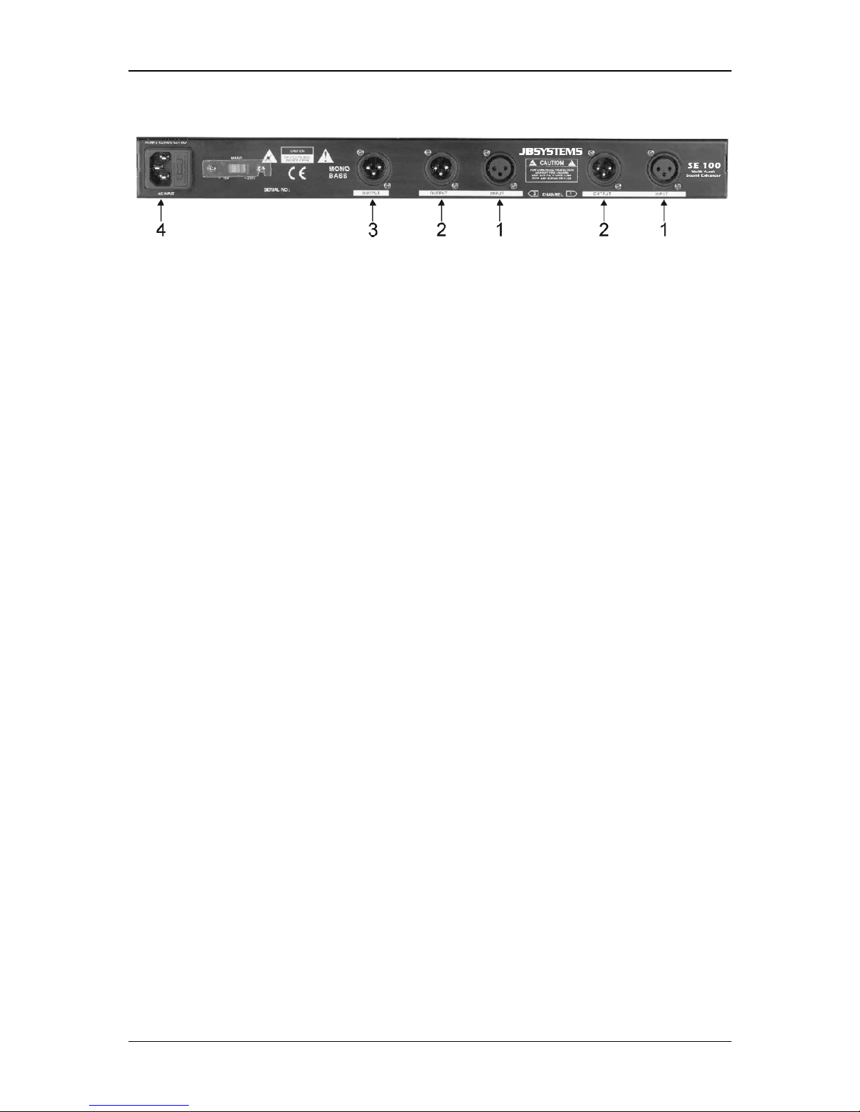
REAR PANEL:
CONNECTIONS
1. ENTRADA: este conectador de entrada XLR hembra accepta señales
balanceadas o sin balancear.
• Para uso balanceado:
Pin1 = Masa ~ Pin2 = Positivo (+) ~ Pin3 = Negativo (-)
Existen cables JB Systems listos para el uso (ex. 7-0063 ~ 5m XLR m/f)
• Para uso sin balancear:
Pin3 Negativo (-) Pin1 (Masa)
Existen cables JB Systems listos para el uso (2-0445 ~ cinch/XLR m)
2. SALIDA: este conectador de salida XLR macho puede conectarse a entradas
balanceadas o sin balancear.
• Para uso balanceado:
Pin1 = Masa ~ Pin2 = Positivo (+) ~ Pin3 = Negativo (-)
Existen cables JB Systems listos para el uso (ex. 7-0063 ~ 5m XLR m/f)
• Para uso sin balancear:
Pin3 Negativo (-) Pin1 (Masa)
Existen cables JB Systems listos para el uso (2-0445 ~ cinch/XLR m)
3. SALIDA SUBWOOFER: este conectador de salida XLR macho puede
conectarse a entradas de amplificadores para subwoofer balanceadas o sin
balancear. El corte de frecuencia y el nivel de esta salida pueden ser ajustados.
• Para uso balanceado:
Page 23

ESPAÑOL MANUAL DE INSTRUCCIONES
JB SYSTEMS 22/23 SE 100
Pin1 = Masa ~ Pin2 = Positivo (+) ~ Pin3 = Negativo (-)
Existen cables JB Systems listos para el uso (ex. 7-0063 ~ 5m XLR m/f)
• Para uso sin balancear:
Pin3 Negativo (-) Pin1 (Masa)
Existen cables JB Systems listos para el uso (2-0445 ~ cinch/XLR m)
4. Alimentación: conectar a una fuente 220V AC con el cable de alimentacíon.
PANEL FRONTAL: CONTROLES Y FUNCIONES
5. Interruptor BYPASS: este botón sirve de interruptor para el procesador. Al
pulsarlo, el testigo azúl se enciende y el procesador se pone en modo de
funcionamiento. Utilize este boton para comparar el sonido mejorado con el de
orígen. Esto facilita las operaciones.
6. Interruptor SHIFT: Permite seleccionar el corte de frecuencias bajas. Según la
situación, seleccionar una frecuencia de corte de 50 o 100Hz. Esta función
permite reducir la carga del equipo.
7. Controlador LOW MIX: Controla la cantidad de señal producida por el
procesador de bajas frecuencias, utilizado para amejorar el sonido (de zero al
maximo). El ajuste depende de la aplicación y del gusto de cada uno. Utilizar el
interruptor BYPASS para comparar con el sonido original.
Importante: Utilizar el procesador de frecuencias bajas con cuidado para evitar
causar daños a los altavozes. Cajas pequeñas y baratas no están previstas para
reproducir estos sonidos.
8. Controlador TUNE: Permite seleccionar el corte de frecuencias altas.
Seleccionar la frecuencia del filtro de frecuencias altas de 1kHz to 8kHz.
9. Controlador PROCESSOR: Controla la eficacidad del procesador de
frecuencias altas. Al girar el controlador hacia la derecha, la transparencia y la
precisión del sonido. Utilizar el interruptor BYPASS para comparar con el sonido
original.
10. Controlador HIGH MIX: Controla la cantidad de señal producida por el
procesador de frecuencias altas, utilizado paramejorar el sonido (de zero al
maximo). El ajuste depende de la aplicación. Puede utilizarse para dar un 'toque
de finición' a un equipo de alta calidad o para añadir claridad a un equipo de
menor calidad. En todo caso, el ajuste depende del gusto de cada uno. Siempre
empezar el ajuste con el controlador en posición izquierda y utilizar el BYPASS
para coparar con el sonido original.
Important: Utilizar el procesador de frecuencias altas con cuidado para evitar
causar daños a los altavozes. Uso excesivo del procesador de frecuencias altas
Page 24

ESPAÑOL MANUAL DE INSTRUCCIONES
JB SYSTEMS 23/23 SE 100
puede causar sobrecarga y resultar en daños para los altavozes.Siempre
empezar el reglaje con el controlador completamenta a la izquierda.
11. Interruptor PHASE INVERT: Al conectar un subwoofer, mucha gente inversa los
conductores. El resultado es un sonido de baja calidad con pocas frecuencias
bajas. Para corregir, inversar los conductores (+) y (-) del subwoofer o … pulsar
el botón PHASE INVERT. Pulsarlo varias veces para comparar y escoger la
posición que dé el mejor sonido con frecuencias bajas potentes.
12. Controlador X-OVER FREQ.: (crossover frequency control) Ajuste del corte del
filtro de bajas frecuencias del subwoofer. Selección de la gama de frecuencias de
este crossover de 100 a 250 Hz. Una vez mas, la posición depende del gusto de
cada uno.Según el subwoofer utilizado, los mejores resultados parencen situarse
entre 100 y 150Hz.
13. Controlador OUTPUT: Controla el nivel de salida del subwoofer de zero hasta
+12dB. Empezar en zero y girar lentamente hacia la derecha para obtener
suficientemente frecuencias bajas.
14. CLIP LED: Cuando el nivel de salida del subwoofer es demasiado alto, puede
resultar distorsión. En este caso, el testigo se enciende. Si se enciende de forma
intermitente, no importa. Si se enciende a menudo, bajar el nivel de salida..
Nota: La deformación del sonido significa daños posibles para la caja…
15. LED BAR: Una barra de testigos indica el nivel de las 2 salidas transformadas.
ESPECIFICACIONES
Max. input level / impedance: +20dBu unbalanced / 40kΩ
Max. output level / impedance: +20dBu unbalanced / 40Ω
Common mode rejection (CMRR): >40dB
Frequency response: 10-30.000Hz (+/-0.5dB)
THD(A) + noise: 0.005% +4dB
IMD Intermodulation distortion: 0.01% +10dB
S/N Ratio (IHF-A): >94dB (20-20.000Hz)
Crosstalk @20kHz: > -83dBu
Power Supply: AC 230 V, 50Hz
Power Consumption: 10W
Fuse: 0.5A slow blow
Dimensions: 482(W) x 44(H) x 154(D) mm
Weight: 1Kgs
SURF TO:
WWW.BEGLEC.COM
AND LOOK FOR OTHER PRODUCTS FROM JB SYSTEMS
Page 25

BALANCED
INPUT
BASS
FEMALE
XLR
CONNECTOR
LOW MIX
SHIFT
TUNE
HIGH MIX
PROCESSOR
SUB X-OVER
BUFFER
AMPLIFIER
PHASE
DELAY
BLOCK DIAGRAM OF THE SE100
NOTE:
CHANNEL 2 DUPLICATES CHANNEL
TO
CH2
PHASE
BYPASS
X-OVER
LEVEL
PROCESSOR
NOISE
REDUCTION
VARIABLE
SOUND
PROCESSOR
BALANCED
CH1 OUTPUT
2+
3-
SUB OUTPUT
2+
3-
GND 1
GND 1
OUTPUT
BALANCED
OUTPUT
HP HP
AUDIO INPUT 1
2+
3-
1 GND
 Loading...