

Page 1
Page 2
Page 3
ENGLISH OPERATION MANUAL
OPERATION MANUAL
Thank you for buying this JB SYSTEMS® product. To take full advantage of all possibilities, please read
these operating instructions very carefully.
FEATURES
This unit is radio-interference suppressed. This product meets the requirements of the current European and
national guidelines. Conformity has been established and the relevant statements and documents have been
deposited by the manufacturer.
Wireless remote control for all kinds of DMX light effects and/or DMX-projectors.
Commands from your wireless hand controller are translated to DMX-signals to control various DMX-
equipment.
This set contains 2 parts:
A small, wireless remote with 13 buttons and stickers for different working modes
A wireless receiver with 3pin XLR DMX-output.
Different DMX-channel setups are pre-programmed for use with various DMX-projectors/effects.
Compatible with our LED Manager range, LD/LDP-series from Briteq®, dimmer/switch packs and most of
our DMX-effects, including moving heads.
Extra DMX-channel setups can be uploaded for maximum “future proof” compatibility.
Maximum working distance: up to 100m
Working frequency: 433,92MHz
Data connector: XLR-3pin
BEFORE USE
Check the contents:
Check that the cardboard box contains the following items:
Wireless transmitter with 13 buttons
RF-DMX converter
RF-DMX transmitter (wireless remote)
AC/DC power supply 9V
User manual
Some important instructions:
Before you start using this unit, please check if there’s no transportation damage. Should there be any, do
not use the device and consult your dealer first.
Important: This device left our factory in perfect condition and well packaged. It is absolutely necessary
for the user to strictly follow the safety instructions and warnings in this user manual. Any damage caused
by mishandling is not subject to warranty. The dealer will not accept responsibility for any resulting defects
or problems caused by disregarding this user manual.
Keep this booklet in a safe place for future consultation. If you sell the fixture, be sure to add this user
manual.
To protect the environment, please try to recycle the packing material as much as possible.
JB SYSTEMS® 1/40 RF-DMX CONVERTER
Page 4

ENGLISH OPERATION MANUAL
CAUTION: To reduce the risk of electric shock, do not
remove the top cover. No user-serviceable parts inside.
Refer servicing to qualified service personnel only.
The lightning flash with arrowhead symbol within the equilateral triangle is intended to alert the
use or the presence of un-insulated “dangerous voltage” within the product’s enclosure that may
be of sufficient magnitude to constitute a risk of electric shock.
The exclamation point within the equilateral triangle is intended to alert the user to the presence
of important operation and maintenance (servicing) instructions in the literature accompanying
this appliance.
This symbol means: indoor use only
This symbol means: Read instructions
This symbol means: Safety Class III appliance
This symbol means: Lamp Control Gear
SAFETY INSTRUCTIONS:
To prevent fire or shock hazard, do not expose this appliance to rain or moisture.
To avoid condensation to be formed inside, allow the unit to adapt to the surrounding temperatures when
bringing it into a warm room after transport. Condense sometimes prevents the unit from working at full
performance or may even cause damages.
This unit is for indoor use only.
Don’t place metal objects or spill liquid inside the unit. No objects filled with liquids, such as vases, shall be
placed on this appliance. Electric shock or malfunction may result. If a foreign object enters the unit,
immediately disconnect the mains power.
No naked flame sources, such as lighted candles, should be placed on the appliance.
Don’t cover any ventilation openings as this may result in overheating.
Prevent use in dusty environments and clean the unit regularly.
Keep the unit away from children.
Inexperienced persons should not operate this device.
Maximum save ambient temperature is 40°C. Don’t use this unit at higher ambient temperatures.
Always unplug the unit when it is not used for a longer time or before you start servicing.
The electrical installation should be carried out by qualified personal only, according to the regulations for
electrical and mechanical safety in your country.
Check that the available voltage is not higher than the one stated on the rear panel of the unit.
The socket inlet shall remain operable for disconnection from the mains.
The power cord should always be in perfect condition: switch the unit immediately off when the power cord
is squashed or damaged. It must be replaced by the manufacturer, its service agent or similarly qualified
persons in order to avoid a hazard
Never let the power-cord come into contact with other cables!
In order to avoid a hazard, the unit shall only be used with the AC-adaptor delivered with it. If the AC-
adaptor is damaged, a same model adaptor shall be used only.
In order to prevent electric shock, do not open the cover. Apart from the mains fuse there are no user
serviceable parts inside.
Never repair a fuse or bypass the fuse holder. Always replace a damaged fuse with a fuse of the same
type and electrical specifications!
In the event of serious operating problems, stop using the appliance and contact your dealer immediately.
Please use the original packing when the device is to be transported.
Due to safety reasons it is prohibited to make unauthorized modifications to the unit.
JB SYSTEMS® 2/40 RF-DMX CONVERTER
Page 5
ENGLISH OPERATION MANUAL
FUNCTIONS WIRELESS TRANSMITTER
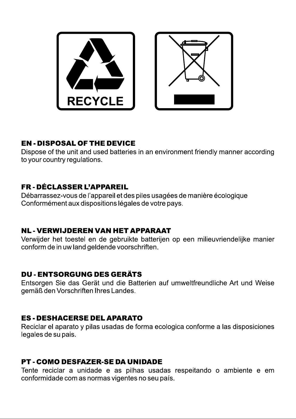
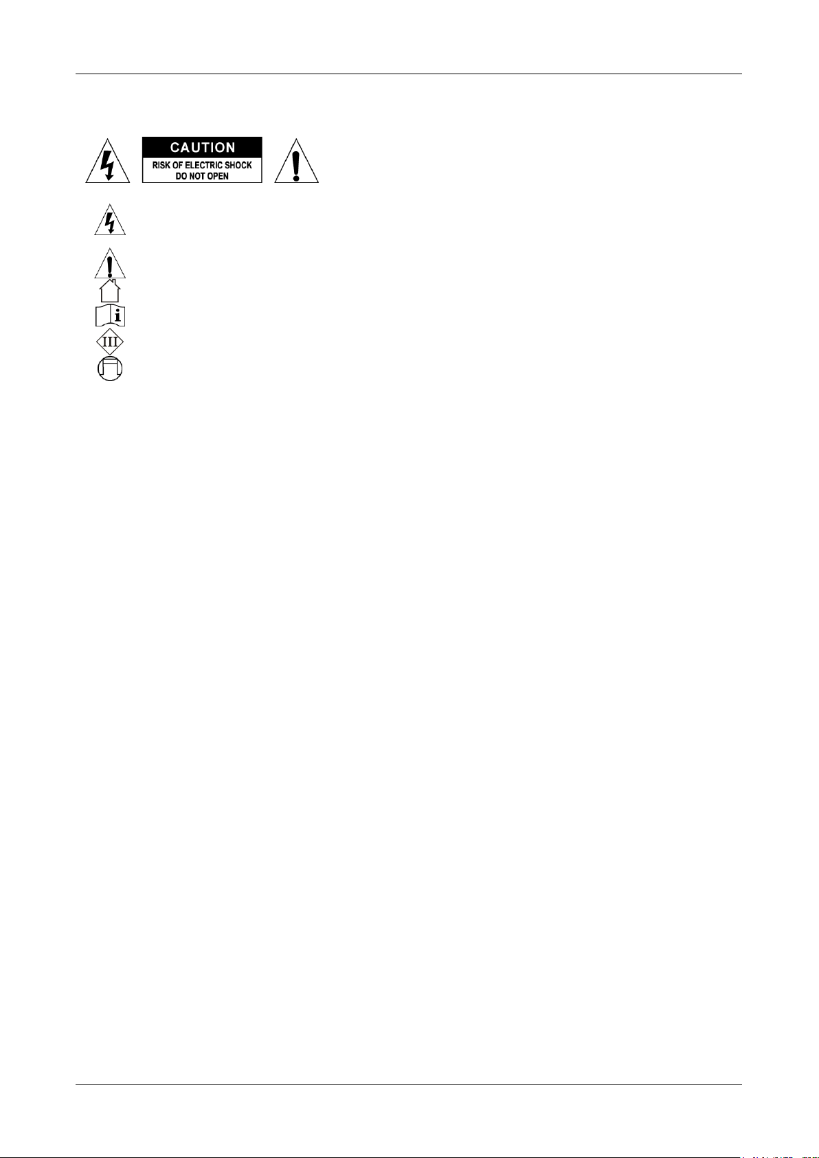
1. SEND INDICATOR: blinks while the transmitter sends commands to
the RF-receiver.
2. CONTROL BUTTONS: these 13 buttons allow the user to
independently control different light effects. Please check the chapter
SETUP AND USE for the different possible options.
3. BATTERY COMPARTMENT: the transmitter works with a small 12V
battery. (type A23 or MN21)
4. STICKER MODE: used to identify the sticker that corresponds to the
selected working mode.
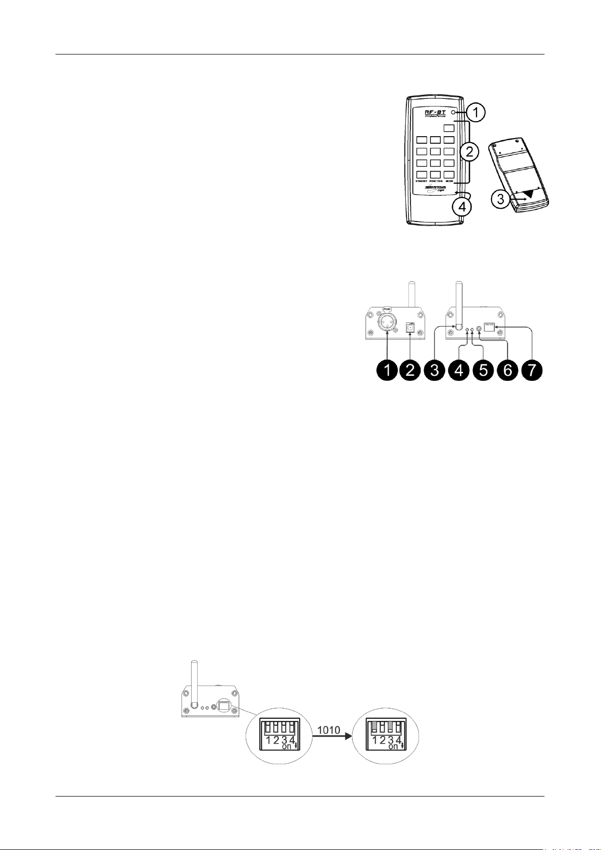
RF DMX RECEIVER FUNCTIONS (FRONT & REAR)
1. XLR 3pin CONNECTOR: to be connected to the 3pin DMX input
on the light effects.
2. DC-ADAPTER INPUT: connect the DC-adapter here.
3. RF ANTENNA: the RF antenna receives the signal transmit by
the remote control.
4. POWER LED: is lit when the RF DMX converter is on.
5. RF-SIGNAL LED: is lit while the unit receives commands from
the wireless remote. Also used to setup the receiver, see next
chapter for more information.
6. SETUP BUTTON: the transmitter should be synchronized with
the remote control. See next chapter for further explanation.
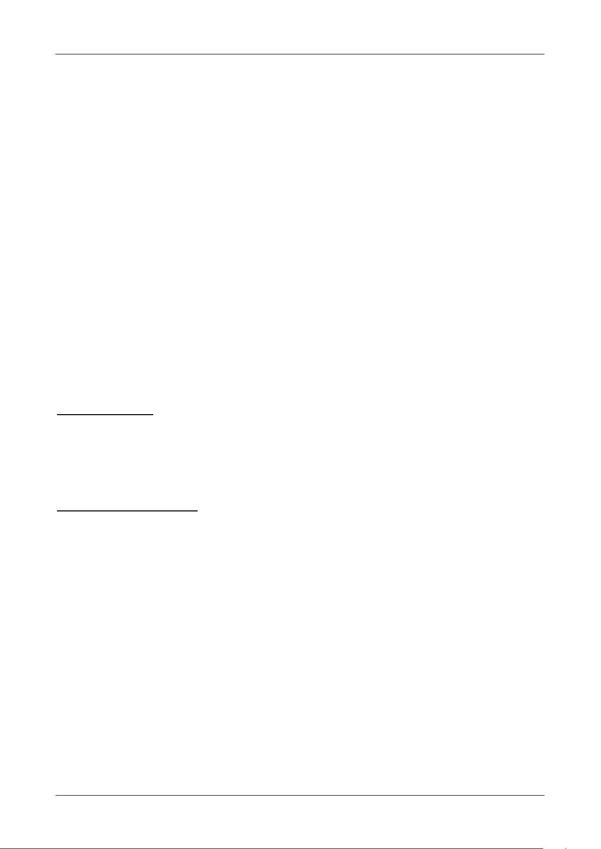
7. DIPSWITCH: The user can set up the desired DMX mode depending on the units that will be connected
to the RF DMX converter.
SETUP AND USE:
To setup the remote control, press the setup button on the RF DMX converter, then press one key on the
remote control. This operation should be done within 5 sec. During this time, the green led (RF signal LED)
is flashing. When a key is pressed on the remote control, the green led on the RF DMX converter is flashing
one more time and stops blinking directly.
If the remote is correctly synchronized with the receiver, the RF signal LED on the receiver flashes each time
a key is pressed on the remote. If it’s not working, repeat each step from the beginning.
Can be used to add wireless control to 2 types of DMX-projectors and dimmer/switch pack as well:
- Light effects using 1ch DMX mode or 1MSL, 2MSL, 3MSL or 4MSL DMX-configuration
- All LED lighting using our standard RGB+DIM DMX-configuration
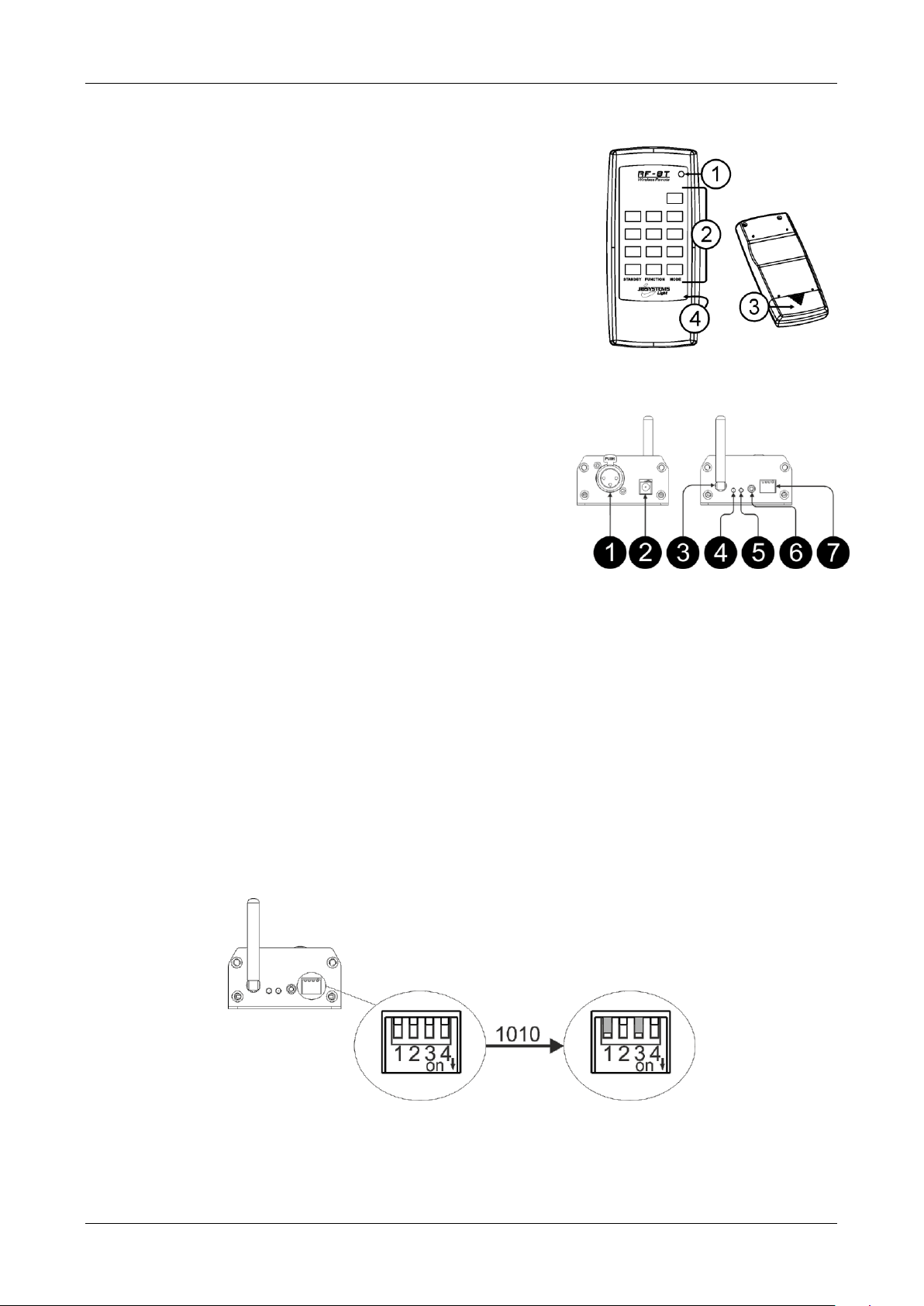
Dipswitch settings:
To setup the DMX mode, the user should set the appropriate dipswitch settings to configure the receiver:
To control these units there is 6 different working modes.
JB SYSTEMS® 3/40 RF-DMX CONVERTER
Page 6
ENGLISH OPERATION MANUAL
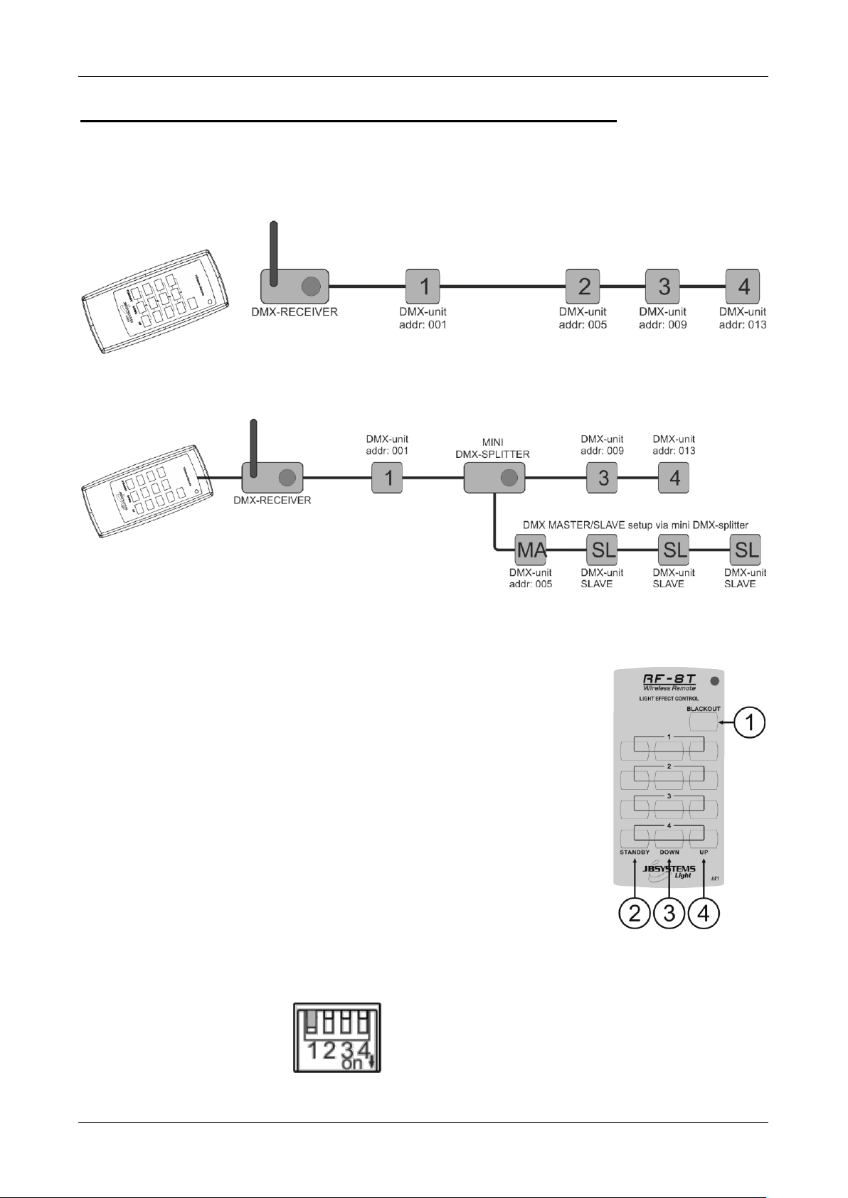
MODE 1: WITH 1MSL, 2MSL, 3MSL or 4MSL setup
Used to control light effects using 1ch DMX mode or 1MSL or 2MSL or 3MSL or 4chMSL DMXconfiguration. You can control almost all JB SYSTEMS light effects and many LED lights from Briteq.
For example, the following products are controllable by the RF DMX converter:
LED Rainbow, LED Matrix, Andromeda DMX, Genius DMX,…
Simple setup:
Note: if you want to use the 1MSL or 4MSL setup, together with other DMX-effects, just use a mini DMXsplitter! (see drawing below)
All these products should be compatible with the MODE1 of the RF-DMX converter.
Even if the connected units don’t use 4DMX-channels, the RF-DMX RECEIVER will always send out 4
channels for each of the 4 groups. As a result, the connected units should be always setup with the following
start addresses:
Unit1: start address = 001
Unit2: start address = 005
Unit3: start address = 009
Unit4: start address = 013
Mode1 uses sticker M1 for the transmitter, the sticker layout has 4 groups.
1. Blackout button: This button set every units in blackout mode
2. Standby button: switches the CH1 between 000 and last setting before
standby.
3. DOWN button: allows the user to change the show of a specific group
4. UP button: allows the user to change the show of a specific group
Effects with simple DMX on/off: the units should be always setup with the
following start addresses:
Unit1: start address = 002
Unit2: start address = 006
Unit3: start address = 010
Unit4: start address = 014
The user can switch on/off the unit using the standby button.
Dipswitch settings: 1000
JB SYSTEMS® 4/40 RF-DMX CONVERTER
Page 7
ENGLISH OPERATION MANUAL
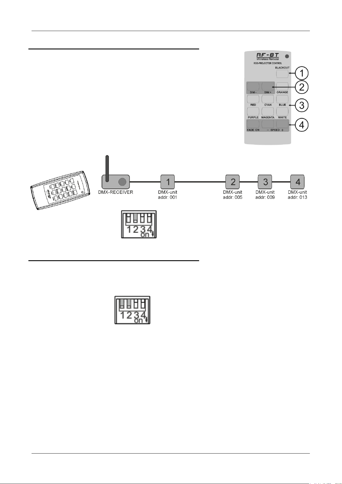
MODE 2: LED LIGHTS – RGB + Dimmer
This mode is used for architectural LED lighting and LED DMX projectors.
Channel 4 is limited to value 190, audio and strobe mode can’t be switched
on.
This mode can be used with the Planospot, LED PAR56, LDP-powerbar,…
All connected units are addressed with address = 001
Mode2 uses sticker M2 for the transmitter, the sticker layout has the following
buttons:
1. Blackout button: switches the dimmer between 000 and last setting
before standby.
2. DIM-/DIM+ buttons: used to change the master dimmer 0-100%: CH4 =
000 to 190
3. COLOR-buttons: switches the values of RGB to get the desired colors
4. FADE-buttons: The fade button toggles the fade speed.
The fade + and – buttons increase or decrease the fade speed.
Dipswitch settings: 0100
MODE 3: LED LIGHTS – RGB + Dimmer
This mode is used for LED projectors that may also go in strobe and/or sound mode. In this mode, channel 4
is NOT limited to 190, audio and strobe mode can be activated for products like the Planospot, LED
PAR56, LDP powerbar,…
Briteq architectural products could be used with this mode using the dimmer channel up to 255 without strobe
function.
Dipswitch settings: 1100
The rest is identical to MODE2.
JB SYSTEMS® 5/40 RF-DMX CONVERTER
Page 8
ENGLISH OPERATION MANUAL
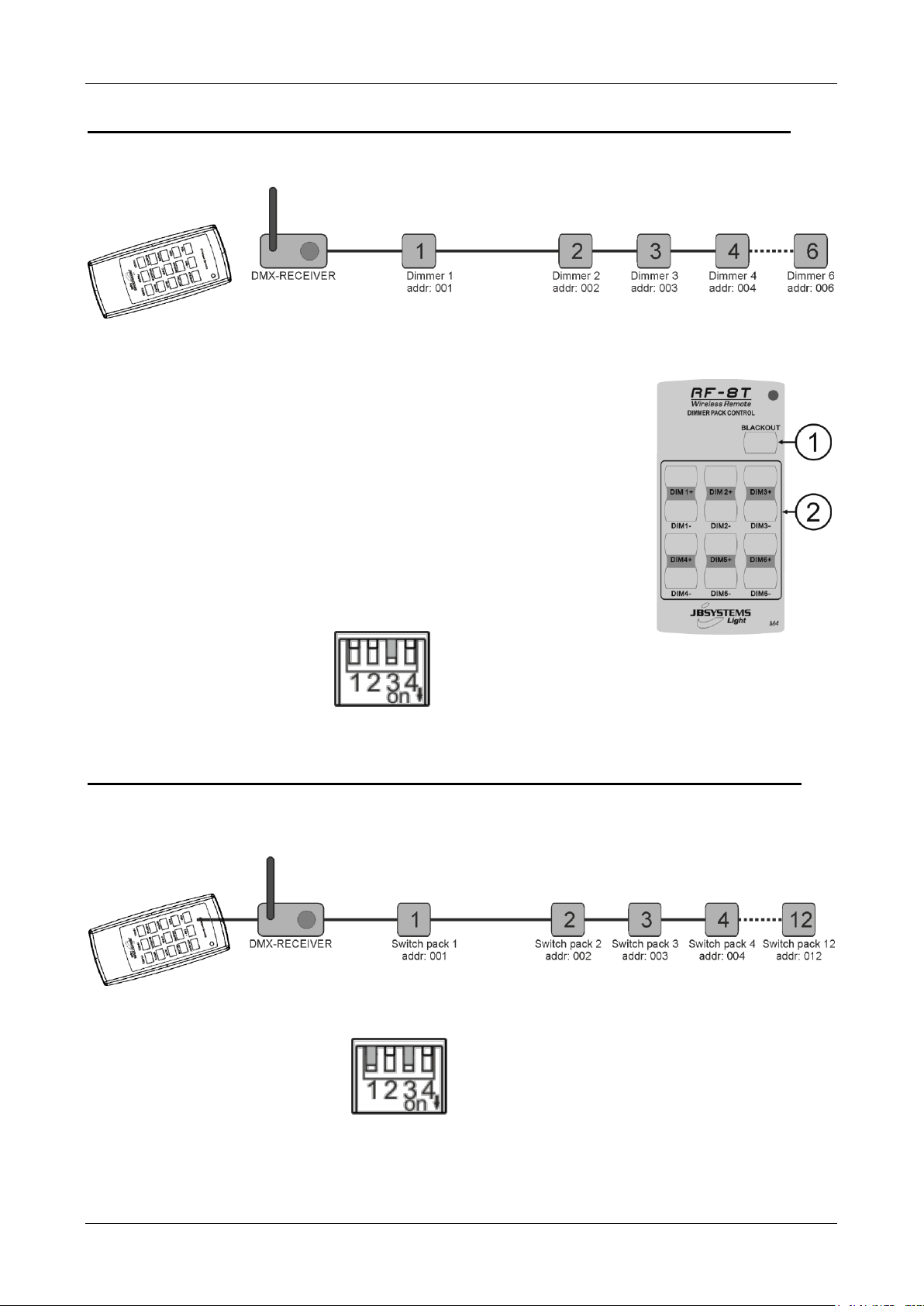
MODE 4: CONTROLLING DIMMER PACKS WITH UP TO 6CH
Used to control standard DMX dimmer packs with max 6 channels. Each channel of this dimmer pack uses 1
DMX channel. The RF DMX converter can control a DX626A for example.
For each of the 6 groups on the remote, the RF-DMX RECEIVER will always send out 1channel so the
connected units should be always setup with the following start addresses:
Unit1: start address = 001
Unit2: start address = 002
Unit3: start address = 003
Unit4: start address = 004
Unit5: start address = 005
Unit6: start address = 006
If you use a 6CH dimmer pack, the start address should be set at 001. Mode4
uses sticker M4 for the transmitter, buttons on the RF-remote work as follows:
1. Blackout: switches the output between 000 (output = off) and the last
value that has been set previously with the DIM+/DIM- buttons.
2. DIM+ button as long as you press the button, the DMX-value will
increase until it reaches the maximum value of 255.
DIM- button as long as you press the button, the DMX-value will
decrease until it reaches the minimum of 000.
Dipswitch settings: 0010
MODE 5: CONTROLLING SWITCH PACKS WITH UP TO 12CH
Used to control standard DMX switch packs with max 12 channels. Each channel of such switch pack uses 1
DMX channel. The RF DMX converter can control for example the following products:
DSP12, DSP4,…
Dipswitch settings: 1010
JB SYSTEMS® 6/40 RF-DMX CONVERTER
Page 9
ENGLISH OPERATION MANUAL
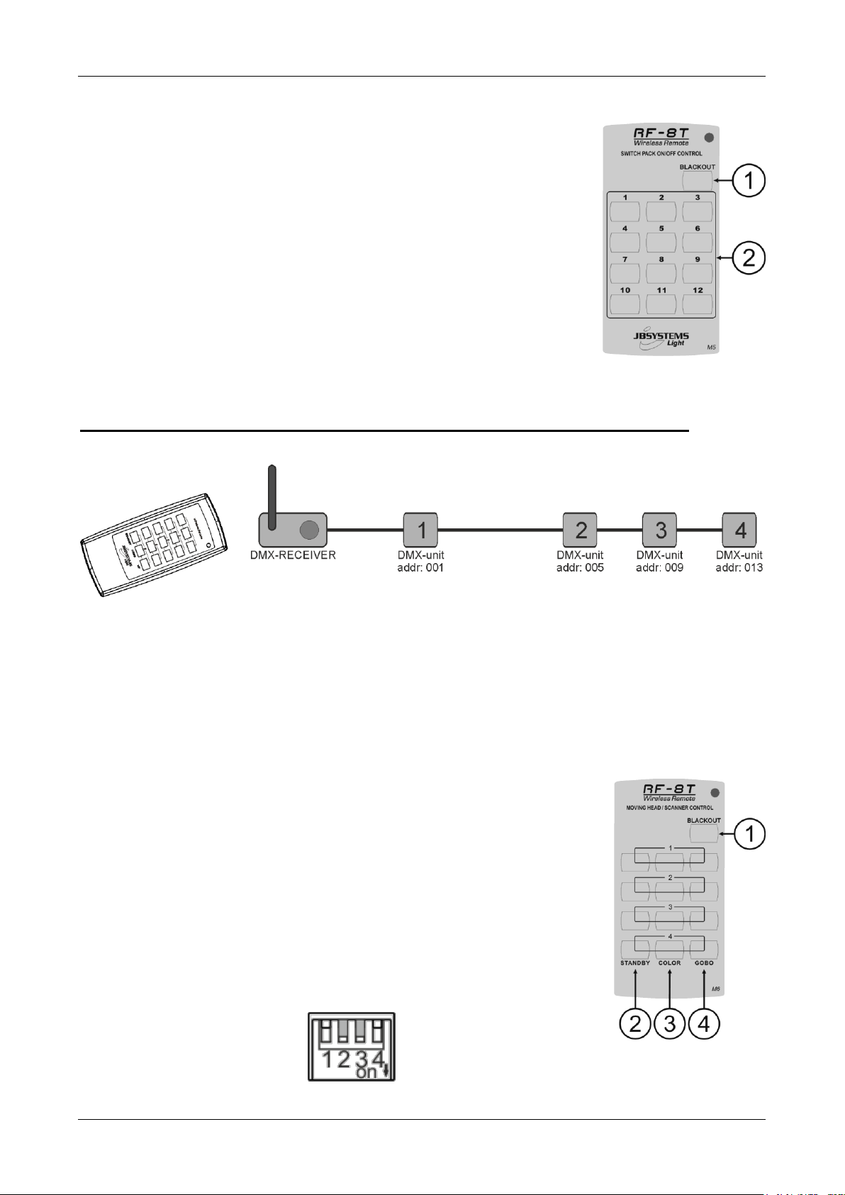
The RF-DMX RECEIVER will send out 12 channels of switch pack.
The connected units should be always setup with the following start
addresses:
Unit1: start address = 001
Unit2: start address = 002
Unit3: start address = 003
Unit4: start address = 004
Unit5: start address = 005
…
Unit12: start address = 012
Mode5 uses sticker M5 for the transmitter, the sticker layout has the following
buttons.
The remote has 12 identical toggle buttons and one blackout button:
1. Blackout: switches the output between 000 (output = off) and the last
value that has been set previously.
2. Toggle Button: Switch the unit on: DMX-value = 255
Switch the unit off: DMX-value = 000
MODE6: MAINLY FOR SCANNERS AND MOVING HEADS
Used to control light effects using 4ch DMX mode or 4chMSL DMX configuration
This mode allows the RF DMX converter to control light effects like the LED Pulsar, LED Microscan,
BT60LS, Sirius,…
All these products should be compatible with the MODE 6 of the RF-DMX converter independently on the
number of channels (1,2,3 or 4). Even if the connected units don’t use 4 DMX-channels, the RF-DMX
RECEIVER will always send out 4channels. As result, the connected units should be always setup with the
following start addresses:
Unit1: start address = 001
Unit2: start address = 005
Unit3: start address = 009
Unit4: start address = 013
Mode 6 uses sticker M6 for the transmitter, the sticker layout has 4 group:
1. Blackout: switches the output between 000 (output = off) and the last value
that has been set previously.
2. Standby button: If you press this button, the RF-DMX converter will toggle
the standby mode of the selected unit depending on its previous state. If you
press the button more than 1s, the fixture will go in fast strobe mode.
3. Color-button: If you press this button, the RFDMX converter will change the
colors. If you press the button more than 1s, the fixture will use the original
colors of the show.
4. Gobo-button: If you press this button, the RF-DMX converter will change
the gobos. If you press the button more than 1s, the fixture will use the
original gobos of the show.
Dipswitch settings: 0110
JB SYSTEMS® 7/40 RF-DMX CONVERTER
Page 10
ENGLISH OPERATION MANUAL
MAINTENANCE
Clean by wiping with a polished cloth slightly dipped with water. Avoid getting water inside the unit. Do not
use volatile liquids such as benzene or thinner which will damage the unit.
SPECIFICATIONS
Power Input: DC 9V 300mA minimum.
AC/DC Power adapter: AC 230V, 50Hz 9Vdc / 300mA (or more)
DMX outputs: 3pin XLR
Audio input: None
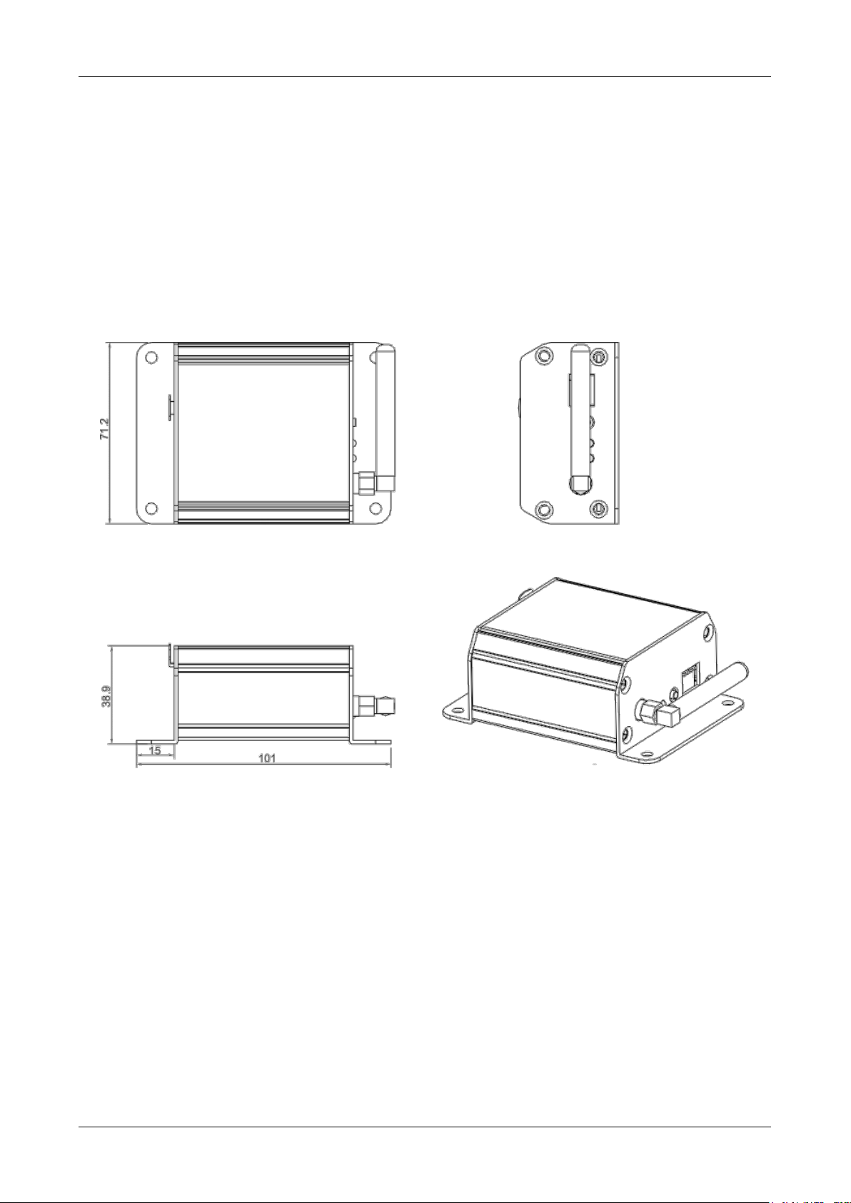
Size: 10.1 x 7.2 x 3.9 cm
Weight: 0,14 kg
Every information is subject to change without prior notice
You can download the latest version of this user manual on our website: www.beglec.com
JB SYSTEMS® 8/40 RF-DMX CONVERTER
Page 11
FRANÇAIS GUIDE D'UTILISATION
GUIDE D'UTILISATION
Nous vous remercions d'avoir acheté ce produit JB Systems®. Lisez ce guide d'utilisation très attentivement
pour tirer pleinement profit de toutes les possibilités de l'appareil.
CARACTÉRISTIQUES
Cet appareil ne produit pas d’interférences radio. Ce produit répond aux exigences des directives
européennes et nationales actuelles. La conformité a été établie et les déclarations et documents
correspondants ont été déposés par le fabricant.
Télécommande sans fil pour tout jeu de lumière DMX et/ou projecteur DMX.
Les commandes issues de la télécommande sans fil sont converties en signaux DMX pour contrôler divers
appareils DMX.
Cet ensemble contient 2 éléments :
Une petite télécommande sans fil avec 13 touches et des autocollants pour les différents modes de
fonctionnement
Un récepteur sans fil doté d’une sortie DMX XLR à 3 broches.
Différentes configurations de canaux DMX sont préprogrammées pour une utilisation avec divers
projecteurs/jeux de lumière DMX.
Compatible avec notre gamme LED MANAGER, la série LD/LDP de Briteq®, les packs
gradateurs/interrupteurs et la plupart de nos jeux de lumière DMX, y compris ceux à têtes mobiles.
D’autres configurations de canaux DMX peuvent être téléchargées pour s’assurer de la compatibilité avec
les Technologies d'avenir.
Portée maximale : jusqu'à 100m
Fréquence de fonctionnement : 433,92MHz
Connecteur de données : XLR 3 broches
AVANT UTILISATION
Vérifiez le contenu :
Vérifiez que le carton contient les articles suivants :
Emetteur sans fil doté de 13 touches
Convertisseur RF-DMX
Emetteur RF-DMX (télécommande sans fil)
Adaptateur d'alimentation CA/CC 9V
Guide d'utilisation
Quelques instructions importantes :
Avant d'utiliser cet appareil, vérifiez s'il n'a pas été endommagé durant le transport. En cas de dommages,
n'utilisez pas l'appareil et consultez immédiatement votre revendeur.
Important : Cet appareil est expédié de notre usine en parfait état et bien emballé. Il est absolument
nécessaire que l'utilisateur suive strictement les instructions et les avertissements de sécurité se trouvant
dans ce manuel. Tout dommage dû à une mauvaise manipulation n'est pas garanti. Le revendeur
n'accepte aucune responsabilité pour tous les défauts et problèmes dus au non respect de ce manuel.
Conservez ce manuel dans un endroit sûr pour toute consultation future. Si vous vendez l'appareil, veillez
à joindre ce manuel.
Pour protéger l'environnement, essayer de recycler autant que possible les matériaux d'emballage.
JB SYSTEMS® 9/40 RF-DMX CONVERTER
Page 12
FRANÇAIS GUIDE D'UTILISATION
ATTENTION : Pour réduire le risque de choc électrique,
ne retirez pas le panneau supérieur. L'appareil ne contient
aucun composant réparable par l'utilisateur. Confiez toute
réparation à un personnel qualifié uniquement.
Le symbole de l'éclair à l'intérieur d'un triangle équilatéral, est destiné à alerter l'utilisateur de la
présence de pièces sous tension non isolées dans le boîtier de l'appareil, d'une magnitude
pouvant constituer un risque d'électrocution.
Le symbole du point d'exclamation dans un triangle sert à avertir l'utilisateur que d'importants
conseils de fonctionnement sont fournis dans la documentation
Ce symbole signifie : pour usage intérieur uniquement.
Ce symbole signifie : Lisez les instructions
Ce symbole signifie : Appareil de classe de sécurité III
Ce symbole signifie : Appareillage d’alimentation de lampe
INSTRUCTIONS DE SÉCURITÉ :
Pour éviter tout incendie ou électrocution, n'exposez pas cet appareil à la pluie ou l'humidité.
Pour éviter une formation de condensation interne, laissez l'appareil s'adapter à la température ambiante
quand vous la mettez dans une pièce chauffée après le transport. La condensation empêche parfois
l'appareil de fonctionner à plein rendement ou peut même causer des dommages.
Cet appareil est destiné à un usage intérieur seulement.
Ne placez pas d'objets métalliques et ne renversez pas de liquides à l'intérieur de l'appareil. Aucun objet
rempli de liquide, tel que des vases, ne doit être placé au dessus de l'appareil. Un choc électrique ou un
dysfonctionnement peut en résulter. Si un corps étranger pénètre dans l'appareil, débranchez
immédiatement l'alimentation secteur.
Aucune source de flamme nue, telle que des bougies allumées, ne doit être placée au dessus de
l'appareil.
Ne couvrez pas les ouvertures de ventilation, cela pourrait entraîner une surchauffe.
Evitez une utilisation dans des environnements poussiéreux et nettoyez l'appareil régulièrement.
Gardez l'appareil loin de la portée des enfants.
Les personnes inexpérimentées ne doivent pas utiliser cet appareil.
La température ambiante de fonctionnement maximale est de 40°C. N'utilisez pas cet appareil à des
températures ambiantes plus élevées.
Débranchez toujours l'appareil lorsqu'il ne va pas être utilisé pendant une longue période et avant chaque
entretien.
L'installation électrique doit être effectuée par du personnel qualifié, conformément à la réglementation en
matière de sécurité électrique et mécanique dans votre pays.
Vérifiez que votre tension n'est pas supérieure à celle indiquée sur le panneau arrière de l'appareil.
La prise d'entrée doit rester accessible pour le débranchement du secteur.
Le cordon d'alimentation doit toujours être en parfait état. Eteignez immédiatement l'appareil dès le cordon
d'alimentation est écrasé ou endommagé. Il doit être remplacé par le fabricant, son agent de service ou
une personne de même qualification afin d'éviter tout danger.
Ne laissez jamais le cordon d'alimentation entrer en contact avec d'autres câbles !
Pour éviter tout danger, l'appareil ne doit être utilisé qu'avec l'adaptateur secteur fourni. Si l'adaptateur
secteur est endommagé, vous ne devez utiliser qu'un adaptateur de même modèle.
Afin d'éviter un choc électrique, n'ouvrez aucun panneau. A part la lampe et le fusible, il n'y a aucune pièce
réparable par l'utilisateur.
Ne réparez jamais un fusible et ne court-circuitez jamais le porte-fusible. Remplacez toujours un fusible
endommagé par un fusible du même type ayant les mêmes spécifications électriques !
En cas de sérieux problèmes de fonctionnement, cessez d'utiliser l'appareil et contactez immédiatement
votre revendeur.
Utilisez l'emballage d'origine pour transporter l'appareil.
Pour des raisons de sécurité, il est interdit d'apporter des modifications non autorisées à l'appareil.
JB SYSTEMS® 10/40 RF-DMX CONVERTER
Page 13
FRANÇAIS GUIDE D'UTILISATION
FONCTIONS DE L'ÉMETTEUR SANS FIL
1. INDICATEUR D’ÉMISSION : clignote lorsque l'émetteur envoie des
commandes vers le récepteur RF.
2. TOUCHES DE COMMANDE : Ces 13 touches permettent à
l'utilisateur de contrôler les différents effets de lumière de façon
indépendante. Reportez-vous au chapitre CONFIGURATION ET
UTILISATION pour connaître les différentes options possibles.
3. COMPARTIMENT DES PILES : L’émetteur fonctionne avec une petite
batterie 12V. (type A23 ou MN21)
4. Mode de l’autocollant : Le mode d’utilisation de l’autocollant est
indiqué lisiblement dans ce coin.
FONCTIONS DU RECEPTEUR RF-DMX
1. CONNECTEUR XLR 3 BROCHES : à connecter à l'entrée DMX 3 broches des jeux de lumière.
2. ENTREE ADAPTATEUR CC : Branchez l'adaptateur secteur ici.
3. ANTENNE RF : l'antenne RF reçoit le signal émis par la
télécommande.
4. TEMOIN D'ALIMENTATION : est allumé lorsque le
convertisseur RF-DMX est allumé.
5. VOYANT DU SIGNAL RF : est allumé lorsque l'appareil reçoit
les commandes de la télécommande sans fil. Également
utilisé pour la configuration du récepteur, reportez-vous au
chapitre suivant pour plus d'informations.
6. TOUCHE SETUP (Configuration) : l'émetteur doit être
synchronisé avec la télécommande. Reportez-vous au chapitre suivant pour plus d'informations.
7. COMMUTATEUR DIP : L'utilisateur peut configurer le mode DMX souhaité en fonction des unités qui
seront connectées au convertisseur RF-DMX.
CONFIGURATION ET UTILISATION :
Pour configurer la télécommande, appuyez sur la touche de configuration setup du convertisseur RF-DMX,
puis appuyez sur une touche de télécommande. Cette opération doit être effectuée dans les 5 secondes.
Pendant ce temps, le voyant vert (voyant du signal RF) clignote. Quand une touche de la télécommande est
appuyée, le voyant vert du convertisseur RF-DMX clignote une autre fois puis s'arrête de clignoter.
Si la télécommande est correctement synchronisée avec le récepteur, le voyant du signal RF du récepteur
clignote à chaque fois qu'une touche de la télécommande est appuyée. Si ça ne marche pas, répétez
chaque étape depuis le début.
Peut être utilisée pour ajouter un contrôle sans fil à 2 types de projecteurs DMX et des packs
gradateur/interrupteur :
- Les effets de lumière utilisant le mode DMX 1ch ou la configuration DMX 1MSL, 2MSL, 3MSL ou
4MSL
- Tout éclairage à LED utilisant notre configuration DMX standard RVB + DIM
Paramètres du commutateur DIP :
Pour configurer le mode DMX, l'utilisateur doit définir les paramètres appropriés du commutateur DIP pour
configurer le récepteur :
JB SYSTEMS® 11/40 RF-DMX CONVERTER
Page 14

FRANÇAIS GUIDE D'UTILISATION
Il y a 6 différents modes de fonctionnement pour contrôler ces unités:
MODE 1 : AVEC LA CONFIGURATION 1MSL, 2MSL, 3MSL ou 4MSL
Utilisé pour contrôler les effets de lumière en utilisant le mode DMX 1ch ou la configuration DMX 1MSL ou
2MSL ou 3MSL ou 4chMSL. Vous pouvez également contrôler presque tous les effets de lumière JB
SYSTEMS et beaucoup de lumières à LED de Briteq.
Par exemple, les produits suivants sont contrôlables par le convertisseur RF-DMX : LED Rainbow, LED
Matrix, Andromeda DMX, Genius DMX…
Configuration simple :
Remarque : il suffit d'utiliser un mini répartiteur DMX pour pouvoir utiliser une configuration 1MSL à 4MSL,
avec d'autres effets DMX 1ch ! Voir dessin ci-dessous
Tous ces produits doivent être compatibles avec le MODE1 du convertisseur RF-DMX.
Même si les unités connectées n’utilisent pas DMX 4 canaux, le récepteur RF-DMX envoie toujours 4
canaux pour chacun des 4 groupes. Ainsi les unités connectées doivent toujours être configurées avec les
adresses de début suivantes :
Unité 1 : adresse de début = 001
Unité 2 : adresse de début = 005
Unité 3 : adresse de début = 009
Unité 4 : adresse de début = 013
Mode1 utilise sticker M1 pour l'émetteur, la disposition autocollant a 4 groupes.
1. Touche Blackout : Cette touche fixé fait passer chaque unité en mode
blackout
2. Touche STANDBY (Veille) : Commute CH1 entre 000 et le dernier réglage
avant le mode veille.
3. Touche vers le Bas : permet à l'utilisateur de changer le show d'un certain
groupe
4. Touche vers le Haut : permet à l'utilisateur de changer le show d'un certain
groupe
Les effets avec simple DMX on/off: les unités doivent toujours être configurées avec les adresses de
début suivantes :
Unité 1 : adresse de début = 002
Unité 2 : adresse de début = 006
Unité 3 : adresse de début = 010
Unité 4 : adresse de début = 014
JB SYSTEMS® 12/40 RF-DMX CONVERTER
Page 15

FRANÇAIS GUIDE D'UTILISATION
L'utilisateur peut activer/désactiver l’unité en utilisant le bouton veille.
Paramètres du commutateur DIP : 1000
MODE 2 : LUMIERE A LED - RGB + GRADATEUR
Ce mode est utilisé pour les lumières à LED de décoration et projecteurs à LED
DMX. Le mode 4 canaux est limité à 190, le mode audio et stroboscopique peut
ne pas fonctionner. Le gradateur est limité à 190.
Ce mode peut être utilisé avec Planospot, LED PAR56, LDP powerbar .
Tous les unités connectées ont l'adresse = 001
Mode2 utilise le sticker M2 pour l'émetteur, la disposition autocollant dispose des
touches suivantes :
1. Touche Blackout : Commute le gradateur entre 000 et le dernier réglage
avant le mode veille.
2. Touches DIM-/DIM+ : permet de changer le gradateur principal de 0 à 100%
: CH4 = 000 à 190
3. Touches couleur : Commute les valeurs RGB pour obtenir les couleurs
souhaitées
4. Touche FADE (Fondu) : Permet de changer la vitesse de fondu. Le fondu +
et - augmente ou diminue la vitesse de fondu.
Paramètres du commutateur DIP : 0100
MODE 3 : LUMIERE A LED - RGB + GRADATEUR
Ce mode est utilisé pour les projecteurs à LED qui peuvent fonctionner en mode stroboscopique et/ou audio.
Dans ce mode, le canal 4 n'est pas limité à 190, le mode audio et stroboscopique peut être activé pour
des produits tels que Planospot, LED PAR56, LDP-Powerbar...
Les produits de décoration Briteq peuvent être utilisés avec ce mode en utilisant le canal gradateur jusqu'à
255 sans fonction stroboscopique.
Paramètres du commutateur DIP : 1100
Le reste est identique à MODE 2.
JB SYSTEMS® 13/40 RF-DMX CONVERTER
Page 16

FRANÇAIS GUIDE D'UTILISATION
MODE 4: CONTRÔLE DES PACKS GRADATEURS AVEC 6CAN
Utilisé pour contrôler les packs gradateurs DMX avec 6 canaux maximum. Chaque canal de ce pack
gradateurs utilise un canal DMX. Le convertisseur RF-DMX peut par exemple contrôler un DX626A.
Pour chacun des 6 groupes de la télécommande, le récepteur RF-DMX envoie toujours 1 canal de
manière que les unités connectées soient toujours configurées avec les adresses de début suivantes :
Unité 1 : adresse de début = 001
Unité 2 : adresse de début = 002
Unité 3 : adresse de début = 003
Unité 4 : adresse de début = 004
Unité 5 : adresse de début = 005
Unité 6 : adresse de début = 006
Si vous utilisez un pack gradateurs 6 canaux, l'adresse de départ doit être fixée à
001. Mode4 utilise sticker M4 pour l'émetteur, les touches de la télécommande RF
sont les suivantes :
1. Blackout commute la sortie entre 000 (sortie = désactivée) et la dernière
valeur qui a été fixée préalablement avec les touches DIM+/DIM-.
2. Touche DIM+ tant que vous appuyez sur cette touche, la valeur DMX va
augmenter jusqu'à ce qu'elle atteigne la valeur maximale de 255.
Touche DIM- tant que vous appuyez sur cette touche, la valeur DMX va
diminuer jusqu'à ce qu'elle atteigne la valeur maximale de 000.
Paramètres du commutateur DIP : 0010
MODE 5 : CONTRÔLE DES PACKS GRADATEURS AVEC 12
CANAUX MAXIMUM
Utilisé pour contrôler les packs commutateurs DMX avec 12 canaux maximum. Chaque canal de ce pack
commutateurs utilise un canal DMX. Le Convertisseur RF-DMX peut contrôler par exemple les produits
suivants : DSP12, DSP4…
Paramètres du commutateur DIP : 1010
JB SYSTEMS® 14/40 RF-DMX CONVERTER
Page 17

FRANÇAIS GUIDE D'UTILISATION
Le récepteur RF-DMX envoie 12 canaux du pack commutateurs.
Les unités doivent toujours être configurées avec les adresses de début suivantes :
Unité 1 : adresse de début = 001
Unité 2 : adresse de début = 002
Unité 3 : adresse de début = 003
Unité 4 : adresse de début = 004
Unité 5 : adresse de début = 005
…
Unité 12 : adresse de début = 012
Mode5 utilise sticker M5 pour l'émetteur, la disposition autocollant dispose des
touches suivantes :
La télécommande dispose de touches 12 identiques et une touche blackout :
1. Blackout commute la sortie entre 000 (sortie = désactivée) et la dernière
valeur qui a été fixée préalablement.
2. Touche bascule : Allume l'appareil : Valeur DMX= 255
Eteint l'appareil : Valeur DMX = 000
MODE 6 : PRINCIPALEMENT POUR LES SCANNERS ET LYRES
Utilisé pour contrôler les effets de lumière en utilisant le mode DMX 4 canaux ou la configuration DMX 4MSL
Ce mode permet au convertisseur RF-DMX de contrôler les effets de lumière tels que LED Pulsar, LED
Microscan, BT60LS, Sirius…
Tous ces produits doivent être compatibles avec le MODE 6 du convertisseur RF-DMX indépendamment du
nombre de canaux (1, 2, 3 ou 4). Même si les unités connectées n’utilisent pas DMX 4 canaux, le récepteur
RF-DMX envoie toujours 4 canaux. Ainsi les unités connectées doivent toujours être configurées avec les
adresses de début suivantes :
Unité 1 : adresse de début = 001
Unité 2 : adresse de début = 005
Unité 3 : adresse de début = 009
Unité 4 : adresse de début = 013
Mode 6 utilise autocollant M6 pour l'émetteur, la disposition des autocollants a 4
groupes :
1. Blackout commute la sortie entre 000 (sortie = désactivée) et la dernière
valeur qui a été fixée préalablement.
2. Touche STANDBY (Veille) : Si vous appuyez sur cette touche, le
convertisseur RF-DMX permet de basculer le mode veille de l'unité
sélectionnée en fonction de son état précédent. Si vous appuyez pendant plus
d’une seconde sur la touche, l'appareil va passer en mode stroboscopique
rapide.
3. Touche COLOR : Si vous appuyez sur cette touche, le convertisseur RF-DMX
va changer de couleur. Si vous appuyez pendant plus d’une seconde sur la
touche, l'appareil utilise la couleur originale du show.
4. Touches GOBO: Si vous appuyez sur cette touche, le convertisseur RF-DMX
va changer le gobo. Si vous appuyez pendant plus d’une seconde sur la
touche, l'appareil utilise le gobo original du show.
Paramètres du commutateur DIP : 0110
JB SYSTEMS® 15/40 RF-DMX CONVERTER
Page 18

FRANÇAIS GUIDE D'UTILISATION
ENTRETIEN
Nettoyez l'appareil à l'aide d'un chiffon légèrement humidifié. Évitez que l'eau ne pénètre à l'intérieur de
l'appareil. N'utilisez pas de liquides volatils tels que benzène ou diluant qui endommagent l'appareil.
SPÉCIFICATIONS
Alimentation d’entrée : CC 9V 300mA minimum.
Adaptateur d'alimentation CA/CC : AC 230V, 50Hz 9Vdc/300mA (ou plus)
SORTIE DMX : XLR 3 broches
Entrée audio : Aucune
Dimensions : 10,1 x 7,2 x 3,9 cm
Poids : 0,14 kg
Toutes les informations peuvent être modifiées sans préavis
Vous pouvez télécharger la dernière version de ce manuel sur notre site web : www.beglec.com
JB SYSTEMS® 16/40 RF-DMX CONVERTER
Page 19

NEDERLANDS GEBRUIKSAANWIJZING
GEBRUIKSAANWIJZING
Hartelijk dank voor de aankoop van dit JB SYSTEMS® product. Om volledig van alle mogelijkheden te
profiteren, lees deze handleiding zeer zorgvuldig.
KENMERKEN
Dit apparaat is radio-interferentie onderdrukt. Dit product voldoet aan de eisen van de huidige Europese en
nationale richtlijnen. Overeenstemming is vastgesteld en de desbetreffende verklaringen en documenten zijn
door de fabrikant gedeponeerd.
Draadloze afstandsbediening voor alle soorten DMX-lichteffecten en/of DMX-projectoren.
Opdrachten van uw draadloze handbediening worden vertaald naar DMX signalen om verschillende DMX-
apparatuur te besturen.
Deze set bestaat uit 2 delen:
Een kleine, draadloze afstandsbediening met 13 knoppen en stickers voor verschillende werkmodi.
Een draadloze ontvanger met een 3-pins XLR DMX -uitgang.
Verschillende DMX-kanaalinstellingen zijn voorgeprogrammeerd voor gebruik met verschillende DMX-
projectoren/effecten.
Compatibel met onze LED-managerassortiment, LD/LDP-serie van Briteq®, dimmer/schakelaarpakket en
de meeste van onze DMX-effecten, inclusief bewegende koppen.
Extra DMX-kanaalinstellingen kunnen worden geüpload voor maximale "toekomstbestendige"
compatibiliteit.
Maximale werkafstand: maximaal 100 m
Werkfrequentie: 433,92 MHz
Dataconnector: XLR 3-pin
VÓÓR GEBRUIK
Controleer de inhoud:
Controleer of de kartonnen doos de volgende items bevat:
Draadloze zender met 13 knoppen
RF DMX-convertor
RF-DMX-zender (draadloze afstandsbediening)
AC/DC-voeding 9 V
Gebruikershandleiding
Enkele belangrijke veiligheidsinstructies
Voordat u met het gebruik van dit apparaat start, controleer of er geen transportschade aanwezig is. Mocht
er schade zijn, gebruik het apparaat niet en raadpleeg eerst uw dealer.
Belangrijk: Dit apparaat verliet de fabriek in perfecte staat en goed verpakt. Het is absoluut noodzakelijk
voor de gebruiker om de veiligheidsinstructies en waarschuwingen in deze handleiding strikt op te volgen.
Eventuele schade veroorzaakt door verkeerd gebruik valt niet onder de garantie. De dealer zal niet
aansprakelijk worden gesteld voor eventuele fouten of problemen veroorzaakt door het negeren van deze
handleiding.
Bewaar dit boekje op een veilige plaats voor toekomstige raadpleging. Als u de armatuur verkoopt, zorg
ervoor deze handleiding erbij te voegen.
Om het milieu te beschermen, probeer het verpakkingsmateriaal zoveel mogelijk te recyclen.
JB SYSTEMS® 17/40 RF-DMX CONVERTER
Page 20

NEDERLANDS GEBRUIKSAANWIJZING
OPGELET: Om het risico voor elektrische schokken te
verkleinen, verwijder de bovenafdekking niet. Binnenin
bevinden zich geen onderdelen die door de gebruiker
onderhouden kunnen worden. Laat het onderhoud door
gekwalificeerde onderhoudspersoneel uitvoeren.
De bliksemschicht met pijl binnenin een gelijkzijdige driehoek is bedoeld om de gebruiker te
waarschuwen op de aanwezigheid van ongeïsoleerde “gevaarlijke voltage” binnen de behuizing
van het product dat van voldoende omvang is om een risico op elektrische schokken te vormen.
Het uitroepteken binnen een gelijkzijdige driehoek is bedoeld om de gebruiker te waarschuwen
op de aanwezigheid van belangrijke gebruiks- en onderhoudsinstructies in de documentatie die
met dit apparaat meekomen.
Dit symbool betekent: alleen gebruik binnenshuis
Dit symbool betekent: Lees de instructies
Dit symbool betekent: Veiligheidsklasse III apparaat.
Dit symbool betekent: Lampbesturingapparatuur
VEILIGHEIDSINSTRUCTIES:
Om vuur of elektrische schokgevaar te voorkomen, stel dit apparaat niet bloot aan regen of vocht.
Om te voorkomen dat binnenin condensatie wordt gevormd, laat het apparaat aan de
omgevingstemperatuur aanpassen wanneer het na transport in een warme kamer wordt gebracht.
Condens verhindert soms het apparaat op volle capaciteit te werken of kan zelfs schade veroorzaken.
Dit apparaat is uitsluitend geschikt voor gebruik binnenshuis.
Plaats geen metalen voorwerpen of mors geen vloeistoffen in het toestel. Geen objecten gevuld met
vloeistoffen, zoals vazen, mogen op dit apparaat worden geplaatst. Elektrische schokken of storing kan het
gevolg zijn. Als een vreemd voorwerp in het apparaat terechtkomt, trek onmiddellijk de stekker uit het
stopcontact.
Plaats geen voorwerpen met open vuur, zoals brandende kaarsen, op het apparaat.
Bedek geen ventilatieopeningen, omdat het tot oververhitting kan leiden.
Voorkom het gebruik in stoffige omgevingen en maak het regelmatig schoon.
Houd het apparaat buiten bereik van kinderen.
Onervaren personen mogen dit apparaat niet bedienen.
De maximaal veilige omgevingstemperatuur is 40 °C. Gebruik deze unit niet bij hogere
omgevingstemperaturen.
Ontkoppel altijd het apparaat wanneer het voor een langere tijd niet wordt gebruikt of alvorens het
onderhoud te beginnen.
De elektrische installatie dient alleen door gekwalificeerd personeel te worden uitgevoerd, in
overeenstemming met de voorschriften voor elektrische en mechanische veiligheid in uw land.
Controleer of de beschikbare spanning niet hoger is dan aangegeven op het achterpaneel van het
apparaat.
De aansluitingingang zal voor het afsluiten van het lichtnet bedienbaar blijven.
Het netsnoer moet altijd in perfecte staat zijn. Schakel het apparaat onmiddellijk uit als het netsnoer wordt
platgedrukt of beschadigd. Als het netsnoer beschadigd is, moet deze door de fabrikant, zijn
vertegenwoordiger, of door een vergelijkbaar bevoegd persoon worden vervangen, om een gevaar te
voorkomen.
Laat het netsnoer nooit met andere kabels in contact komen!
Om gevaar te voorkomen, mag het apparaat alleen met de meegeleverde AC-adapter worden gebruikt.
Als de AC-adapter is beschadigd, mag alleen een zelfde model adapter worden gebruikt.
Om elektrische schokken te voorkomen, open de afdekking niet. Afgezien van de lamp en de zekering zijn
er geen te onderhouden onderdelen binnenin aanwezig.
Repareer nooit een zekering of sluit nooit de zekeringhouder kort. Vervang altijd een kapotte zekering
met een zekering van hetzelfde type en elektrische specificaties!
In het geval van ernstige problemen, stop met het gebruik van het apparaat en neem onmiddellijk contact
op met uw dealer.
Gebruik de originele verpakking als het toestel vervoerd moet worden.
Vanwege veiligheidsredenen is het verboden om ongeautoriseerde wijzigingen op het apparaat aan te
brengen.
JB SYSTEMS® 18/40 RF-DMX CONVERTER
Page 21

NEDERLANDS GEBRUIKSAANWIJZING
FUNCTIONS WIRELESS TRANSMITTER
1. ZENDINDICATOR: knippert terwijl de zender opdrachten naar de RFontvanger verzendt.
2. BEDIENINGKNOPPEN deze 13 knoppen staan de gebruiker toe om
onafhankelijk verschillende lichteffecten te besturen. Controleer het
hoofdstuk “INSTELLEN EN GEBRUIK” voor de verschillende mogelijke
opties.
3. BATTERIJVAK: de zender werkt met een kleine 12 V batterij. (type A23
of MN21)
4. Stickermodus: deze code dient om de te gebruiken sticker te
identificeren.
RF DMX-ONTVANGERFUNCTIES (VOOR- & ACHTERZIJDE)
1. XLR 3-pins CONNECTOR om te worden aangesloten op de 3pins DMX-ingang op de lichteffecten.
2. DC-ADAPTERINGANG: sluit de DC-adapter hier aan.
3. RF-ANTENNE: de RF-antenne ontvangt het signaal verzonden
door de afstandsbediening.
4. VOEDING-LED: het brandt wanneer de RF DMX-converter is
ingeschakeld.
5. RF-SIGNAAL-LED: het brandt terwijl het apparaat opdrachten
van de draadloze afstandsbediening ontvangt. Wordt ook gebruikt
om de ontvanger in te stellen, zie het volgende hoofdstuk voor
meer informatie.
6. INSTELLEN-KNOP de zender moet met de afstandsbediening. worden gesynchroniseerd Zie het
volgende hoofdstuk voor meer uitleg.
7. DIP-SCHAKELAAR: De gebruiker kan de gewenste DMX-modus instellen afhankelijk van de eenheden
die op de RF DMX-converter zal worden aangesloten.
INSTELLEN EN GEBRUIK:
Om de afstandsbediening in te stellen, druk op de “instel”-knop op de RF DMX-converter, druk vervolgens
op een knop op de afstandsbediening. Deze bewerking moet binnen 5 sec. gebeuren. Gedurende deze tijd
knippert de groene LED (RF signaal-LED). Wanneer een knop op de afstandsbediening wordt ingedrukt,
knippert de groene led op de RF DMX-converter nog één keer en stopt direct met knipperen.
Als de afstandsbediening correct met de ontvanger is gesynchroniseerd, knippert de RF-signaal-LED op de
ontvanger telkens wanneer een knop op de afstandsbediening wordt ingedrukt. Als het niet werkt, herhaal
elke stap vanaf het begin.
Kan worden gebruikt om draadloze bedieningen aan 2 soorten DMX-projectoren en en ook een
dimmer/schakelaarpakket toe te voegen:
- Lichteffekt 1-kanaals DMX-modus of 1MSL, 2MSL, 3MSL of 4MSL met DMX-configuratie
- Alle LED-verlichting gebruiken onze standaard RGB + DIM DMX-configuratie
DIP-schakelaarinstellingen:
Om de DMX-modus in te stellen, moet de gebruiker de juiste DIP-schakelaarinstellingen instellen om de
ontvanger te configureren:
Om deze eenheden te besturen zijn er 6 verschillende werkmodi:
JB SYSTEMS® 19/40 RF-DMX CONVERTER
Page 22

NEDERLANDS GEBRUIKSAANWIJZING
MODUS 1: MET 1MSL, 2MSL, 3MSL of 4MSL instellen
Wordt gebruikt om de lichteffecten te besturen met behulp van de 1-kanaals DMX-modus of 1MSL of 2MSL
of 3MSL of 4-kanaals 4MSL DMX-configuratie. U kunt bijna elk JB SYSTEMS DMX-lichteffect alsook
meerdere LED-lichtprojectoren van Briteq besturen.
Bijvoorbeeld, zijn de volgende producten met het RF DMX-converter te besturen: LED Rainbow, LED Matrix,
Andromeda DMX, Genius DMX…
Eenvoudige installatie:
Opmerking: Als u 1MSL naar 4MSL-instellen samen met andere 1-kanaals DMX-effecten wilt gebruiken,
gebruik gewoon een mini DMX-splitter! zie tekening hieronder
Al deze producten moeten compatibel zijn met de MODE1 van de RF-DMX-converter.
Zelfs als de aangesloten eenheden geen 4DMX-kanalen gebruiken, zal de RF-DMX-ontvanger altijd 4
kanalen voor elk van de 4 groepen versturen. Dientengevolge, moeten de aangesloten eenheden altijd met
de volgende beginadressen worden ingesteld:
Unit1: startadres = 001
Unit2: startadres = 005
Unit3: startadres = 009
Unit4: startadres = 013
Mode1 maakt gebruik van sticker M1 voor de zender, de sticker lay-out heeft 4
groepen.
1. BLACKOUT-knop: Deze knop schakelt alle eenheden in de blackoutmodus.
2. STANDBY-knop: schakelt de CH1 tussen 000 en de laatste instelling vóór
de stand-by.
3. OMLAAG-knop: stelt de gebruiker in staat om de show van een specifieke
groep te wijzigen
4. OMHOOG-knop: stelt de gebruiker in staat om de show van een specifieke
groep te wijzigen
Effecten met eenvoudige DMX in/uitschakelen: de eenheden moeten altijd met de
volgende beginadressen worden ingesteld:
Unit1: startadres = 002
Unit2: startadres = 006
Unit3: startadres = 010
Unit4: startadres = 014
De gebruiker kan de eenheid met de standby-knop aan/uit schakelen.
DIP-schakelaarinstellingen: 1000
JB SYSTEMS® 20/40 RF-DMX CONVERTER
Page 23

NEDERLANDS GEBRUIKSAANWIJZING
MODUS 2: LED-VERLICHTING – RGB + Dimmer
Deze modus wordt gebruikt voor architecturale LED-verlichting en LED DMXprojectoren. Het kanaal 4 is beperkt tot de waarde 190, de audio- en
stroboscoopmodus kunnen niet worden ingeschakeld. De dimmer is beperkt
tot 190.
Deze modus kan worden gebruikt met de Planospot, de LED PAR56, de LDP
powerbar…
Alle aangesloten eenheden worden met adres = 001 geadresseerd
Mode2 maakt gebruik van sticker M2 voor de zender, de sticker lay-out heeft de
volgende knoppen:
1. BLACKOUT-knop: schakelt de dimmer tussen 000 en de laatste instelling
vóór de stand-by.
2. “DIM-/DIM+”-knoppen: wordt gebruikt om de hoofddimmer 0-100% te
wijzigen: CH4 = 000 tot 190
3. KLEUR-knoppen: schakelt de waarden voor RGB om de gewenste kleuren
te krijgen
4. FADE-knoppen: De fade-knop schakelt de fade-snelheid.
De fade+ en fade– verhogen of verlagen de fade-snelheid.
DIP-schakelaarinstellingen: 0100
MODUS 3: LED-VERLICHTING – RGB + Dimmer
Deze modus wordt gebruikt voor LED-projectoren die ook in de stroboscoop- en/of geluidmodus kunnen
schakelen. In deze modus, is kanaal 4 niet beperkt tot 190, de audio- en stroboscoopmodus kan
worden geactiveerd voor producten zoals de Planospot, de LED PAR56, LDP powerbar, …
Briteq architectonische producten kunnen deze modus met behulp van de dimmerkanaal tot maximaal 255
zonder stroboscoopfunctie gebruiken.
DIP-schakelaarinstellingen: 1100
De rest is identiek aan MODE2.
JB SYSTEMS® 21/40 RF-DMX CONVERTER
Page 24

NEDERLANDS GEBRUIKSAANWIJZING
MODUS 4: DIMMERPACKS MET MAX.6 KANALEN BESTUREN
Wordt gebruikt om standaard DMX-dimmerpacks met maximaal 6 kanalen te besturen. Elk kanaal van deze
dimmerpack gebruikt 1 DMX-kanaal. De RF-DMX-converter kan bijvoorbeeld een DX626A besturen.
Voor elk van de 6 groepen op de afstandsbediening, zal de RF-DMX-ontvanger altijd via 1 kanaal
verzenden zodat de aangesloten eenheden altijd met de volgende beginadressen moeten worden
ingesteld:
Unit1: startadres = 001
Unit2: startadres = 002
Unit3: startadres = 003
Unit4: startadres = 004
Unit5: startadres = 005
Unit6: startadres = 006
Als u een 6-kanaals dimmerpack gebruikt, moet het startadres op 001 worden
ingesteld.
Mode4 maakt gebruik van sticker4 voor de zender, de knoppen op de RFafstandsbediening werken als volgt:
1. Blackout schakelt de uitgang tussen 000 (uitgang = uit) en het laatste dat
eerder met de “DIM +/ DIM-”-knoppen werd ingesteld.
2. “DIM+”-knop zolang u op de knop drukt, zal de DMX-waarde verhogen
tot het de maximale waarde van 255 bereikt.
“DIM-”-knop zolang u op de knop drukt, zal de DMX-waarde verlagen tot
het de maximale waarde van 000 bereikt.
DIP-schakelaarinstellingen: 0010
MODUS 5: SWITCHPACK MET MAX. 12 KANALEN BESTUREN
Wordt gebruikt om standaard DMX-schakelaarpakketten met maximaal 12 kanalen te besturen. Elk kanaal
van dit schakelaarpakket gebruikt 1 DMX-kanaal. Het RF DMX-converter kan bijvoorbeeld de volgende
producten besturen:
DSP12, DSP4,…
DIP-schakelaarinstellingen: 1010
JB SYSTEMS® 22/40 RF-DMX CONVERTER
Page 25

NEDERLANDS GEBRUIKSAANWIJZING
De RF-DMX-ontvanger zal 12 kanalen van het schakelaarpakket verzenden.
De aangesloten eenheden moeten altijd met de volgende beginadressen worden
ingesteld:
Unit1: startadres = 001
Unit2: startadres = 002
Unit3: startadres = 003
Unit4: startadres = 004
Unit5: startadres = 005
…
Unit12: startadres = 012
Mode5 maakt gebruik van sticker M5 voor de zender, de sticker lay-out heeft de
volgende knoppen.
De afstandsbediening heeft 12 identieke wisselknoppen en een blackout-knop:
1. Blackout: schakelt de uitgang tussen 000 (uitgang = uit) en het laatste
waarde die eerder werd ingesteld.
2. Wisselknop: Schakel het apparaat aan: DMX-waarde = 255
Schakel het apparaat uit. DMX-waarde = 000
MODE6: Hoofdzakelijk voor scanners en bewegende koppen
Wordt gebruikt om lichteffecten met 4 kanaals DMX-modus of 4-kanaals MSL DMX-configuratie te besturen
Deze modus stelt de RF DMX-converter in staat om de licht effecten te besturen zoals de LED Pulsar, LED
Microscan, BT60LS, Sirius…
Al deze producten moeten onafhankelijk van het aantal kanalen (1,2,3 of 4) met de MODUS 6 van de RFDMX-converter compatibel zijn. Zelfs als de aangesloten eenheden geen 4DMX-kanalen gebruiken, zal de
RF-DMX-ontvanger altijd 4 kanalen versturen. Dientengevolge, moeten de aangesloten eenheden altijd met
de volgende beginadressen worden ingesteld:
Unit1: startadres = 001
Unit2: startadres = 005
Unit3: startadres = 009
Unit4: startadres = 013
Modus 6 gebruikt sticker M6 voor de zender, de sticker lay-out heeft 4 groepen:
1. Blackout: schakelt de uitgang tussen 000 (uitgang = uit) en het laatste waarde
die eerder werd ingesteld.
2. Standby-knop: Als u op deze knop drukt, zal de RF DMX-converter de
standby-modus van de geselecteerde eenheid wisselen, afhankelijk van de
vorige status. Als u langer dan 1 sec. op de knop drukt, zal de armatuur in de
snelle stroboscoopmodus schakelen.
3. COLOR-knop: Als u op deze knop drukt, zal de RF DMX-converter de kleur
veranderen. Als u langer dan 1 sec. op de knop drukt, gebruikt de armatuur de
oorspronkelijke kleur van de show.
4. GOBO-knop: Als u op deze knop drukt, zal de RF DMX-converter de gobo
veranderen. Als u langer dan 1 sec. op de knop drukt, gebruikt de armatuur de
oorspronkelijke gobo van de show.
DIP-schakelaarinstellingen: 0110
JB SYSTEMS® 23/40 RF-DMX CONVERTER
Page 26

NEDERLANDS GEBRUIKSAANWIJZING
ONDERHOUD
Schoonmaken met een licht vochtige poetsdoek. Zorg ervoor dat geen water in het apparaat terechtkomt.
Gebruik geen vluchtige vloeistoffen zoals benzeen of thinner, die zullen het apparaat beschadigen.
SPECIFICATIES
Voeding: DC 9 V 300 mA minimum.
AC/DC-voedingadapter AC 230 V, 50 Hz (9 Vdc / 300 mA (of meer)
DMX-UITGANG: 3-pins XLR
Audio-ingang: Geen
Afmetingen: 10,1 x 7,2 x 3,9 cm
Gewicht: 0,14 kg
Alle informatie is onderhevig aan verandering zonder voorafgaande kennisgeving.
U kunt de nieuwste versie van deze handleiding van onze website downloaden: www.beglec.com
JB SYSTEMS® 24/40 RF-DMX CONVERTER
Page 27

DEUTSCH BEDIENUNGSANLEITUNG
BEDIENUNGSANLEITUNG
Vielen Dank für den Kauf dieses JB SYSTEMS Produkts. Bitte lesen Sie diese Bedienungsanleitung
aufmerksam durch, um alle Möglichkeiten des Systems voll ausnutzen zu können.
EIGENSCHAFTEN
Dieses Gerät ist entstört. Das Gerät entspricht den aktuellen europäischen Anforderungen und nationalen
Richtlinien. Die Konformität wurde nachgewiesen und die entsprechenden Erklärungen und Unterlagen
liegen beim Hersteller vor.
Funk-Fernsteuerung für alle DMX-Lichteffekte bzw. DMX-Projektoren.
Befehle von Ihrer drahtlosen Handsteuerung werden in DMX-Signale zum Ansteuern verschiedener DMX-
Geräte übersetzt.
Dieses Set enthält 2 Teile:
Eine kleine Funk-Fernsteuerung mit 13 Tasten und Aufkleber für die verschiedenen Betriebsarten
Einen Funk-Empfänger mit 3-poligem XLR DMX-Ausgang.
Verschiedene DMX-Kanal-Setups wurden für den Einsatz mit verschiedenen DMX-Projektoren/-Effekten
vorprogrammiert.
Kompatibel mit unserer LED-Manager-Palette, der LD/LDP-Serie von Briteq®, Dimmern/Schaltern und die
meisten unserer DMX-Effekte, einschließlich Moving-Heads.
Zusätzliche DMX-Kanal-Setups können für maximale „zukunftssichere“ Kompatibilität hochgeladen
werden.
Maximale Reichweite: bis zu 100 m.
Arbeitsfrequenz: 433,92MHz
Datenanschluss: XLR 3-polig
VOR DER ERSTBENUTZUNG
Packungsinhalt prüfen:
Vergewissern Sie sich, dass folgende Artikel mitgeliefert wurden:
Funk-Sender mit 13 Tasten
RF-DMX-Konverter
RF-DMX-Sender (Funk-Fernsteuerung)
AC/DC-Netzadapter 9V
Bedienungsanleitung
Einige wichtige Hinweise:
Vor der Erstbenutzung bitte das Gerät zuerst auf Transportschäden überprüfen. Sollte das Gerät einen
Schade aufweisen, benutzen Sie es nicht, sondern wenn Sie sich unverzüglich an Ihren Händler.
Wichtiger Hinweis: Dieses Gerät hat das Werk unbeschädigt und gut verpackt verlassen. Es ist wichtig,
dass der Benutzer sich streng an die Sicherheitshinweise und Warnungen in der Bedienungsanleitung
hält. Schäden durch unsachgemäße Handhabung sind von der Garantie ausgeschlossen. Der Händler
übernimmt keine Verantwortung für Schäden, die durch Nichtbeachtung der Bedienungsanleitung
hervorgerufen wurden.
Die Bedienungsanleitung zum zukünftigen Nachschlagen bitte an einem sicheren Ort aufbewahren. Bei
Verkauf oder sonstiger Weitergabe des Geräts bitte die Bedienungsanleitung beifügen.
Aus Umweltschutzgründen Verpackung bitte wiederverwenden oder richtig trennen.
JB SYSTEMS® 25/40 RF-DMX CONVERTER
Page 28

DEUTSCH BEDIENUNGSANLEITUNG
ACHTUNG: Um sich nicht der Gefahr eines elektrischen
Schlags auszusetzen, entfernen Sie keines der
Gehäuseteile. Im Geräteinneren befinden sich keine vom
Benutzer wartbaren Teile. Überlassen Sie Reparatur- und
Wartungsarbeiten dem qualifizierten Kundendienst.
Das Blitzsymbol innerhalb eines gleichseitigen Dreiecks warnt den Benutzer vor nicht isolierter
„gefährlicher Spannung“ im Innern des Produktgehäuses, die so stark sein kann, dass für
Personen die Gefahr von Stromschlägen besteht.
Das Ausrufezeichen im Dreieck weist den Benutzer auf wichtige Bedienungs-und
Wartungshinweise in den Dokumenten hin, die dem Gerät beiliegen.
Dieses Symbol bedeutet: Nur für den Einsatz im Innenbereich.
Dieses Symbol bedeutet: Die Bedienungsanleitung lesen.
Dieses Symbol bedeutet: Das Gerät besitzt Schutzklasse III.
Dieses Symbol bedeutet: Lampen-Vorschaltgerät
SICHERHEITSHINWEISE
Zur Vermeidung von Feuer und Stromschlag Gerät weder Regen noch Feuchtigkeit aussetzen.
Zur Vermeidung von Kondensation im Inneren des Geräts bitte nach dem Transport in eine warme
Umgebung einige Zeit zum Temperaturausgleich ausgeschaltet stehen lassen. Kondensation kann zu
Leistungsverlust des Geräts oder gar Beschädigung führen.
Nur für den Einsatz im Innenbereich.
Keine Metallgegenstände oder Flüssigkeiten ins Innere des Geräts gelangen lassen. Stellen Sie keine mit
Flüssigkeiten gefüllten Gegenstände (wie Vasen) auf dem Gerät ab. Ein Kurzschluss oder eine
Fehlfunktion können die Folge sein. Falls es doch einmal vorkommen sollte, bitte sofort den Netzstecker
ziehen und vom Stromkreis trennen.
Stellen Sie keine offenen Flammen (wie brennende Kerzen) auf dem Gerät ab.
Die Ventilationsöffnungen nicht abdecken, da Überhitzungsgefahr.
Nicht in staubiger Umgebung verwenden und regelmäßig reinigen.
Für Kinder unerreichbar aufbewahren.
Unerfahrene Personen dürfen das Gerät nicht bedienen.
Umgebungstemperatur darf 40ºC nicht überschreiten. Das Gerät bei höheren Raumtemperaturen nicht
verwenden.
Stets den Netzstecker ziehen, wenn das Gerät für einen längeren Zeitraum nicht genutzt oder es gewartet
wird.
Die elektrische Installation darf nur von qualifiziertem Personal, unter Beachtung der Vorschriften zur
elektrischen und mechanischen Sicherheit in Ihrem Land durchgeführt werden.
Vergewissern Sie sich, dass die Netzspannung nicht höher ist, als auf dem Typenschild auf der
Geräterückseite angegeben.
Die Steckdose dient zur Unterbrechung der Stromversorgung und muss weiterhin betriebsbereit bleiben.
Das Gerät nicht mit einem beschädigten Netzkabel in Betrieb nehmen: Wenn das Netzkabel quetscht oder
beschädigt wurde, schalten Sie das Gerät sofort aus. Im Falle von Beschädigungen muss das Netzkabel
vom Hersteller, einem autorisierten Kundendienstmitarbeiter oder einer ähnlich qualifizierten Person
ersetzt werden, um Gefährdungen zu vermeiden.
Lassen Sie das Netzkabel niemals mit anderen Kabeln in Berührung kommen!
Benutzen Sie nur das mitgelieferte Netzteil. Ein beschädigtes Netzteil muss durch ein Netzteil mit gleichen
Spezifikationen ausgetauscht werden.
Zur Vorbeugung gegen elektrische Schläge keine Abdeckungen entfernen. Außer der der Sicherung hat
das Gerät keine vom Benutzer austauschbaren Teile.
Eine Sicherung niemals reparieren oder überbrücken. Eine durchgebrannte Sicherung stets durch eine
gleichwertige Sicherung ersetzen!
Bei erheblichen Problemen mit dem Gerät stellen Sie die Benutzung ein und wenden Sie sich an Ihren
Fachhändler.
Bei Transport bitte die Originalverpackung verwenden, um Schäden am Gerät zu vermeiden.
Aus Sicherheitsgründen dürfen an dem Gerät keine unbefugten Veränderungen vorgenommen werden.
JB SYSTEMS® 26/40 RF-DMX CONVERTER
Page 29

DEUTSCH BEDIENUNGSANLEITUNG
FUNKTIONEN DES FUNKSENDERS
1. SENDEANZEIGE: Blinkt, während der Sender Befehle an den FunkEmpfänger sendet.
2. STEUERTASTEN: Mit diesen 13 Tasten können Sie verschiedene
Lichteffekte unabhängig voneinander steuern. Bitte schlagen Sie im
Kapitel KONFIGURATION UND VERWENDUNG für die verschiedenen
Optionen nach.
3. BATTERIEFACH: Der Sender arbeitet mit einer kleinen 12V-Batterie.
(Typ A23 oder MN21)
4. Aufkleber-Modus: Der Aufkleber-Modus ist leicht in dieser Ecke zu
erkennen.
FUNKTIONEN DES FUNK-DMX-EMPFÄNGERS
1. 3-poliger XLR-ANSCHLUSS: Mit dem 3-poligen DMX-Eingang
an einen der Lichteffekte anschließen.
2. DC-ADAPTER-EINGANG: Anschluss des DC-Adapters.
3. Funk-ANTENNE: Die Funk-Antenne empfängt das von der
Fernsteuerung übertragene Signal.
4. BETRIEBSANZEIGE-LED: Leuchtet auf, wenn der RF-DMX-
Konverter eingeschaltet wurde.
5. FUNK-SIGNAL-LED: Leuchtet auf, wenn das Gerät Befehle von
der Funk-Fernsteuerung empfängt. Wird auch zum Einrichten des
Empfängers verwendet, für weitere Informationen siehe nächstes
Kapitel.
6. SETUP-TASTE: Der Sender muss mit der Fernsteuerung synchronisiert werden. Für weitere
Erläuterungen siehe nächstes Kapitel.
7. DIP-SCHALTER: Sie können den gewünschten DMX-Modus abhängig von den Einheiten einrichten, die
an den RF-DMX-Konverter angeschlossen wurden.
KONFIGURATION UND VERWENDUNG:
Drücken Sie zum Einrichten der Fernsteuerung die Setup-Taste am RF -DMX-Konverter. Anschließend
drücken Sie eine Taste auf der Fernsteuerung. Dieser Vorgang muss innerhalb von 5 Sekunden erfolgen.
Während dieser Zeit blinkt die grüne LED (Funk-Signal-LED). Wenn auf der Fernsteuerung eine Taste
gedrückt wird, blinkt die grüne LED auf dem RF-DMX-Konverter ein weiteres Mal auf und erlischt
anschließend.
Wenn die Fernsteuerung richtig mit dem Empfänger synchronisiert wurde, blinkt die Funk-Signal-LED am
Empfänger jedes Mal auf, wenn eine Taste auf der Fernsteuerung gedrückt wird. Wenn das nicht der Fall ist,
wiederholen Sie die Schritte von Anfang an.
Kann auch dazu verwendet werden, um 2 Arten von DMX-Projektoren und Dimmern/Schaltern mit FunkFernsteuerungen zu erweitern:
- Lichteffekte mit 1 Kanal DMX-Modus oder 1MSL, 2MSL, 3MSL oder 4MSL DMX-Konfiguration.
- Die gesamte LED-Beleuchtung, die unsere Standard-RGB + DIM DMX-Konfiguration verwendet.
DIP-Schalter-Einstellungen:
Zum Einrichten des DMX-Modus müssen Sie die entsprechenden DIP-Schalter-Einstellungen am Empfänger
konfigurieren:
Zur Steuerung dieser Einheiten gibt es 6 verschiedene Betriebsmodi:
JB SYSTEMS® 27/40 RF-DMX CONVERTER
Page 30

DEUTSCH BEDIENUNGSANLEITUNG
MODUS 1 MIT 1MSL, 2MSL, 3MSL oder 4MSL-Setup
Steuerung der Lichteffekte mittels 1 Kanal DMX-Modus, 1MSL, 2MSL, 3MSL oder 4 Kanal MSL DMXKonfiguration. Sie können fast jeden LED-Lichteffekt von JB SYSTEMS und von Briteq steuern.
Zum Beispiel werden folgende Produkte durch den RF-DMX-Konverter steuerbar:
LED-Rainbow, LED-Matrix, Andromeda-DMX, Genius-DMX usw.
Einfacher Setup:
Hinweis: Wenn Sie den 1MS-L bis 4MSL-Setup zusammen mit anderen 1 Kanal DMX-Effekten verwenden
möchten, benutzen Sie einfach einen Mini-DMX-Splitter! (Siehe Abbildung unten)
Alle diese Produkte müssen mit dem MODE1 des RF-DMX-Konverters kompatibel sein.
Auch wenn die angeschlossenen Geräte keine 4DMX-Kanäle verwenden, wird der RF-DMX-EMPFÄNGER
stets an 4 Kanäle von jeder der 4 Gruppen senden. Daher müssen die angeschlossenen Geräte stets mit
den folgenden Startadressen eingerichtet werden:
Einheit1: Startadresse = 001
Einheit2: Startadresse = 005
Einheit3: Startadresse = 009
Einheit4: Startadresse = 013
Mode1 verwendet Aufkleber M1 für den Sender.
Das Aufkleber-Layout besitzt 4 Gruppen:
1. Blackout-Taste: Dieser Taste setzt alle Einheiten in den Blackout-Modus.
2. Standby-Taste: Schaltet CH1 vor dem Standby-Modus zwischen 000 und der
letzten Einstellung um.
3. ABWÄRTS-Taste: Ermöglicht die Änderung der Show einer bestimmten
Gruppe.
4. AUFWÄRTS-Taste: Ermöglicht die Änderung der Show einer bestimmten
Gruppe.
Effekte mit einfachem DMX ein-/ausschalten: Die Einheiten müssen stets mit den
folgenden Startadressen eingerichtet werden:
Einheit1: Startadresse = 002
Einheit2: Startadresse = 006
Einheit3: Startadresse = 010
Einheit4: Startadresse = 014
Sie können das Gerät mittels der Standby-Taste ein- oder ausschalten.
DIP-Schalter-Einstellungen: 1000
JB SYSTEMS® 28/40 RF-DMX CONVERTER
Page 31

DEUTSCH BEDIENUNGSANLEITUNG
MODUS 2 LED-BELEUCHTUNG – RGB + Dimmer
Dieser Modus wird für Gebäude-LED-Beleuchtung und LED DMX-Projektoren verwendet- Kanal 4 ist auf
einen Wert von 190 begrenzt. Der Audio- und Strobe-Modus können nicht
eingeschaltet werden. Der Dimmer ist auf 190 begrenzt.
Dieser Modus kann mit Planospot, LED PAR56, LDP Powerbar usw. verwendet
werden.
Alle angeschlossenen Einheiten sind mit Adresse = 001 adressiert.
Mode2 verwendet Aufkleber M2 für den Sender. Der Aufkleber besitzt folgendes
Layout:
1. Blackout-Taste: Schaltet den Dimmer vor dem Standby-Modus zwischen
000 und der letzten Einstellung um.
2. Tasten DIM-/DIM+: Änderung des Master-Dimmers von 0-100%: CH4 = 000
bis 190
3. FARB-Tasten: Wechseln die RGB-Werte, um die gewünschten Farben zu
erhalten.
4. FADE-Tasten: Die Fade-Tasten ändern die Fade-Geschwindigkeit.
Fade + und - erhöhen oder verringern die Fade-Geschwindigkeit.
DIP-Schalter-Einstellungen: 0100
MODUS 3 LED-BELEUCHTUNG – RGB + Dimmer
Dieser Modus wird für LED-Projektoren verwendet, die auch in den Strobe- bzw. Sound-Modus wechseln
können. In diesem Modus ist Kanal 4 nicht auf 190 begrenzt. Der Audio- und Strobe-Modus kann für
Geräte wie Planospot, LED PAR56, LDP Powerbar usw. aktiviert werden.
Geräte von Briteq für Gebäude könnten in diesem Modus mit dem Dimmer-Kanal bis 255 ohne StrobeFunktion verwendet werden.
DIP-Schalter-Einstellungen: 1100
Der Rest ist identisch mit MODE2.
JB SYSTEMS® 29/40 RF-DMX CONVERTER
Page 32

DEUTSCH BEDIENUNGSANLEITUNG
MODUS 4 - DIMMERN MIT BIS ZU 6 KANÄLEN
Wird zur Steuerung von Standard-DMX-Dimmern mit max. 6 Kanälen verwendet. Jeder Kanal dieser Dimmer
nutzt 1 DMX-Kanal. Der RF-DMX-Konverter kann beispielsweise einen DX626A steuern.
Für jede der 6 Gruppen auf der Fernsteuerung wird der RF-DMX-EMPFÄNGER immer 1 Kanal senden, so
dass die angeschlossenen Einheiten stets mit den folgenden Startadressen eingerichtet werden müssen:
Einheit1: Startadresse = 001
Einheit2: Startadresse = 002
Einheit3: Startadresse = 003
Einheit4: Startadresse = 004
Einheit5: Startadresse = 005
Einheit6: Startadresse = 006
Wenn Sie 6-Kanal Dimmer verwenden, muss die Start-Adresse auf 001 eingestellt
werden.
Modus4 verwendet Aufkleber M4 für den Sender. Die Tasten auf der FunkFernsteuerung funktionieren wie folgt:
1. Blackout schaltet der Ausgang zwischen 000 (Ausgang = aus) und dem
letzten Wert um, der zuvor mit den Tasten DIM+/DIM- eingestellt wurde.
2. DIM+ Taste Solange die Taste gedrückt wird, erhöht sich der DMX-Wert,
bis er den maximalen Wert von 255 erreicht.
DIM- Taste Solange die Taste gedrückt wird, verringert sich der DMX-
Wert, bis er den minimalen Wert von 255 erreicht.
DIP-Schalter-Einstellungen: 0010
MODUS 5 – SWITCH PACKS MIT BIS ZU 12 KANÄLEN
Wird zur Steuerung von Standard-DMX-Schaltern mit max. 12 Kanälen verwendet. Jeder Kanal dieser
Schalter nutzt 1 DMX-Kanal. Der RF-DMX-Konverter kann beispielsweise die folgenden Geräte steuern:
DSP12, DSP4 usw.
DIP-Schalter-Einstellungen: 1010
JB SYSTEMS® 30/40 RF-DMX CONVERTER
Page 33

DEUTSCH BEDIENUNGSANLEITUNG
Der RF-DMX-EMPFÄNGER sendet an die 12 Kanäle der Schalter.
Die angeschlossenen Einheiten müssen stets mit den folgenden Startadressen eingerichtet werden:
Einheit1: Startadresse = 001
Einheit2: Startadresse = 002
Einheit3: Startadresse = 003
Einheit4: Startadresse = 004
Einheit5: Startadresse = 005
…
Einheit12: Startadresse = 012
Mode5 verwendet Aufkleber5 für den Sender. Das Aufkleber-Layout verwendet
folgende Tasten:
Die Fernsteuerung verfügt über 12 identische Umschalttasten und eine BlackoutTaste:
1. Blackout schaltet der Ausgang zwischen 000 (Ausgang = aus) und dem
letzten Wert um, der zuvor eingestellt wurde.
2. Umschalttaste: Schaltet die Einheit ein: DMX-Wert = 255
Schalten die Einheit aus: DMX-Wert = 000
MODUS 6 Hauptsächlich für Scanner und Moving-Heads
Steuert Lichteffekte mittels des 4-Kanal DMX -Modus oder der 4-Kanal MSL DMX-Konfiguration.
Mit diesem Modus kann der RF-DMX-Konverter Lichteffekte wie LED Pulsar, LED Microscan, BT60LS, Sirius
usw. steuern.
Alle diese Geräte müssen mit MODUS 6 des RF-DMX-Konverters kompatibel sein, unabhängig von der
Anzahl der Kanäle (1, 2, 3 oder 4). Auch wenn die angeschlossenen Geräte 4 DMX-Kanäle nicht verwenden,
sendet der RF-DMX-EMPFÄNGER stets 4 Kanäle aus. Daher müssen die angeschlossenen Geräte immer
mit den folgenden Startadressen eingerichtet werden:
Einheit1: Startadresse = 001
Einheit2: Startadresse = 005
Einheit3: Startadresse = 009
Einheit4: Startadresse = 013
Modus 6 verwendet Aufkleber M6 für den Sender. Das Aufkleber-Layout hat 4
Gruppen:
1. Blackout schaltet der Ausgang zwischen 000 (Ausgang = aus) und dem
letzten Wert um, der zuvor eingestellt wurde.
2. Standby-Taste: Wenn Sie diese Taste drücken, schaltet der RF-DMXKonverter den Standby-Modus der gewählten Einheit je nach ihrem
vorherigen Zustand um. Wenn Sie die Taste länger als 1 Sek. drücken, geht
die Einheit in den schnellen Strobe-Modus.
3. COLOR-Taste: Wenn Sie diese Taste drücken, wechselt der RF-DMXKonverter die Farbe. Wenn Sie die Taste länger als 1 Sek. drücken,
verwendet die Einheit die ursprüngliche Farbe der Show.
4. GOBO-Taste: Wenn Sie diese Taste drücken, wechselt der RF-DMXKonverter das Gobo. Wenn Sie die Taste länger als 1 Sek. drücken,
verwendet die Einheit das ursprüngliche Gobo der Show.
DIP-Schalter-Einstellungen: 0110
JB SYSTEMS® 31/40 RF-DMX CONVERTER
Page 34

DEUTSCH BEDIENUNGSANLEITUNG
WARTUNG
Wischen Sie das Gerät mit einem weichen und leicht angefeuchteten Tuch ab. Achten Sie darauf, dass
keine Flüssigkeiten in das Gerät eindringen. Benutzen Sie keine Lösungsmittel zum Reinigen, damit
beschädigen Sie das Gerät.
TECHNISCHE DATEN
Stromversorgung: DC 9V, min. 300 mA
AC/DC-Netzadapter: AC 230V, 50Hz 9V DC / 300mA (oder höher)
DMX AUSGANG: 3-polig XLR
Audioeingang: Nein
Abmessungen: 10,1 x 7,2 x 3,9 cm
Gewicht: 0,14 kg
Diese Angaben können sich ohne gesonderten Hinweis ändern.
Sie können sich die neueste Version dieses Benutzerhandbuches von unserer Website
herunterladen: www.beglec.com
JB SYSTEMS® 32/40 RF-DMX CONVERTER
Page 35

ESPAÑOL MANUAL DE INSTRUCCIONES
MANUAL DE INSTRUCCIONES
Gracias por comprar este producto JB SYSTEMS®. Para aprovechar todas sus posibilidades, por favor lea
muy detenidamente estas instrucciones de uso.
CARACTERÍSTICAS
Esta unidad tiene supresión de radio interferencia. Este producto cumple con todas las exigencias de las
pautas actuales, tanto europeas como nacionales. Dicha conformidad ha sido establecida y los dictámenes y
documentos han sido consignados por el fabricante.
Mando a distancia inalámbrico para todos los tipos de efectos de luces DMX y/o proyectores DMX.
Las órdenes de su mando inalámbrico se traducen en señales DMX para controlar varios equipos DMX.
Este set contiene 2 partes:
Un mando inalámbrico pequeño con 13 botones y etiquetas para diferentes modos de funcionamiento.
Un receptor inalámbrico con salida DMX XLR de 3 pines.
Están pre-programadas diferentes configuraciones de canales DMX para utilizarlo con varios
efectos/proyectores DMX.
Es compatible con nuestra gama de LED Manager, serie LD/LDP de Briteq®, packs de
atenuadores/conmutadores y la mayoría de nuestros efectos DMX, incluyendo las cabezas móviles.
Pueden cargarse configuraciones de canal DMX extra para una máxima compatibilidad orientada al futuro.
Máxima distancia de funcionamiento: hasta 100m.
Frecuencia de funcionamiento: 433,92MHz
Conector de datos: XLR de 3 pines
ANTES DEL USO
Compruebe el contenido:
Compruebe que el embalaje contiene los siguientes elementos:
Transmisor inalámbrico con 13 botones
Convertidor RF-DMX
Transmisor RF-DMX (mando inalámbrico)
Fuente de alimentación CA/CC de 9V
Manual de Usuario
Algunas instrucciones importantes:
Antes de comenzar a utilizar esta unidad, compruebe si no ha sufrido daños durante el transporte. Si
hubiera alguno, no utilice el dispositivo y consulte primero con su concesionario.
Importante: Este dispositivo salió de nuestra fábrica en perfectas condiciones y bien embalado. Es
absolutamente necesario que se obedezcan al pie de la letra las instrucciones y advertencias de seguridad
que aparecen en este manual de usuario. Cualquier daño causado por una mala manipulación no estará
protegido por la garantía. El concesionario no aceptará ninguna responsabilidad por defectos o problemas
resultantes causados por no obedecer lo indicado en este manual de usuario.
Mantenga este folleto en un lugar seguro para futuras consultas. Si vende este equipo, asegúrese de incluir
este manual de usuario.
Para proteger el medio ambiente, intente reciclar el material del embalaje en la mayor medida posible.
JB SYSTEMS® 33/40 RF-DMX CONVERTER
Page 36

ESPAÑOL MANUAL DE INSTRUCCIONES
PRECAUCIÓN: Para reducir el riesgo de descarga
eléctrica, no retire la cubierta superior. Dentro no hay
componentes que requieran de servicio por parte del
usuario. Para todo tipo de servicio refiérase solamente a
personal cualificado.
El símbolo de relámpago con punta de flecha dentro de un triángulo equilátero advierte al
usuario de la presencia de una “tensión peligrosa” no aislada dentro de la carcasa del sistema
que puede ser de una magnitud suficiente como para constituir un riesgo de descarga eléctrica.
El signo de admiración dentro de un triángulo equilátero advierte al usuario de la presencia de
instrucciones importantes relacionadas con la operación y el mantenimiento en la literatura que
se entrega junto con el equipo.
Este símbolo significa: solamente para uso en interiores
Este símbolo significa: Lea las instrucciones
Este símbolo significa: Aparato de Seguridad de Clase III
Este símbolo significa: Dispositivo de Control de Lámpara
INSTRUCCIONES DE SEGURIDAD:
Para evitar el riesgo de incendio o de descarga eléctrica, no exponga este electrodoméstico a la lluvia ni a
la humedad.
Para evitar que se forme condensación en el interior del equipo, permita que la unidad se adapte a la
temperatura ambiental cuando se lleve a una habitación cálida después del transporte. La condensación
impide a veces que la unidad trabaje a plena capacidad e incluso puede causar daños.
Esta unidad es solamente para uso en interiores.
No coloque objetos metálicos ni derrame líquidos dentro de la unidad. No deben colocarse objetos llenos de
líquido, como jarrones, sobre este aparato. Puede dar como resultado una descarga eléctrica o un mal
funcionamiento. Si un objeto extraño se introduce dentro de la unidad, desconecte de inmediato la
alimentación eléctrica.
No deben colocarse fuentes de llama, como velas encendidas, sobre este aparato.
No cubra ninguna abertura de ventilación ya que esto puede provocar sobrecalentamiento.
Evite emplearlo en ambientes polvorientos; limpie la unidad con regularidad.
Mantenga la unidad lejos de los niños.
Este equipo no debe ser utilizado personas inexpertas.
La temperatura ambiente máxima segura es de 40ºC. No utilice esta unidad a temperaturas ambiente
mayores que ésta.
Siempre desenchufe la unidad cuando no se vaya a utilizar durante un período de tiempo prolongado o
cuando se le vaya a dar servicio.
La instalación eléctrica debe realizarla solamente personal cualificado, de acuerdo con las regulaciones
para la seguridad eléctrica y mecánica de su país.
Compruebe que la tensión disponible no sea superior a la que se indica en el panel posterior de la unidad.
La entrada del conector debe permanecer accesible para la desconexión de la alimentación.
El cable de alimentación debe estar siempre en perfectas condiciones. Apague de inmediato la unidad
cuando el cable de alimentación esté aplastado o dañado. Si el cable de alimentación está dañado, debe
ser sustituido por el fabricante, por su representante de servicio o por una persona de cualificación similar
para evitar un accidente.
¡Nunca permita que el cable de alimentación haga contacto con otros cables!
Con el fin de evitar un peligro, la unidad sólo deberá ser utilizada con el adaptador de CA incluido con ella.
Si el adaptador CA está dañado, sólo debe utilizar un adaptador del mismo modelo.
Para evitar descargas eléctricas, no abra la cubierta. No hay piezas reparables por el usuario, aparte de la
el fusible.
Nunca repare un fusible ni haga una derivación en el portafusibles. ¡Sustituya siempre un fusible dañado
por otro que sea del mismo tipo y que tenga las mismas especificaciones eléctricas!
En el caso de que haya serios problemas de funcionamiento, detenga el uso del accesorio y contacte
inmediatamente con su concesionario.
Utilice el embalaje original cuando haya que transportar el dispositivo.
Debido a razones de seguridad, está prohibido realizar modificaciones no autorizadas a la unidad.
JB SYSTEMS® 34/40 RF-DMX CONVERTER
Page 37

ESPAÑOL MANUAL DE INSTRUCCIONES
FUNCIONES DEL TRANSMISOR INALÁMBRICO
1. INDICADOR DE ENVÍO: parpadea mientras el transmisor envía órdenes
al receptor de RF.
2. BOTONES DE CONTROL: estos 13 botones permiten al usuario
controlar independientemente distintos efectos de luces. Por favor,
consulte el capítulo CONFIGURACIÓN Y USO para las distintas opciones
posibles.
3. COMPARTIMENTO DE LAS PILAS: el transmisor funciona con una pila
pequeña de 12V. (tipo A23 o MN21)
4. Modo de etiqueta: El modo de etiqueta puede verse fácilmente en esta
esquina.
FUNCIONES DEL RECEPTOR RF DMX (FRONTAL Y POSTERIOR)
1. CONECTOR XLR de 3 pines: se conecta a la entrada DMX de 3
pines de los efectos de luces.
2. ENTRADA DEL ADAPTADOR DE CC: conecte aquí el
adaptador de CC.
3. ANTENA RF: la antena de RF recibe la señal transmitida por el
mando a distancia.
4. LED DE ENCENDIDO: está iluminado cuando el convertidor RF
DMX está encendido.
5. LED DE SEÑAL RF: está iluminado mientras la unidad recibe
órdenes del mando inalámbrico. También se utiliza para
configurar el receptor, vea el siguiente capítulo para más información.
6. BOTÓN CONFIGURACIÓN: el transmisor deberá sincronizarse con el mando a distancia. Vea el siguiente
capítulo para más información.
7. CONMUTADOR DIP: El usuario puede establecer el modo DMX deseado, dependiendo de las unidades
que se vayan a conectar al convertidor RF DMX.
CONFIGURACIÓN Y USO:
Para configurar el mando a distancia, pulse el botón de configuración del convertidor DMX y después pulse
una tecla del mando a distancia. Esta operación deberá realizarse antes de 5 segundos. Durante este tiempo,
el LED verde (LED de señal RF) está parpadeando. Cuando se pulsa una tecla en el mando a distancia, el
LED verde del convertidor RF DMX parpadea una vez más y deja de parpadear directamente.
Si el mando está sincronizado correctamente con el receptor, el LED de señal RF del receptor parpadeará
cada vez que se pulse una tecla en el mando. Si no funciona, repita cada paso desde el principio.
También puede utilizarse para añadir control inalámbrico a 2 tipos de proyectores DMX y pack de
atenuadores/conmutadores:
- Efectos de luces que utilizan el modo de 1 canal DMX, o configuración DMX 1MSL, 2MSL, 3MSL o
4MSL
- Toda la iluminación LED que utilice nuestra configuración estándar RGB+DIM
Ajustes del conmutador DIP:
Para establecer el modo DMX, el usuario deberá configurar los ajustes adecuados del conmutador DIP para
configurar el receptor:
Para controlar estas unidades hay 6 modos de funcionamiento distintos.
JB SYSTEMS® 35/40 RF-DMX CONVERTER
Page 38

ESPAÑOL MANUAL DE INSTRUCCIONES
MODO 1: con configuración 1MSL, 2MSL, 3MSL o 4MSL
Se utiliza para controlar efectos de luces utilizando el modo de 1 canal DMX, o configuración DMX 1MSL,
2MSL, 3MSL o 4MSL. Puede controlar casi todos los efectos de luces de JB SYSTEMS y los efectos de luces
LED de Briteq.
Por ejemplo, los siguientes productos pueden controlarse con el convertidor RF DMX:
LED Rainbow, LED Matrix, Andromeda DMX, Genius DMX,…
Configuración simple:
Nota: si desea utilizar la configuración 1MSL a 4MSL, junto con otros efectos de 1 canal DMX, ¡simplemente
utilice un divisor DMX mini! (ver la siguiente imagen)
Todos estos productos deberán ser compatibles con el MODO1 del convertidor RF DMX.
Incluso si las unidades conectadas no utilizan 4 canales DMX, el RECEPTOR RF DMX siempre enviará 4
canales para cada uno de los 4 grupos. Como resultado, las unidades conectadas siempre deberán
configurarse con las siguientes direcciones de inicio:
Unidad 1: dirección de inicio = 001
Unidad 2: dirección de inicio = 005
Unidad 3: dirección de inicio = 009
Unidad 4: dirección de inicio = 013
El modo 1 utiliza la etiqueta M1 para el transmisor, la disposición de la etiqueta tiene
4 grupos.
1. Botón Blackout (Apagado): Este botón pone todas las unidades en el modo
apagado
2. Botón Standby (en espera): alterna el Canal 1 entre 000 y el último ajuste
antes de ponerse en espera.
3. Botón DOWN: permite al usuario cambiar el espectáculo de un grupo
específico
4. Botón UP: permite al usuario cambiar el espectáculo de un grupo específico
Encendido/apagado de efectos con DMX simple: las unidades deberán estar
siempre configuradas con las siguientes direcciones de inicio:
Unidad 1: dirección de inicio = 002
Unidad 2: dirección de inicio = 006
Unidad 3: dirección de inicio = 010
Unidad 4: dirección de inicio = 014
El usuario puede encender/apagar la unidad pulsando el botón Standby.
Ajustes del conmutador DIP: 1000
JB SYSTEMS® 36/40 RF-DMX CONVERTER
Page 39

ESPAÑOL MANUAL DE INSTRUCCIONES
MODO 2: LUCES LED – RGB + Atenuador
Este modo se utiliza para la iluminación LED arquitectónica y los proyectores LED
DMX. El canal 4 está limitado al valor 190, el modo de sonido y estrobo no
puede activarse. El atenuador está limitado a 190.
Este modo puede utilizarse con el Planospot, LED PAR56, LDP powerbar…
Todas las unidades conectadas están direccionadas con la dirección = 001
El modo 2 utiliza la etiqueta M2 para el transmisor, la disposición de la etiqueta
tiene los siguientes botones:
1. Botón Blackout (Apagado): alterna el atenuador entre 000 y el último ajuste
antes de ponerse en espera.
2. Botones DIM-/DIM+: se utiliza para cambiar el atenuador maestro 0-100%:
Canal4 = de 000 a 190
3. Botones COLOR: conmuta los valores de RGB para obtener los colores
deseados
4. Botones FADE (fundido): El botón fade cambia la velocidad de fundido. El
fade + y el – aumenta o reduce la velocidad de fundido.
Ajustes del conmutador DIP: 0100
MODO 3: LUCES LED – RGB + Atenuador
Este modo se utiliza para los proyectores LED que pueden tener también el modo estrobo y/o sonido. En este
modo, el canal 4 NO está limitado a 190, los modos de sonido y estrobo pueden activarse para
productos como el Planospot, LED PAR56, LDP powerbar…
Los productos arquitectónicos de Briteq podrán utilizarse con este modo utilizando el canal de atenuador
hasta 255 sin la función estrobo.
Ajustes del conmutador DIP: 1100
El resto es idéntico al MODO2.
JB SYSTEMS® 37/40 RF-DMX CONVERTER
Page 40

ESPAÑOL MANUAL DE INSTRUCCIONES
MODO 4: SWITCH PACKS CON HASTA 6 CANALES
Se utiliza para controlar packs estándar de atenuadores DMX con un máximo de 6 canales. Cada canal de
este pack de atenuadores utiliza 1 canal DMX. El convertidor RF DMX puede controlar un DX626A por
ejemplo.
Para cada uno de los 6 grupos del mando, el RECEPTOR RF DMX siempre enviará 1 canal, así que las
unidades conectadas deberán estar siempre configuradas con las siguientes direcciones de inicio:
Unidad 1: dirección de inicio = 001
Unidad 2: dirección de inicio = 002
Unidad 3: dirección de inicio = 003
Unidad 4: dirección de inicio = 004
Unidad 5: dirección de inicio = 005
Unidad 6: dirección de inicio = 006
Si utiliza un pack de atenuadores de 6 canales, la dirección de inicio debe estar
establecida en 001.
El Modo 4 utiliza la etiqueta M4 para el transmisor, los botones del mando RF
funcionan como sigue:
1. Blackout (Apagado): Conmuta la salida entre 000 (salida = desactivada) y
el último valor que haya sido establecido previamente con los botones
DIM+/DIM-.
2. Botón DIM+ mientras pulse el botón, el valor DMX aumentará hasta que
alcance el valor máximo de 255.
Botón DIM- mientras pulse el botón, el valor DMX disminuirá hasta que
alcance el valor mínimo de 000.
Ajustes del conmutador DIP: 0010
MODO 5: CONTROLAR PACKS DE CONMUTADORES CON
HASTA 12 CANALES
Se utiliza para controlar packs estándar de conmutadores DMX con un máximo de 12 canales. Cada canal de
dicho pack de conmutadores utiliza 1 canal DMX. El convertidor RF DMX puede controlar por ejemplo los
siguientes productos:
DSP12, DSP4…
Ajustes del conmutador DIP: 1010
JB SYSTEMS® 38/40 RF-DMX CONVERTER
Page 41

ESPAÑOL MANUAL DE INSTRUCCIONES
El RECEPTOR RF DMX enviará 12 canales del pack de conmutadores.
Las unidades conectadas deberán estar siempre configuradas con las siguientes
direcciones de inicio:
Unidad 1: dirección de inicio = 001
Unidad 2: dirección de inicio = 002
Unidad 3: dirección de inicio = 003
Unidad 4: dirección de inicio = 004
Unidad 5: dirección de inicio = 005
…
Unidad 12: dirección de inicio = 012
El modo 5 utiliza la etiqueta 5 para el transmisor, la disposición de la etiqueta tiene
los siguientes botones:
El mando tiene 12 botones de alternancia idénticos y un botón de apagado:
1. Apagado conmuta la salida entre 000 (salida = desactivada) y el último
valor que haya sido establecido previamente.
2. Botón Toggle (alternancia): Enciende la unidad: valor DMX = 255
Apaga la unidad: valor DMX = 000
MODO 6: Principalmente para escáneres y cabezas móviles
Se utiliza para controlar efectos de luces que utilizan modo de 4 canales DMX o configuración DMX de 4
canales MSL
Este modo permite al convertidor RF DMX controlar efectos de luces como el LED Pulsar, LED Microscan,
BT60LS, Sirius…
Todos estos productos deberán ser compatibles con el MODO 6 del convertidor RF DMX independientemente
del número de canales (1, 2, 3 o 4). Incluso si las unidades conectadas no utilizan 4 canales DMX, el
RECEPTOR RF DMX siempre enviará 4 canales. Como resultado, las unidades conectadas siempre deberán
configurarse con las siguientes direcciones de inicio:
Unidad 1: dirección de inicio = 001
Unidad 2: dirección de inicio = 005
Unidad 3: dirección de inicio = 009
Unidad 4: dirección de inicio = 013
El modo 6 utiliza la etiqueta M6 para el transmisor, la disposición de la etiqueta 6
tiene 4 grupos:
1. Blackout (Apagado): conmuta la salida entre 000 (salida = desactivada) y el
último valor que haya sido establecido previamente.
2. Botón Standby (en espera): Si pulsa este botón, el convertidor RF DMX
conmutará el modo Standby de la unidad seleccionada, dependiendo del
estado previo. Si pulsa el botón durante más de 1 segundo, la unidad entrará
en el modo de estrobo rápido.
3. Botón COLOR: Si pulsa este botón, el convertidor RF DMX cambiará el color.
Si pulsa el botón durante más de 1 segundo, la unidad utilizará el color original
del espectáculo.
4. Botones GOBO: Si pulsa este botón, el convertidor RF DMX cambiará el
gobo. Si pulsa el botón durante más de 1 segundo, la unidad utilizará el gobo
original del espectáculo.
Ajustes del conmutador DIP: 0110
JB SYSTEMS® 39/40 RF-DMX CONVERTER
Page 42

ESPAÑOL MANUAL DE INSTRUCCIONES
MANTENIMIENTO
Límpielo utilizando un paño ligeramente humedecido con agua. Evite la entrada de agua en el interior de la
unidad. No utilice líquidos volátiles, como benceno o disolventes, que dañarían la unidad.
ESPECIFICACIONES
Entrada de Alimentación: CC 9V 300mA mínimo.
Adaptador de corriente CA/CC: CA 230V, 50Hz 9VCC / 300mA (o más)
SALIDA DMX: XLR de 3 pines
Entrada de audio: Ninguna
Tamaño: 10,1 x 7,2 x 3,9 cm
Peso: 0,14 kg
Esta información está sujeta a cambios sin notificación previa.
Puede descargar la versión más reciente de este manual de usuario en nuestro sitio Web:
www.beglec.com
JB SYSTEMS® 40/40 RF-DMX CONVERTER
Page 43

 Loading...