

Page 1
Version 1.6
Page 2

Inhaltsverzeichnis
Deutsch
1.Einleitung......................................................................
1.1 Allgemeines..................................................................
1.2 Auspacken der Geräte..................................................
1.3 Technische Daten........................................................
2. Installation...........................................................................
2.1 Leuchtmittel einsetzen/wechseln..............................
2.2 Netzstecker montieren..............................................
2.3 Montage der Geräte..................................................
2.4 DMX Verkabelung.....................................................
2.5 Netzstrom verkabeln.................................................
3. Bedienfeld............................................................................
3.1 Menü-Übersicht........................................................
3.2 Parameter zurücksetzen...........................................
3.3 DMX Adressierung....................................................
3.4 Standalone-Betrieb...................................................
3.5 Leuchtmittel-Steuerung............................................
4. Kanalbelegung...................................................................
5. Service................................................................................
5.1 Gobos wechseln......................................................
5.2 Leuchtmittel wechseln.............................................
5.3 Gerät reingen..........................................................
5.4 Optik reinigen..........................................................
5.5 Drehbare Gobos ölen..............................................
5.6 Software updaten....................................................
5.7 Stromlaufplan..........................................................
6. Konformitätserklärung......................................................
.
4
4
4
4
5
5
5
6
6
7
7
8
9
9
9
11
12
15
15
16
16
16
16
16
17
18
Content
1. Introduction..............................................................
1.1 General Remarks.......................................................
1.2 Unpacking..................................................................
1.3 Technical Data..........................................................
2. Installation........................................................................
2.1 Installing or changing the lamp.............................
2.2 Powering the fixture...............................................
2.3 Rigging the fixture..................................................
2.4 DMX wiring.............................................................
2.5 Install a plug on the power cord.............................
3. Control Panel....................................................................
3.1 Menu navigation.....................................................
3.2 Set to factory default..............................................
3.3 DMX addressing.....................................................
3.4 Standalone mode...................................................
3.5 Lamp control and lamp ignition..............................
4. DMX Protocol....................................................................
5. Service...............................................................................
5.1 Gobo change.........................................................
L
5.2 amp replacement..................................................
5.3 Cleaning the fixutre................................................
5.4 Cleaning the optics.................................................
Lubrication of rotating gobos...................................
5.5
5.6 Software update.....................................................
5.7 Wiring diagram.......................................................
6. Declaration of conformity.................................................
English
20
20
20
20
21
21
21
22
22
23
23
24
25
25
25
27
28
31
31
32
32
32
32
32
33
34
3
Page 3
1. Einleitung
1.1 Allgemeines
Der Varyscan 1200HMI verfügt über 7 Farben plus weiß,Farbeffektrad, 2x4 drehbare
positionierbare und auswechselbare Gobos, Irisblende, Focus, drehbares und positio
nierbares Prisma, Dimmer, Shutter und ein Stufenloser Frostfilter.
Die Achsen X und Y(Pan&Tilt) können mit 8Bit oder 16Bit angesteuert werden, abhängig
vom eingesetzten Controller.
1.2 Auspacken der Geräte
Öffnen Sie den Karton an der Oberseite und ziehen Sie die Inlays vom Kopf und Fuß ab.
Nun können Sie den Varyscan aus dem Karton entnehmen. Sollten Sie einen Transportschaden am Gerät feststellen, teilen Sie diesen bitte sofort dem Transportunternehmen
und Ihrem Händler mit.
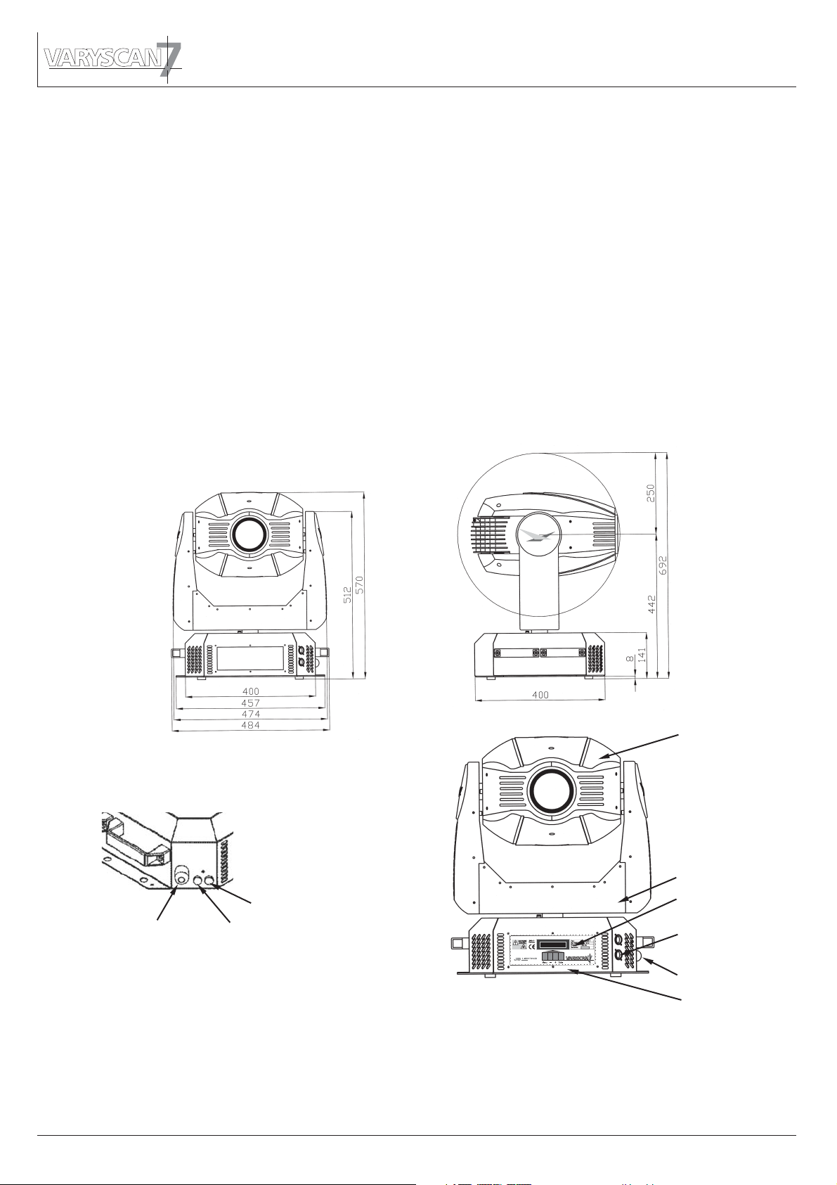
1.3 Technische Daten
7
-
Sicherung Elektronik 2 AT
Netzanschluß
Sicherung Leuchtmittel 8 AT
Gewicht: 42kg
Netzanschluß:
230V 50Hz
Stromaufnahme: 7,4A
Leuchtmittel: OSRAM HMI 1200W/S
Max.
Umgebungstemp.: 40°C
Kopf
Arm
Bedienfeld
DMX-Buchsen
Netzanschluß
Fuß
4
Page 4
2. Installation
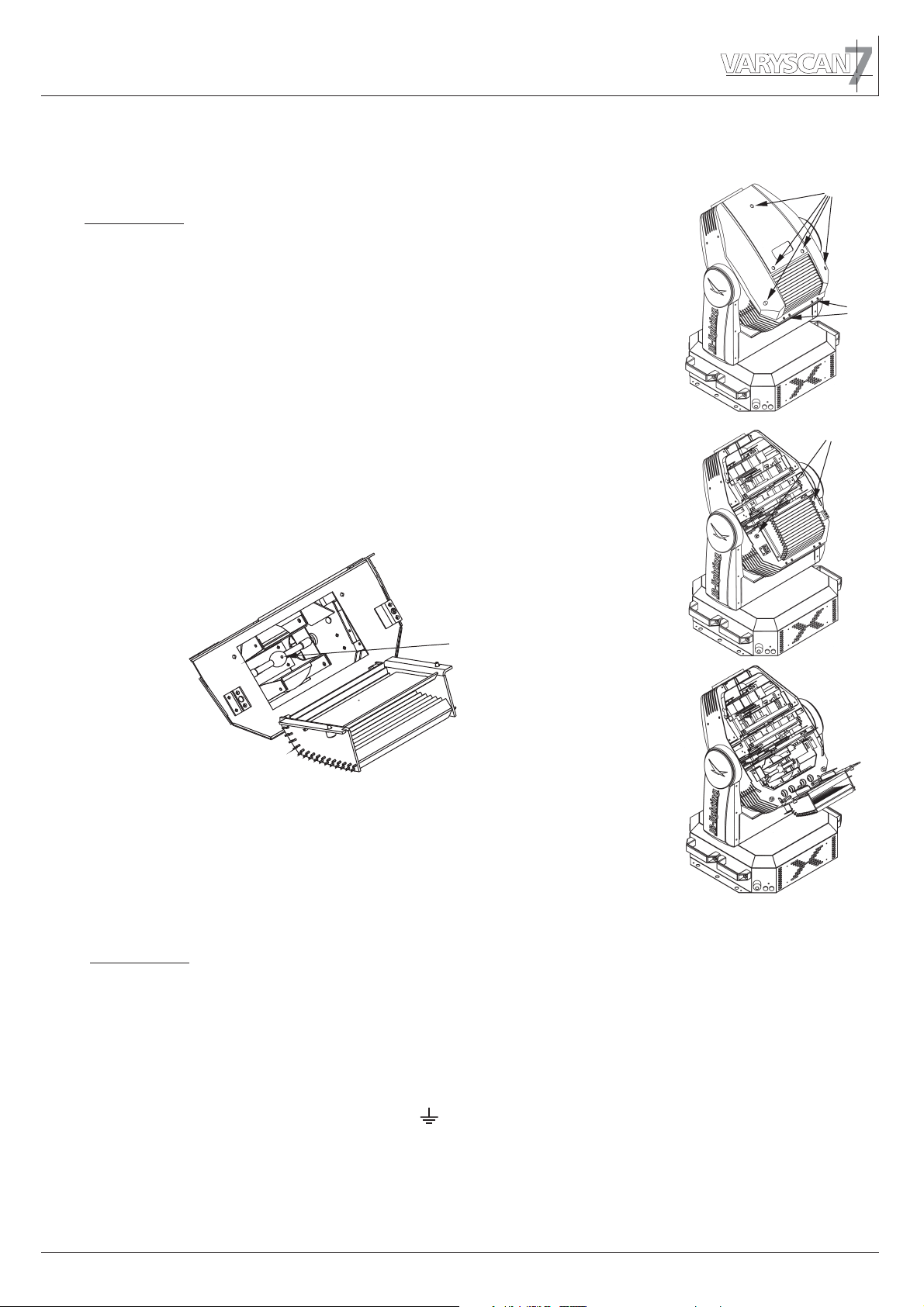
2.1 Leuchtmittel einsetzen/wechseln
ACHTUNG: Gerät vom Netz trennen und mindestens
30 Minuten abkühlen lassen !
Leuchtmittel: OSRAM HMI 1200W/S
Am Scharnier Nr.1 erkennen Sie wo oben am Kopf ist.
Drehen Sie die 5 Schrauben Nr.2 mit einer halben Umdrehung
nach links und nehmen die Kunststoffabdeckung ab.
Öffnen Sie nun die 2 Rändelschrauben Nr.3 und klappen
den Deckel nach oben.
Nun können Sie das Leuchtmittel in die Fassung einsetzen.
Achten Sie darauf, daß der Pumpstengel an dem Leuchtmittel
nach oben zeigt, siehe Skizze.
2
1
3
Pumpstengel
Beim Einsetzen der Lampe ist darauf zu achten, daß Sie
den Lampenkolben nicht mit bloßen Händen berühren.
Immer nur am Sockel (Metall) anfassen.
2.2 Netzstecker montieren
ACHTUNG: Nur von einem Fachmann durchführen lassen !
Die Montage des Schukosteckers, bzw. der Anschluss des Varyscans
an die Stromversorgung (230 Volt, 50 Hertz), muß von einem autorisierten
Fachmann durchgeführt werden.
braun Phase “L”
blau Nulleiter “N”
grün/gelb Schutzleiter
5
Page 5
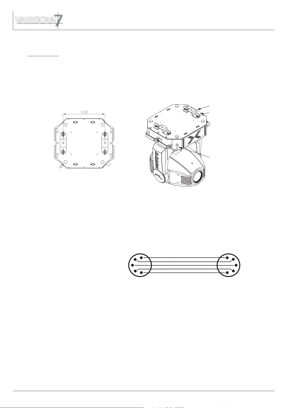
2.3 Montage der Geräte
ACHTUNG: Mindestens 2m Abstand zu brennbaren Gegenständen !
Varyscan immer mit Sicherungsseil zusätzlich sichern !
Der Varyscan 7 kann auf den Boden gestellt, oder an den dafür vorgesehenen
Camloclaschen senkrecht oder waagerecht montiert werden. Bei der Montage mit den
Camloclaschen müssen immer zwei Camlochlaschen verwendet werden und die Camlocs
müssen richtig eingerastet sein.
Varyscan zusätzlich mit Sicherungsseil an der Sicherungsöse sichern.
Camlocklasche
Camloc
Sicherungsöse
2.4 DMX Verkabelung
Die DMX Verkabelung (Signalleitungen) sollte mit einem 4-poligen Kabel mit Abschirmung
verkabelt werden. Wir empfehlen ein DMX-Kabel, es kann jedoch alternativ auch ein
2-poliges Mikro-Kabel verwendet werden.Hierbei ist jedoch kein Software-Update zu den
Varyscans möglich. Pin 4 und 5 sin dann nicht belegt.
Stecker und Buchsen sind 5-pol XLR, und können im Fachhandel erworben werden.
Steckerbelegung
Pin 1 = Ground = Abschirmung
Pin 2 = DMX Pin 3 = DMX +
3
Pin 4 = Data out Pin 5 = Data out +
Die DMX Kabel von Varyscan zu Varyscan werden eins zu eins verbunden.
Verbinden Sie nun den Ausgang Ihres Controllers mit dem 1. Varyscan. (Controller DMXOut mit Varyscan DMX-In). Anschließend den 1. Varyscan mit dem 2. Varyscan (Varyscan
1 DMX-Out mit Varyscan 2 DMX-In) und so weiter.Beim letzten Gerät bleibt die Buchse
DMX-Out unbelegt. In manchen Fällen ist es ratsam einen so genannten Endstecker
(XLR-Stecker mit einem Widerstand von 120 Ohm zwischen Pin 2 und Pin 3) einzustecken. Ob ein Endstecker benötigt wird hängt von verschiedenen Faktoren (unter anderem den benutzten Kabellängen und der Geräte Anzahl ab). Solange jedoch keine
Probleme in der DMX-Linie auftreten, kann darauf verzichtet werden.
1
2
4
Kabel mit Abschirmung
5
1
2
3
4
5
6
Page 6
2.5 Netzstrom verkabeln
Netzstecker montieren siehe Kapitel 2.2.
Anschlußwerte: Spannung 230V, Frequenz 50Hz, Leistung 1700VA (7,4A)
Es sollten jedoch mindestens 1800VA (8A) zur Verfügung gestellt werden, da das Gerät
beim Hochfahren mehr Strom benötigt.
Die elektrische Sicherheit und die Funktion des Gerätes ist nur dann gewährleistet, wenn
es an ein vorschriftsmäßig installiertes Schutzleitersystem angeschlossen wird. Es ist sehr
wichtig, daß diese grundlegende Sicherheitsvoraussetzung vorhanden ist. Lassen Sie im
Zweifelsfall die Elektroinstallation durch einen Fachmann überprüfen. Der Hersteller kann
nicht für Schäden verantwortlich gemacht werden, die durch einen fehlenden oder unterbrochenen Schutzleiter verursacht werden ! (z.B. Elektrischer Schlag).
Benutzen Sie das Gerät nur im komplett zusammengebauten Zustand, damit keine elektrischen Bauteile berührt werden können.
Wenn Sie die aufgeführten Punkte beachtet haben, können Sie die Geräte einstecken,
oder von einem Fachmann an das Netz anschließen lassen.
3. Bedienfeld
(Lebensgefahr 5000V)
1700VA
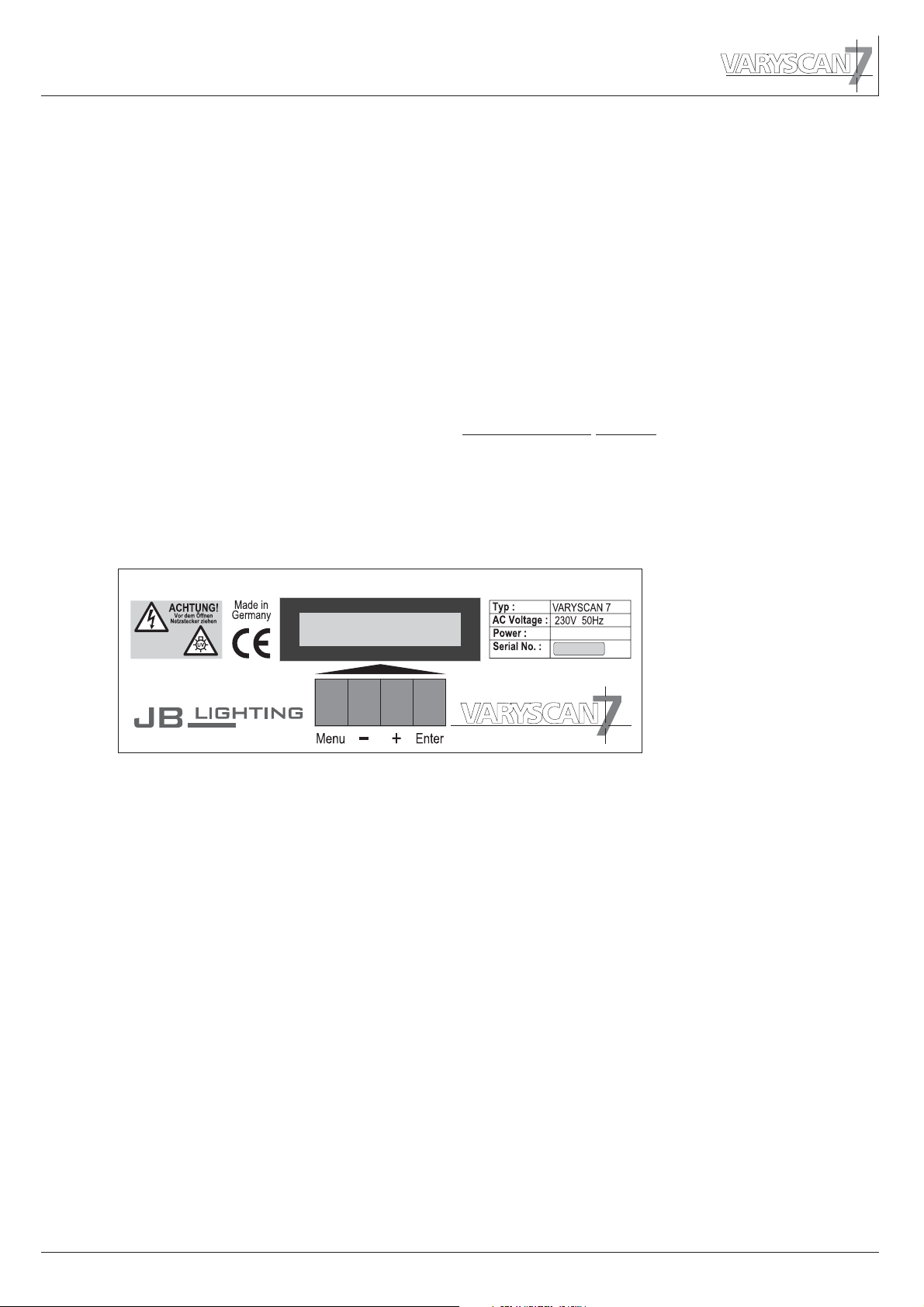
Am Bedienfeld im Fuß des Gerätes können sämtliche Parameter des Varyscan 7 eingestellt werden (siehe Menü-Übersicht nächste Seite). Durch einmaliges betätigen der
Taste "Menu" gelangen Sie in das Menü. Mit den Tasten "-" und "+" können Sie die einzelnen Menüpunkte aufrufen. Mit "Enter" gelangen Sie ins nächste Untermenü. Durch
drücken der Taste "Menu" gelangen Sie eine Stufe zurück.
Der Displaybeleuchtung werden besondere Funktionen zugeordnet:
Beim Reset des bleibt die Displaybeleuchtung ausgeschaltet.
Langsam blinkende Displaybeleuchtung bei der Anzeige bedeutet es liegt
kein DMX-Signal an. Schnell blinkende Displaybeleuchtung bei der Anzeige
bedeutet, in der "Error List" ist ein Fehler abgespeichert, der noch nicht gelöscht wurde
(Löschen siehe Seite 8 Menü Übersicht - Service).
Schnell blinkende Displaybeleuchtung bei einer Fehlermeldung im Display (z.B. *PAN
TIMEOUT) zeigt einen aktuellen Fehler an - wenden Sie sich an Ihren Händler oder
unsere Serviceabteilung.
Ist der Varyscan 7 mit einem DMX-Signal angesteuert erlischt die Beleuchtung nach 30
Sekunden.
Varyscan 7
Varyscan 7
7
Page 7
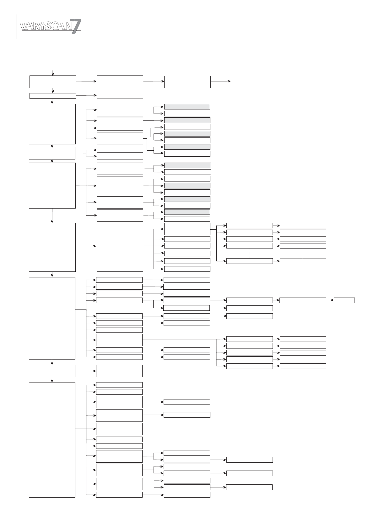
3.1 Menü-Übersicht
Taste Menu
FACTORY DEFAULT
(Werkseinstellung)
+
DMX ADRESS
Enter
LOAD DEFAULS
ADRESS +/-
Enter
SURE ?
Enter
PAN/TILT
DMX/STANDALONE
PERSONALITY
(Geräte Parameter)
STANDALONE STEPS
SERVICE
DMX-TEST
RESOLUTION
(Auflösung)
PAN INVERS
TILT INVERS
PAN/TILT SWAP
(tauschen)
DMX MODE
STANDALONE
LAMP ON/OFF DMX
LAMP MODE
SHORTEST DIST.
(Kürzester Weg)
PAN/TILT MODE
STEP NR.
+/-
RESET FIXTURE
LAMP ON
LAMP OFF
EROR LIST
FUNCTIONS TEST
INIT PAN TILT
INIT LAMP SENSE
FINE ADJUST
(Feinjustierung)
CROSSLOAD SOFT
RECEIVESOFT
DMX CHANNEL
16 BIT
8 BIT
NORMAL
INVERS
NORMAL
INVERS
NORMAL
INVERS
ON
OFF
AUTO START
AUTO OFF
AUTO DMX
ON
OFF
JB MODE
HOG MODE
MODIFY
(Bild ändern)
CAPT DMX
INSERT
DELETE
RESET STEP
CLEAR ALL
SURE ?
SURE ?
SURE ?
LIST
CLEAR
START TEST
SURE ?
SURE ?
SURE ?
FADE TIME
NEXT TIME
PAN
TILT
MOVE B-OUT
COLOR1 TIMEOUT
SURE ?
TEST RUNNING...
OFS GOBO 1
OFS GOBO 2
OFS COLOR 1
OFS COLOR 2
OFS DIMMER
FADE TIME
NEXT TIME
PAN
TILT
MOVE B-OUT
COUNT : 1
OFS GOBO 1
OFS GOBO 2
OFS COLOR 1
OFS COLOR 2
OFS DIMMER
+/+/+/+/-
+/-
CLEAR?
+/+/+/+/+/-
SOFTWARE VERSION
FIRMWARE VERSION
INFO
REM. LAMP TIME
(Lebensdauer Lampe)
LAMP STRIKES
(Betriebszähler Lampe)
TOT LAMP TIME
(Bertiebsstundenzähler)
TOT LAMP STRIKES
TOT OPERATE TIME
TEMP BASE
TEMP HEAD PCB.
TEMP HEAD LAMP
AC IN VOLTAGE
RESET ?
RESET ?
ACTUAL
MAX
ACTUAL
MAX
ACTUAL
MAX
230 V
RESET ?
RESET ?
RESET ?
8
Page 8

3.2 Parameter zurücksetzen
Um den VS 7 auf die Werkseinstellung zurück zu setzen, drücken Sie die Taste Menu.
Im Display erscheint die Meldung: Anschließend drücken Sie Taste
Enter und es erscheint . Durch erneutes Drücken der Enter Taste akti
vieren Sie die Abfrage . Durch Bestätigen über die Enter-Taste werden die Para
meter auf Werkseinstellung zurück gesetzt.
LOAD DEFAULTS -
SURE -
FACTORY DEFAULT.
3.3 DMX Adressierung
Durch drücken der Taste + oder - kann die DMX-Adresse verändert werden.
Mit der Taste Enter wird der Wert bestätigt.
3.4 Standalone-Betrieb
Im Standalone-Betrieb können Sie zuvor abgespeicherte Bilder als Endlosschleife abrufen.
Die Speicherung der Bilder kann dabei auf zwei Arten erfolgen. Entweder Sie stellen die
gewünschten DMX-Werte direkt am VS 7 ein und speichern diese ab, oder Sie stellen die
DMX-Werte über ein angeschlossenes DMX-Pult ein und speichern Sie anschließend im
VS 7 ab.
Einstellen der DMX-Werte am Gerät
Rufen Sie den Standalone-Betrieb folgendermaßen auf:
Drücken Sie zuerst die Taste Menu und anschließend fünf Mal auf die Taste + (siehe Seite
8). Im Display sehen Sie die Meldung: Bestätigen Sie die Meldung
durch drücken der Taste Enter.
Nun steht im Display die Meldung: die wiederum mit Enter bestätigt
werden muß. Nach der Bestätigung steht die Meldung: im Display. Rufen Sie
das Modify Menü durch Drücken der Enter Taste auf.
Nun haben Sie Zugriff auf sämtliche Parameter des VS 7. Drücken Sie so oft die Taste +,
bis das gewünschte Scheinwerferparameter im Display dargestellt wird, z.B. .
Nun bestätigen Sie die Auswahl mit Enter und geben dann über die Tasten + und - den
gewünschten DMX Wert ein.
Die Abspeicherung der DMX-Werten bestätigen Sie einfach durch Drücken der Taste Enter.
Verlassen Sie das Menü durch Drücken der Taste Menu.
Anhängen eines weiteren Schrittes:
Drücken Sie so oft auf die Taste +, bis Sie im Menü-Punkt: sind.
Drücken Sie dann einmal auf die Taste Enter; im Display erscheint die Abfrage:
Bestätigen Sie nun mit der Taste Enter, es wird ein neuer Schritt angehängt.
Die DMX-Werte des vorigen Schritts werden in den neuen Schritt kopiert. Zum Ändern der
DMX-Werte rufen Sie das Modify-Menü auf und verfahren wie oben beschrieben.
Löschen eines Schrittes:
Rufen Sie das Standalone Menü auf. Im Display muss folgende Meldung stehen:
STANDALONE STEPS.
Im Display steht nun folgende Meldung:
Mit der Taste + können Sie nun den gewünschten Schritt aufrufen. Sobald Sie ihn aktiviert
haben drücken Sie die Taste Enter und wählen dann über die Taste + den Menü-Punkt
DELETE
Sicherheitsabfrage: Diese Sicherheitsabfrage müssen Sie durch erneutes Drücken
der Taste Enter bestätigen, dann ist der Schritt gelöscht.
an. Zum Löschen des Schrittes drücken Sie nun die Taste Enter. Es erfolgt die
.
STANDALONE STEPS.
STEP NR. 1/1,
MODIFY 1/1
PAN
INSERT
SURE?
Nun bestätigen Sie durch Drücken der Taste Enter.
STEP NR: 1 / X
SURE?
9
Page 9

Zurücksetzen der DMX-Werte in einem Schritt:
Sollten Sie die DMX-Werte eine Schrittes zurücksetzen wollen, dann gehen Sie
folgendermaßen vor:
Drücken Sie zuerst die Taste Menu und anschließend fünf Mal auf die Taste +
Im Display sehen Sie die Meldung:
Bestätigen Sie die Meldung durch Drücken der Taste Enter.
Nun steht im Display die Meldung: Rufen Sie durch Drücken der Taste +
den gewünschten Schritt auf und bestätigen Sie mit Enter.
Nun können Sie über die Taste + den Menü-Punkt aufrufen.
Wenn Sie den Menü-Punkt aufgerufen und durch Drücken der Taste Enter bestätigt haben,
erscheint im Display die Sicherheitsabfrage:
Durch erneutes Drücken der Taste Enter bestätigen Sie Ihre Auswahl und die DMX-Werte
des angewählten Schrittes werden auf den Ursprungswert zurückgesetzt.
Übernehmen der DMX-Werte von einem externen Pult:
Rufen Sie das Standalone Programmier-Menü folgendermaßen auf:
Drücken Sie zuerst die Taste Menu und anschließend fünf Mal die Taste +. Im Display
erscheint die Meldung: . Bestätigen Sie die Auswahl durch Drücken
der Taste Enter und drücken Sie anschließend ein Mal die Taste +
Im Display steht folgende Meldung: Drücken Sie jetzt auf die Taste Enter
um den DMX-Eingang freizuschalten. Im Display erscheint die Meldung:
und der VS 7 reagiert auf die eingestellten DMX-Werte.
Zum Übernehmen drücken Sie die Taste Enter. Im Display steht dann die Meldung:
CAPT DMX 1/1.
Dazu drücken Sie ein Mal auf die Taste +. Im Display steht:
Drücken Sie nun die Taste Enter; es erfolgt die Sicherheitsabfrage:
Bestätigen Sie ein weiteres Mal durch Drücken der Taste Enter und im Display wird die
Bestätigung sichtbar:
Um mit dem Programmieren fortzufahren, drücken Sie nun ein Mal die Taste - .
Das Display wird folgende Meldung zeigen:
Schalten Sie den DMX-Eingang frei indem Sie erneut auf die Taste Enter drücken.
Das Display wird wiederum: zeigen.
Wiederholen Sie den oben aufgeführten Vorgang.
Anschließend hängen Sie einen Schritt an. .
STANDALONE STEPS
INSERT 2/2
DMX CAPTURE
STANDALONE STEPS
STEP NR. 1/X.
RESET STEP
SURE?
CAPT DMX 1/ 1.
DMX CAPTURE
INSERT 1/1
SURE?
CAPT DMX 2/2
10
Um die am Pult eingestellten Werte zu übernehmen drücken Sie jetzt zwei Mal die Taste
Enter. (Nach dem ersten Drücken steht im Display: ; nach dem zweiten
Drücken:
Nun fügen Sie einen weiteren Schritt wie in Kapitel:
ein und wiederholen diese Vorgänge.
CAPT DMX X / X)
START CAPTURE
Anhängen eines weiteren Schrittes
Page 10

Aktivieren des Standalone Betriebs:
Unabhängig davon ob die DMX-Werte der einzelnen Schritte manuell eingegeben oder
von einem Pult übernommen wurden, wird der Standalone-Betrieb im Menü
DMX/STANDALONE eingestellt.
Um das Menü aufzurufen drücken Sie zuerst die Taste Menu und anschließend drei Mal
die Taste +. Im Display steht dann:
Diese Meldung bestätigen Sie durch Drücken der Taste Enter.
Nun können Sie über die Taste + die Standalone-Funktion anwählen und durch einmaliges
Drücken der Taste Enter.aktivieren.
Im Display steht folgende Bestätigung:
Deaktivieren des Standalone Betriebs:
Um den Standalone-Betrieb zu deaktivieren drücken Sie die Taste Enter.
Anschließend drücken Sie die Taste - und im Display wird folgende Meldung angezeigt:
DMX MODE
Drücken Sie nochmals die Taste Enter. Im Display steht dann:
Verlassen Sie das Menü durch Drücken der Taste Menu.
DMX/STANDALONE.
S-ALONE: 1 / 2
DMX/STANDALONE.
3.5 Leuchtmittel-Steuerung
Beim VS 7 stehen folgende Möglichkeiten zur Leuchtmittel-Steuerung zur Verfügung:
Einstellungen zur werden in der Personality Konfiguration im
Menü-Punkt eingestellt
Möglichkeit 1: Das Leuchtmittel zündet, sobald Strom fließt
Möglichkeit 2: Das Leuchtmittel zündet, sobald Strom fließt und auf dem Lamp on/off
Möglichkeit 3: Das Leuchtmittel zündet, sobald Strom fließt und ein DMX-Signal
Einstellung zur
Unabhängig von den Einstellungen zur Leuchtmittel-Zündung funktioniert die
Leuchtmittel-Steuerung über DMX. Damit das Leuchtmittel über DMX angesprochen
werden kann, muss dies in der Personality Konfiguration unter dem Memü-Punkt
LAMP ON/OFF DMX
Wenn im Personality Menü-Punkt der Menüpunkt eingestellt
wurde zündet der VS 7 das Leuchtmittel wie oben beschrieben, es kann aber nur bei
Möglichkeit 2 auch wieder ausgeschaltet werden.
Wenn im Personality Menü-Punkt der Menüpunkt eingestellt
wurde, zündet der VS 7 das Leuchtmittel wie oben beschrieben, es kann aber immer über
DMX wieder ausgeschaltet werden. (Kanal Nr. 5 DMX-Wert von 232-239 länger als 3
Sekunden).
Leuchtmittel-Zündung
LAMP MODE
(AUTO START)
Kanal Nr. 5 ein DMX-Wert von 248 - 255 angewählt wird
anliegt
Leuchtmittel-Steuerung:
(AUTO DMX)
zuerst eingestellt werden.
LAMP ON/OFF DMX
LAMP ON/OFF DMX
(AUTO OFF)
OFF
ON
11
Page 11

4. Kanalbelegung
JB MODE
Kanal 1 Pan
Kanal 2 Tilt
Kanal 3 Pan fein
Kanal 4 Tilt fein
HOG MODE
Kanal 1 Pan
Kanal 2 Pan fein
Kanal 3 Tilt
Kanal 4 Tilt fein
Aufteilung der einzelnen Kanäle
JB MODE
Kanal 1 Pan (X) Bewegung
Kanal 2 Tilt (Y) Bewegung
Kanal 3 Pan (X) fein
Kanal 4 Tilt (Y) fein
Kanal 5 Sicherheit
Lampe aus (nach 3 Sekunden)
Reset (nach 1 Sekunde)
Lampe an
Kanal 6 Shutter zu
Shutter auf
Stroboskop-Effekt (langsam ->schnell)
Shutter auf
Shutter zu
Shutter pulsierend öffnen (schnell -> langsam)
Shutter auf
Shutter
Shutter zu
Shutter fade 0% (langsam 4,8sec-schnell 0,6sec)
Shutter auf
Shutter fade 100% (langsam 4,8sec-schnell 0,6sec)
Shutter zu
Shutter Zufall 100% (langsam 4,8sec-schnell 0,6sec)
Shutter auf
Shutter Zufall 0% (langsam 4,8sec-schnell 0,6sec)
Shutter zu
S. Zufall fade 0% (langsam 4,8sec-schnell 0,6sec)
Shutter auf
S. Zufall fade 100% (langsam 4,8sec-schnell 0,6sec)
Shutter auf
Kanal 7
Kanal 8 Iris 0-100%
Dimmer 0-100%
Iris zu
Iris Shuttereffekt länger auf
Iris auf
Iris Shuttereffekt länger zu
Iris zu
pulsierend schließen (schnell -> langsam)
Kanal 5 Lampe, Reset
Kanal 6 Shutter
Kanal 7 Dimmer
Kanal 8 Iris
Kanal 9 Fokus
Kanal 10 Goborad 1
Kanal 11 Goborotation 1
Kanal 12 Goborad 2
Kanal 13 Goborotation 2
Kanal 14 Farbrad
HOG MODE
Kanal 1 Pan (X) Bewegung
Kanal 2 Pan (X) fein
Kanal 3 Tilt (Y) Bewegung
Kanal 4 Tilt (Y) fein
Kanal 15 Farbeffektrad
Kanal 16 Nicht belegt
Kanal 17 Prisma
Kanal 18 Prismarotation
Kanal 19 Frostfilter
Kanal 20 Pan / Tilt Geschw.
Kanal 21 Effektgeschwindigkeit
Kanal 22 Black Out Modus
DMX 000-255
DMX 000-255
DMX 000-255
DMX 000-255
DMX 000-231
DMX 232-239
DMX 240-247
DMX 248-255
DMX 000-015
DMX 016-111
DMX 112-125
DMX 126
DMX 127
DMX 128-142
DMX 143
DMX 144-158
DMX 159
DMX 160-174
DMX 175
DMX 176-190
DMX 191
DMX 192-206
DMX 207
DMX 208-222
DMX 223
DMX 224-238
DMX 239
DMX 240-254
DMX 255
DMX 000-255
DMX 000-126
DMX 127
DMX 128-142
DMX 143
DMX 144-158
DMX 159
00-FF
00-FF
00-FF
00-FF
00-0F
E8-EF
F0-F7
F8-FF
00-0F
10-6F
70-7D
7E
7F
80-8E
8F
90-9E
9F
A0-AE
AF
B0-BE
BF
C0-CE
CF
D0-DE
DF
E0-EE
EF
F0-FE
FF
00-FF
00-7E
7F
80-8E
8F
90-9E
9F
12
Page 12

Iris fade zu
Iris auf
Iris fade auf (langsam 4,8sec-schnell0,6sec)
Iris zu
Iris Zufall öffnend (langsam 4,8sec-schnell 0,6sec)
Iris auf
Iris Zufall schließend(langsam 4,8sec-schnell 0,6sec)
Iris zu
Iris Zufall fade zu (langsam 4,8sec-schnell 0,6sec)
Iris auf
Iris Zufall fade auf (langsam 4,8sec-schnell 0,6sec)
Iris auf
Kanal 9
Kanal 10 Goborad 1 Durchgang
Kanal 11 Gobopositionierung
Kanal 12
Kanal 13 Gobopositionierung
Kanal 14 Farbe 1 weiß
Fokus 0-100%
Gobo 1
Gobo 2
Gobo 3
Gobo 4
Goborad 1 Durchgang Swing
Gobo 1 Swing
Gobo 2 Swing
Gobo 3 Swing
Gobo 4 Swing
Goboraddreh rechts (schnell - langsam)
Goboraddreh links
Goborotation rechts
Goborotation Stop
Goborotation links
Goborad 2 Durchgang
Gobo 1
Gobo 2
Gobo 3
Gobo 4
Goborad 2 Durchgang Swing
Gobo 1 Swing
Gobo 2 Swing
Gobo 3 Swing
Gobo 4 Swing
Goboraddreh rechts (schnell - langsam)
Goboraddreh links
Goborotation rechts
Goborotation Stop
Goborotation links
Farbe 2 weiß/rot
Farbe 3 rot
Farbe 4 rot/gelb
Farbe 5 gelb
Farbe 6 gelb/magenta
Farbe 7 magenta
Farbe 8 magenta/grün
(langsam 4,8sec-schnell 0,6sec)
(langsam - schnell)
(langsam - schnell)
DMX 160-174
DMX 175
DMX 176-190
DMX 191
DMX 192-206
DMX 207
DMX 208-222
DMX 223
DMX 224-238
DMX 239
DMX 240-254
DMX 255
DMX 000-255
DMX 000-015
DMX 016-031
DMX 032-047
DMX 048-063
DMX 064-079
DMX 128-135
DMX 136-143
DMX 144-151
DMX 152-159
DMX 160-167
DMX 192-223
DMX 224-255
DMX 000-191
DMX 192-222
DMX 223-224
DMX 225-255
DMX 000-015
DMX 016-031
DMX 032-047
DMX 048-063
DMX 064-079
DMX 128-135
DMX 136-143
DMX 144-151
DMX 152-159
DMX 160-167
DMX 192-223
DMX 224-255
DMX 000-191
DMX 192-222
DMX 223-224
DMX 225-255
DMX 000-003
DMX 004-007
DMX 008-011
DMX 012-015
DMX 016-019
DMX 020-023
DMX 024-027
DMX 028-031
A0-AE
AF
B0-BE
BF
C0-CE
CF
D0-DE
DF
E0-EE
EF
F0-FE
FF
00-FF
00-0F
10-1F
20-2F
30-3F
40-4F
80-87
88-8F
90-97
98-9F
A0-A7
C0-DF
E0-FF
00-BF
C0-DE
DF-E0
E1-FF
00-0F
10-1F
20-2F
30-3F
40-4F
80-87
88-8F
90-97
98-9F
A0-A7
C0-DF
E0-FF
00-BF
C0-DE
DF-E0
E1-FF
00-03
04-07
08-0B
0C-0F
10-13
14-17
18-1B
1C-1F
13
Page 13

Farbe 9 grün
Farbe 10 grün/orange
Farbe 11 orange
Farbe 12 orange/blau
Farbe 13 blau
Farbe 14 blau/türkis
Farbe 15 türkis
Farbe 16 türkis/weiß
Farben stufenlos positionieren
Farbraddreh rechts
Farbraddreh Stop
Farbraddreh links
Kanal 15 Durchgang
CTB Tageslichtfilter
CTO Kunstlichtfilter
Vierfarbfilter
UV-Filter
Pink
Cyan
Kombinierter Modus zur Farbsteuerung mit Farbrad
Kanal 16 nicht belegt
Kanal 17 Prisma ausgeklappt
Prisma eingeklappt
Prisma Swing
Kanal 18 Prismapositionierung
Prismarotation rechts (langsam-schnell)
Prismarotation Stop
Prismarotation links (langsam-schnell)
Kanal 19 Frost 0-100%
Frost 100%
Shuttereffekt länger Frost 100% (schnell-langsam)
Frost 0%
Shuttereffekt länger Frost 0% (schnell-langsam)
Frost 100%
Frost fade in (langsam-schnell)
Frost 0%
Frost fade out (langsam-schnell)
Frost 100%
Frost Zufall öffnend (langsam-schnell)
Frost 0%
Frost Zufall schließend (langsam-schnell)
Frost 100%
Frost Zufall fade in (langsam-schnell)
Frost 0%
Frost Zufall fade out (langsam-schnell)
Frost 100%
Kanal 20 Bewegung in Echtzeit
Bewegung Zeit verzögert (langsam-schnell)
Kanal 21 Effekte in Echtzeit
Effekte Zeit verzögert (langsam-schnell)
DMX 032-035
DMX 036-039
DMX 040-043
DMX 044-047
DMX 048-051
DMX 052-055
DMX 056-059
DMX 060-063
DMX 064-191
DMX 192-222
DMX 223-224
DMX 225-255
DMX 000-015
DMX 016-031
DMX 032-047
DMX 048-063
DMX 064-079
DMX 080-095
DMX 096-111
DMX 128-255
DMX 000-015
DMX 016-031
DMX 128-135
DMX 000-191
DMX 192-222
DMX 223-224
DMX 225-255
DMX 000-126
DMX 127
DMX 128-142
DMX 143
DMX 144-158
DMX 159
DMX 160-174
DMX 175
DMX 176-190
DMX 191
DMX 192-206
DMX 207
DMX 208-222
DMX 223
DMX 224-238
DMX 239
DMX 240-254
DMX 255
DMX 000-003
DMX 004-255
DMX 000-003
DMX 004-255
20-23
24-27
28-2B
2C-2F
30-33
34-37
38-3B
3C-3F
40-BF
C0-DE
DF-E0
E1-FF
00-0F
10-1F
20-2F
30-3F
40-4F
50-5F
60-6F
80-FF
00-0F
10-7F
80-87
00-BF
C0-DE
DF-E0
E1-FF
00-7E
7F
80-8E
8F
90-9E
9F
A0-AE
AF
B0-BE
BF
C0-CE
CF
D0-DE
DF
E0-EE
EF
F0-FE
FF
00-03
04-FF
00-03
04-FF
14
Page 14

Kanal 22 Keine Funktion
Dimmer schließt bei Pan-Tilt
Dimmer schließt bei Gobo,Farbe,Prisma
Dimmer schließt bei Gobo, Farbe,Prisma, Fokus
Dimmer schließt bei Gobo, Farbe, Prisma,Pan-Tilt
Dimmer schließt bei Gobo,Farbe,Prisma,Fok.,Pan-Tilt
Die Fadezeit beim Dimmer ist einstellbar von langsam 5sec-max
5. Service
5.1 Gobos wechseln
ACHTUNG: Gerät vom Netz trennen und mindestens
30 Minuten abkühlen lassen !
Am Scharnier Nr.1 erkennen Sie wo oben am Kopf ist.
Drehen Sie die 5 Schrauben Nr.2 mit einer halben Umdrehung
nach links und nehmen die Kunststoffabdeckung ab.
Öffnen Sie nun die 2 Rändelschrauben Nr.3 und ziehen den
Goboeinschub heraus.
Standardbestückung
DMX 000-095
DMX 096-127
DMX 128-159
DMX 160-191
DMX 192-223
DMX 224-255
00-50
60-7F
80-9F
A0-BF
C0-DF
C0-EF
2
1
Die Gobos sind mit einer Feder in das Gobozahnrad gespannt.
Zum Wechseln lösen Sie diese und befestigen Sie dann das
neue Gobo. Beim einsetzen von Metallgobos ist darauf zu
achten, daß die schwarze lackierte Seite Richtung Objektiv
zeigt und nicht Richtung Leuchtmittel. Ebenso bei Glasgobos
muß die beschichtete Seite Richtung Objektiv zeigen.
Bei Gobos die sich nicht verdrehen dürfen z.B. Logos,
empfehlen wir das zusätzliche sichern von dem Gobo
mit einem Tropfen Silikon.
3
Wenn Sie eigene Gobos herstellen lassen wollen,
beachten Sie bitte folgende Zeichnung.
Nutzdurchmesser: (Platz für Ihr Motiv) 48mm
Außendurchmesser: 51,8mm (+0/-0,2mm)
48mm
51,8mm
15
Page 15

5.2 Leuchmittel wechseln
Siehe Kapitel 2.2
5.3 Gerät reinigen
ACHTUNG: Gerät vom Netz trennen und mindestens 30 Minuten abkühlen lassen !
Sie sollten in regelmäßigen Abständen die Funktion der Lüfter im Kopf und Fuß überprüfen.
Vor allem sollten Sie darauf achten, daß die Lufteinlässe und das Innere des Varyscan frei
von Fusseln und Staub sind.
Hierzu öffnen Sie die beiden Deckel am Kopf und die Bodenplatte am Fuß.
Nun können Sie den Varyscan mit einem Pinsel und einem Staubsauger säubern.
Achten Sie darauf, daß Sie beim Reinigen keine Teile verbiegen oder beschädigen.
Bei Schäden, die auf unsachgemäße Handhabung zurückzuführen sind, erlischt
die Garantie!
5.4 Optik reinigen
ACHTUNG: Gerät vom Netz trennen und mindestens 30 Minuten abkühlen lassen !
Sie sollten in regelmäßigen Abständen die optischen Teile reinigen, um wieder die
maximale Helligkeit und die maximale Abbildungsqualität zu erreichen.
Hierzu öffnen Sie die beiden Deckel am Kopf und reinigen den Reflektor, die Linsen und
die Farbfilter mit einem fusselfreien Tuch und etwas Fensterputzmittel. Sie können
auch Q-Tips oder eine Pinzette zu Hilfe nehmen.
Beim Reinigen des Reflektors und der Kondensorlinse sollten Sie das Leuchtmittel
vorher entfernen, damit es nicht beschädigt wird.
5.5 Drehbare Gobos ölen
ACHTUNG: Gerät vom Netz trennen und mindestens 30 Minuten abkühlen lassen !
Die drehbaren Gobos sollten 1-2mal im Jahr mit JB-Spezialöl geölt werden.
Bitte verwenden Sie kein anderes Öl, es würde wegen der großen Hitze
verharzen und verklumpen.
Drehen Sie die Zahnräder mit der Hand und geben ca. 4-6 Tropfen von dem
Öl in die Kugeln von den Gobozahnrädern.
5.6 Software updaten
Der Varyscan 7 lässt sich über einen PC/notebook mit Hilfe eines Upgrade-Dongles
(USB/DMX Converter) über den 5 poligen DMX Eingang updaten. Den Upgrade Dongle
mit der dazugehörigen Software erhalten Sie bei unseren Stützpunkt-Händlern.
16
Page 16

5.7 Stromlaufplan
Zünder
ZRM (D)
Trafo
Fan2
230 V
ZRM (D)
230 V
240 V
Drossel 2
Drossel 1
Lüfter
+32 V
+32 V
GND
GND
N
LA
D
220 V
240 V
220 V
Kondensator 1
Main PCB
24V~
I-LockI-Lock
Shutter
Shutter
Kondensator 2
24V AC
16A 250V~
Shutter
Shutter
Motor
Motor
Motor
Motor
62.22.8.024.4300
Finder
N IN
HOT IN
Flood
Flood
N OUT
HOT OUTHOT OUT
Motor
Motor
COMP C2COMP C2
OM
C
COMP C1
Flood
Flood
Sicherung
1
C
P
Motor
Motor
2AT
Elektronik
8AT
Leuchtmittel
Sicherung
N
Netzfilter
N
L
L
Farbrad1
Farbrad1
Motor
Motor
Rückansicht der Kopfplatine
Gelb
Schwarz
Rot
Head 4
Head 3
Gelb
P-Rot
P-Rot
Gelb
Motor
Motor
+5V
+32V
GND
+15V
Gelb
Weiß
Grau
Grün
Gelb
Braun
Blau
Grün
Gelb
Braun
Farbrad2
Farbrad2
Motor
Motor
Grau
Grün
Blau
Head 2
Braun
Weiß
Grün
Gelb
Head 1
Braun
Rot
Blau
Schwarz
Rot
Prisma
Prisma
Motor
Motor
Weiß
Gelb
Schwarz
Rot
Weiß
Rot dünn
Rot dick
Schwarz
Gelb
Focus
Focus
Motor
Motor
+15 V
+5 V
Mot PanMot Pan
Inc Pan
Lamp Rel
Mot TitMot Tit
Fußplatine
Inc Tilt
Head4
Head3
Head2
Head1
Fan1
DMX
Diese Anschlüsse befinden
Diese Anschlüsse befinden
sich auf der Rückseite
sich auf der Rückseite
+5V
+32V
GND
+15V
HEAD4
HEAD3
HEAD2
HEAD1
Lüfter
+5V
+32V
GND
+15V
Iris
Shutter Motoren
Gobo 2
Head 2
Head 4Head 4
Head 1
Head 3
Iris
Lüfter
Flood Motoren
Prisma
Lüfter
Leer
P-Rot
Jp1
Kopfplatine
Iris
Iris
Motor
Motor
Lüfter
Lüfter
Flood
Focus
Shutter
Farbrad 2
Farbrad 1
G-Rot 1
Gobo 1
G-Rot 2
Temperaturfühler 2
2 Weis
3 Rot
1 Schwarz1 Schwarz
4 Braun
5 Gelb
Lüfter
Encoder
Encoder
Platine
Platine
Temperaturfühler 1
Tilt
Tilt
Motor
Motor
Encoder
Encoder
Platine
Platine
Pan
Pan
Motor
Motor
Endschalter Iris
Deckelschalter
Goborot 2
Goborot 2
Motor
Motor
Goborad 2
Goborad 2
Motor
Motor
Goborot 1
Goborot 1
Motor
Motor
Goborad1
Goborad1
Motor
Motor
17
Page 17

Konformitätserklärung
im Sinne der Richtlinie 89/336/EWG
der Mitgliedsstaaten über die elektromagnetische Verträglichkeit)
Der Hersteller
JB-lighting Lichtanlagentechnik GmbH
Sallersteig 15
89134 Blaustein-Wippingen
erklärt, dass das Produkt
Varyscan 7
den wesentlichen Schutzanforderungen der Richtlinie entspricht.
Es wurden folgende Normen zur Konformitätsbewertung herangezogen:
DIN EN 61000-6-2 Elektromagnetische Verträglichkeit (EMV)
Teil 6-2: Fachgrundnorm – Störfestigkeit Industriebereich
DIN EN 61000-6-4 Elektromagnetische Verträglichkeit (EMV)
Teil 6-4: Fachgrundnormen Störaussendung für den Industriebereich
DIN EN 61000-3-2 Prüfung von Oberschwingungsströme
DIN EN 61000-3-3 Prüfung von Spannungsschwankungen
Blaustein, den 03.03.2008
_______________________
Jürgen Braungardt
Geschäftsführer
6.
18
Page 18

English
19
Page 19

1. Indroduction
1.1 General Remarks
The Varyscan 7 1200HMI is equipped with 7 colours plus white, one colour effect wheel
2 x 4 gobos (rotating, indexable and interchangable),iris diaphram, focus, one rotating,
indexable and exchangeable prism, dimmer, shutter and one progressive frost filter.
The pan and tilt movement can opperate in 8bit or 16bit mode, depening on the lighting
control desk in use.
1.2 Unpacking
Open the top of the box and remove the unit with the inlays. Remove the inlays from the
Varyscan7 head and base and take the unit from the box. For any damage occuring during
transport, report to the transport company immediately.
1.3 Technical data
electronic fuse 2 Amp slow
Mains connection
lamp fuse 8 Amp slow
weight: 42Kg
Power connection:
230V 50Hz
Power consumtion: 7,4A
light source: OSRAM HMI 1200W/S
max.
ambient temperature:
40°C
head
arm
control panel
DMX connectors
mains connection
base
20
Page 20

2. Installation
2.1 Installing or changing the lamp
WARNING: Disconnect fixture from mains, and allow
hot lamp to cool down for at least 30 minutes!
Light source: OSRAM HMI 1200W/S
Position head in horizontal position. Hinge no. 1 must be on the
upper side of the head. Turn screws no. 5 1/2 turn left and remove
plastic lid.
Loosen knurled head screw no. 3 and open the lampcover
2
1
Insert the lamp into the lamp holder. The nipple of the lamp
.
must face the top lid of the head. (See sketch).
Nipple
If changing the lamp, remove old lamp from
lamp socket. Hold the new lamp only by its
ceramic base. Never touch the glass bulb.
3
2.2 Powering the fixture
WARNING: To ensure propper installation of the plug consult a qualified
technician!
Install a 3-prong gounding type plug that fits your supply
Connected load: voltage 230V, frequency 50Hz, Power 1700 VA
brown live “L”
blue neutral “N”
yellow/green gound
21
Page 21

2.3 Rigging the fixture
WARNING: Keep fixtures at least 2 m away from inflamable articles!
Always use a safety cable attached to the base!
The Varyscan7 can either be placed on the floor or hung on a trussing system in a vertical
or horizontal way. If mounting the unit to walls in a vertical way, the lamplife might be
reduced. To mount the unit on a trussing system use the original JB-lighting omega brackets
with Camloc-connectors. The Camlocs must snap in to be locked propperly. Alway attach a
safety cable to secure the unit.
Omega bracket
Camloc
ringeye for safety cable
2.4 DMX wiring
Use a shielded twisted-pair cable with two pairs to connect the serial link.
For short distances a microphone cable may be used. If a microphone cable is used
the software can not be updated via DMX line for pin 4 and 5 are not connected.
Use 5-pin XLR connectors.
Pin assignment
Pin 1 = shield
Pin 2 = data Pin 3 = data +
3
Pin 4 = data out Pin 5 = data out +
The pin assignment is the same for all Varyscans in line.
If the output socket of the control desks offers a 5 pin XLR female socket,
pin 4 and 5 are not occupied.
Connect the DMX-out of the control desk to the first Varyscan in line.
(lighting control desk DMX-Out / Varyscan DMX-In). Connect the second Varyscan
to the first in line, and so on (Varyscan 2 DMX-In / Varyscan 1 DMX-Out).
The DMX-Out of the last unit in line is not occupied unless problems occure. Then
use a termition plug with the last Varyscan in line.(XLR-connector with a 120 Ohm resistor
soldered between pin 2 and pin 3). Problems might occure when the line is overloaded, e.g.
1
2
4
shielded signal cable
5
1
2
3
4
5
22
Page 22

2.5 Installing a plug on the power cord
Install a plug like described in chapter 2.2.
Connected load: Voltage 230Volts, frequence 50Hz, power 1700 VA (7,4Amps)
Use a power supply of at least 1800VA (8Amps) per unit, as the fixture need more power
during the process of powering up.
Connect the fixture to a propper installed grounded system only. If any doubts on the
electrical installations occur, consult a qualified electrician.
In case of damages occuring due to a not propper installed electrical system, warranty
claims will be invalidated.
Don´t use fixtures when top cover is not fixed propperly. Contact with electronical parts
can result in risk for life.
Connect fixture only after assuring that the electrical installation fits your demands. If any
doubts occur consult a qualified technican!
(Electrical shock 5000V)
3. Control panel
1700VA
To adjust the personal setting of the VS7 use keys located on the control panel. Functions
see menu on the following page. To enter the menu press "Menu" key one time. Use keys
"-" and "+" to move within the menu. Use key "Enter" to select the function and to recall the
next menu section. To escape press key "Menu".
Special functions are assigned to the display lighting:
During reset the display is not illuminated. Slow flashing of the display illumination means
no DMX signal is connected. Fast flashing of the display illumination showing
means a failure was reported and stored in the ERROR LIST (To clear - see menu
navigation on page 8).
Fast flashing of the display illumination showing an error message means an current
failure is reported, e. g. - please contact your dealer or our service
department. If the Vs7 is connected with a DMX-signal the display illumination shut off
after 30 seconds.
*PAN TIMEOUT
Varyscan 7
23
Page 23

3.1 Menu navigation
Taste Menu
FACTORY DEFAULT
(Werkseinstellung)
+
DMX ADRESS
Enter
LOAD DEFAULS
ADRESS +/-
Enter
SURE ?
Enter
PAN/TILT
DMX/STANDALONE
PERSONALITY
(Geräte Parameter)
STANDALONE STEPS
SERVICE
DMX-TEST
RESOLUTION
(Auflösung)
PAN INVERS
TILT INVERS
PAN/TILT SWAP
(tauschen)
DMX MODE
STANDALONE
LAMP ON/OFF DMX
LAMP MODE
SHORTEST DIST.
(Kürzester Weg)
PAN/TILT MODE
STEP NR.
+/-
RESET FIXTURE
LAMP ON
LAMP OFF
EROR LIST
FUNCTIONS TEST
INIT PAN TILT
INIT LAMP SENSE
FINE ADJUST
(Feinjustierung)
CROSSLOAD SOFT
RECEIVESOFT
DMX CHANNEL
16 BIT
8 BIT
NORMAL
INVERS
NORMAL
INVERS
NORMAL
INVERS
ON
OFF
AUTO START
AUTO OFF
AUTO DMX
ON
OFF
JB MODE
HOG MODE
MODIFY
(Bild ändern)
CAPT DMX
INSERT
DELETE
RESET STEP
CLEAR ALL
SURE ?
SURE ?
SURE ?
LIST
CLEAR
START TEST
SURE ?
SURE ?
SURE ?
FADE TIME
NEXT TIME
PAN
TILT
MOVE B-OUT
COLOR1 TIMEOUT
SURE ?
TEST RUNNING...
OFS GOBO 1
OFS GOBO 2
OFS COLOR 1
OFS COLOR 2
OFS DIMMER
FADE TIME
NEXT TIME
PAN
TILT
MOVE B-OUT
COUNT : 1
OFS GOBO 1
OFS GOBO 2
OFS COLOR 1
OFS COLOR 2
OFS DIMMER
+/+/+/+/-
+/-
CLEAR?
+/+/+/+/+/-
24
INFO
SOFTWARE VERSION
FIRMWARE VERSION
REM. LAMP TIME
(Lebensdauer Lampe)
LAMP STRIKES
(Betriebszähler Lampe)
TOT LAMP TIME
(Bertiebsstundenzähler)
TOT LAMP STRIKES
TOT OPERATE TIME
TEMP BASE
TEMP HEAD PCB.
TEMP HEAD LAMP
AC IN VOLTAGE
RESET ?
RESET ?
ACTUAL
MAX
ACTUAL
MAX
ACTUAL
MAX
230 V
RESET ?
RESET ?
RESET ?
Page 24

3.2 Set to factory default
To set back the VS 7 to factory setting press key MENU one time.
will be displayed. Press key ENTER to enter fACTIRY DEFAULT menu. Select
DEFAULTS SURE
ENTER again. The personal setting of the VS 7 will be set back to factory default.
and press key ENTER. will be displayed. Confirm by pressing key
FACTORY DEFAULT
LOAD
3.3 DMX Addressing
Enter DMX address by means of the keys + and -. Confirm an store by pressing key
ENTER.
3.4 Standalone mode
A sequence consisting of preprogrammed cues can be recalled by means of the
Standalone mode. The sequence will run as a loop. Cues can be entered in two different
ways. The first way is to program every feature by means of the key of the units own
control panel. The second way is to program the cues by means of a connected DMX
control console and to store them on-board of the VS 7.
Enter DMX values by means of the control panels keys:
Recall standalone mode: :
Press key MENU first. The press key + five times (see page 24)
will be displayed. Confirm by pressing key ENTER will be shown. Confirm
again by pressing ENTER After this second confirmation the display will show:
MODIFY 1/1.
access to all parameters of the unit. Use key + and - to recall the desired parameter.
Confirm choice by pressing ENTER. Enter DMX values by means of the keys + and -.
Store DMX values by pressing key ENTER. To escape press key MENU.
Now recall Modify menu by pressing key ENTER. The Modify menu enables
.
, STEP NR. 1/1,
STANDALONE STEPS
Add one step to the sequence:
Press key + untill MENU is shown. Confirm by pressing key ENTER. will
be displayed. Confirm by pressing key ENTER again. An new step will be added to the
sequence. The DMX values of the last step will be automatically copied to the new step.
To alter DMX values enter Modify menu and proceed like describe in chapter before. Enter
DMX values by means of the control panels keys
Delete one step of a sequence:
Recall the Standalone menu. must be shown on the display.
Confirm by pressing key ENTER. will be displayed.
Use keys + and - to recall the desired step. Confirm selection by pressing key ENTER.
Select menu DELETE by pressing key +. Confirm the selection of the step by pressing
key ENTER. will be displayed. Now confirm again by pressing key ENTER and
the selected step will be deleted.
SURE?
INSERT SURE?
STANDALONE STEPS
STEP NR: 1 / X
25
Page 25

Reset DMX values of a step:
To reset the DMX values of a step proceed as follows:
Press key MENU one time. Then press 5 times key +
S will be shown on the display
TANDALONE STEPS
Confirm by pressing key ENTER.
STEP NR. 1/X
confirm the selection by pressing key ENTER.
Select function by means of the keys + and After selecting the function press key ENTER.
SURE?
The DMX values of the selected step will be set to "0"
Store cues from a DMX board:
Select the Standalone menu.:
Press key MENU first and then press key + five times.
STANDALONE STEPS
Then press key + one time to enter capture function.
CAPT DMX 1/ 1
from a connected DMX board. To store data press ENTER again.
The display will show:
To insert a new step press key +
The display will show:
Press ENTER to confirm and the display will show:
will be displayed. Confirm selection by pressing key ENTER again.
will be displayed. Recall the desired step by means of the keys + and - and
RESET STEP
will be displayed. Confirm selection by pressing key ENTER.
will be displayed. Press ENTER to enable the fixture to receive DMX data
CAPT DMX 1/1
SURE?
INSERT 2/2
To continue programming press key - one time and find:
shown on the display.
Press ENTER to enable fixture to receive DMX data, and see confirmation
on the display.
Repeat the process of storing data on the fixture by pressing ENTER again.
(Press enter first time: ;
Press enter second time:
To continue, insert a new step and repeat process.
START CAPTURE
CAPT DMX X / X)
CAPT DMX 2/2
DMX CAPTURE
26
Page 26

Activate the standalone mode:
The standalone mode is activated in the menu: DMX/STANDALONE
independent if it was programmed manually or by a connected DMX board.
To enter menu DMX/STANDALONE press key MENU and afterwards key + three times.
You will find D
To confirm press Enter.
Select standalone-function by pressing key + and press ENTER one time to activate.
S-ALONE: 1 / 2
Deactivate the standalone mode:
To deactivate standalone mode press ENTER and key - one time.
The display will show:
Press key ENTER again and find displayed
Leave menu by pressing key MENU
MX/STANDALONE displayed.
will be shown on the display
DMX MODE
DMX/STANDALONE.
3.5 Lamp control and lamp ignition
There are differnt modes for lamp ignition and lamp control available.:
Lamp ignition configuration is set in the fixtures personality configuration in Menu
MODE
possibility no.1: The lamp ignites as soon as the fixture powers up
possibility no 2: The lamp ignites as soon as the fixture powers up and a DMX value
between 248 - 255 is send on channel no. 5
possibility no 3: The lamp ignites so soon as the fixture powers up and any DMX signal is
connected to the fixture.
Configuration of lamp control:
The lamp control configuration is independent to the lamp ignition mode.
The lamp control is based on DMX values. It is used to switch off the lamp by means of the
control console.
To enable the lamp control mode enter personality configuration of the fixture.
Activate menu
If the option is selected in menu, the lamp can only be controlled
(switched off) by DMX if possibility no. 2 is selected.
LAMP ON/OFF DMX
OFF
LAMP ON/OFF DMX
(AUTO DMX)
(AUTO START)
(AUTO OFF)
LAMP
If the option is selected in the lamp will ignite like discribed
before and it can always be controlled (switched off) by DMX if there is a DMX value send
between 232-239 on channel no. 5 for more than 3 seconds.
ON
LAMP ON/OFF DMX menu,
27
Page 27

4. DMX Protocol
JB MODE
Kanal 1 Pan
Kanal 2 Tilt
Kanal 3 Pan fein
Kanal 4 Tilt fein
HOG MODE
Kanal 1 Pan
Kanal 2 Pan fein
Kanal 3 Tilt
Kanal 4 Tilt fein
Channel allocation
JB MODE
Channel 1 Pan
Channel 2 Tilt
Channel 3 Pan fine
Channel 4 Tilt fine
Channel 5 safe
lamp off (after 3 seconds)
reset (after 1 second)
lamp on
Channel 6 shutter closed
shutter open
periodic strobe (slow to fast)
shutter open
shutter closed
periodic pulse opening (0,0875sec-0,5sec)
shutter open
periodic pulse closing (0,0875sec-0,5sec)
Shutter closed
periodic snap open/ramp shut (slow to fast)
shutter open
periodic ramp open/snap shut (slow to fast)
shutter closed
random opening pulse (slow to fast)
shutter open
random closing pulse (slow to fast)
shutter closed
random snap open/ramp shut (slow to fast)
shutter open
random ramp open/snap shut (slow to fast)
shutter open
Channel 7 dimmer 0-100%
Channel
8 iris 0-100%
iris closed
iris periodic opening pulse
iris open
iris periodic closing pulse
iris closed
Channel 5 lamp, reset
Channel 6 shutter
Channel 7 intensity
Channel 8 iris
Channel 9 fokus
Channel 10 gobo wheel no.1
Channel 11 gobo rotation no.1
Channel 12 gobo wheel no.2
Channel 13 gobo rotation no.2
Channel 14 colour wheel
HOG MODE
Kanal 1 Pan
Kanal 2 Pan fine
Kanal 3 Tilt
Kanal 4 Tilt fine
Channel 15 colour effect wheel
Channel 16 not occupied
Channel 17 prism
Channel 18 prism rotation
Channel 19 frost filter
Channel 20 pan / tilt speed
Channel 21 effect speed
Channel 22 blink mode
DMX 000-255
DMX 000-255
DMX 000-255
DMX 000-255
DMX 000-231
DMX 232-239
DMX 240-247
DMX 248-255
DMX 000-015
DMX 016-111
DMX 112-125
DMX 126
DMX 127
DMX 128-142
DMX 143
DMX 144-158
DMX 159
DMX 160-174
DMX 175
DMX 176-190
DMX 191
DMX 192-206
DMX 207
DMX 208-222
DMX 223
DMX 224-238
DMX 239
DMX 240-254
DMX 255
DMX 000-255
DMX 000-126
DMX 127
DMX 128-142
DMX 143
DMX 144-158
DMX 159
00-FF
00-FF
00-FF
00-FF
00-0F
E8-EF
F0-F7
F8-FF
00-0F
10-6F
70-7D
7E
7F
80-8E
8F
90-9E
9F
A0-AE
AF
B0-BE
BF
C0-CE
CF
D0-DE
DF
E0-EE
EF
F0-FE
FF
00-FF
00-7E
7F
80-8E
8F
90-9E
9F
28
Page 28

iris periodic snap open/ramp shut (slow to fast)
iris open
iris periodic ramp open/snap shut (slow to fast)
iris closed
iris random opening pulse (slow to fast)
iris open
iris random closing pulse (slow to fast)
iris closed
iris random snap open/ramp shut (slow to fast)
iris open
iris random ramp open/snap shut (slow to fast)
iris open
Channel 9 focus 0-100%
Channel 10 gobo wheel no. 1 open
gobo no. 1
gobo no. 2
gobo no. 3
gobo no. 4
gobo wheel open shake
gobo no. 1 shake
gobo no. 2 shake
gobo no. 3 shake
gobo no. 4 shake
gobo wheel spin clockwise (fast to slow)
gobo wheel spin anti clockwise (slow to fast)
Channel 11 gobo positioning
gobo rotation forward
gobo rotation stop
gobo rotation reverse
Channel 12 gobo wheel no. 2 open
gobo no. 1
gobo no. 2
gobo no. 3
gobo no. 4
gobo wheel no. 2 open shake
gobo no. 1 shake
gobo no. 2 shake
gobo no. 3 shake
gobo no. 4 shake
gobo wheel spin clockwise (fast to slow)
gobo wheel spin anti clockwise (slow to fast)
Channel 13 gobo positioning
gobo rotation forward
gobo rotation stop
gobo rotation reverse
Channel 14 colour no. 1 white
colour no. 2 white/red
colour no. 3 red
colour no. 4 red/yellow
colour no. 5 yellow
colour no. 6 yellow/magenta
colour no. 7 magenta
colour no. 8 magenta/green
DMX 160-174
DMX 175
DMX 176-190
DMX 191
DMX 192-206
DMX 207
DMX 208-222
DMX 223
DMX 224-238
DMX 239
DMX 240-254
DMX 255
DMX 000-255
DMX 000-015
DMX 016-031
DMX 032-047
DMX 048-063
DMX 064-079
DMX 128-135
DMX 136-143
DMX 144-151
DMX 152-159
DMX 160-167
DMX 192-223
DMX 224-255
DMX 000-191
DMX 192-222
DMX 223-224
DMX 225-255
DMX 000-015
DMX 016-031
DMX 032-047
DMX 048-063
DMX 064-079
DMX 128-135
DMX 136-143
DMX 144-151
DMX 152-159
DMX 160-167
DMX 192-223
DMX 224-255
DMX 000-191
DMX 192-222
DMX 223-224
DMX 225-255
DMX 000-003
DMX 004-007
DMX 008-011
DMX 012-015
DMX 016-019
DMX 020-023
DMX 024-027
DMX 028-031
A0-AE
AF
B0-BE
BF
C0-CE
CF
D0-DE
DF
E0-EE
EF
F0-FE
FF
00-FF
00-0F
10-1F
20-2F
30-3F
40-4F
80-87
88-8F
90-97
98-9F
A0-A7
C0-DF
E0-FF
00-BF
C0-DE
DF-E0
E1-FF
00-0F
10-1F
20-2F
30-3F
40-4F
80-87
88-8F
90-97
98-9F
A0-A7
C0-DF
E0-FF
00-BF
C0-DE
DF-E0
E1-FF
00-03
04-07
08-0B
0C-0F
10-13
14-17
18-1B
1C-1F
29
Page 29

colour no. 9 green
colour no. 10 green/orange
colour no. 11 orange
colour no. 12 orange/blue
colour no. 13 blue
colour no. 14 blue/cyan
colour no. 15 cyan
colour no. 16 cyan/white
colour positioning
colourwheel rotation clockwise
colourwheel rotation stop
colourwheel rotation anti clockwise
Channel 15 open
CTB filter
CTO filter
4-colour filter
UV-Filter
pink
cyan
Colour macros in combination with colour wheel no.1
Channel 16 not occupied
Channel 17 open
Prism
Prism shake
Channel 18 Prism positioning
Prism rotation clockwise (slow to fast)
Prism rotation stop
Prism rotation anti clockwise (slow to fastl)
Channel 19
Channel 20
Channel 21 effects in realtime
frost 0-100%
frost 100%
frost periodic opening pulse (fast to slow)
frost 0%
periodic closing pulse (fast to slow)
frost 100%
frost periodic ramp in/snap out (slow to fast)
frost 0%
frost periodic snap in/ramp out (slow to fast)
frost 100%
frost random opening pulse (slow to fast)
frost 0%
frost random closing puse (slow to fast)
frost 100%
frost random ramp in/snap out (slow to fast)
frost 0%
frost random snap in/ramp out (slow to fast)
frost 100%
pan/tilt moves in realtime
pan/tilt moves delayed (slow to fast)
effects delayed (slow to fast)
DMX 032-035
DMX 036-039
DMX 040-043
DMX 044-047
DMX 048-051
DMX 052-055
DMX 056-059
DMX 060-063
DMX 064-191
DMX 192-222
DMX 223-224
DMX 225-255
DMX 000-015
DMX 016-031
DMX 032-047
DMX 048-063
DMX 064-079
DMX 080-095
DMX 096-111
DMX 128-255
DMX 000-015
DMX 016-031
DMX 128-135
DMX 000-191
DMX 192-222
DMX 223-224
DMX 225-255
DMX 000-126
DMX 127
DMX 128-142
DMX 143
DMX 144-158
DMX 159
DMX 160-174
DMX 175
DMX 176-190
DMX 191
DMX 192-206
DMX 207
DMX 208-222
DMX 223
DMX 224-238
DMX 239
DMX 240-254
DMX 255
DMX 000-003
DMX 004-255
DMX 000-003
DMX 004-255
20-23
24-27
28-2B
2C-2F
30-33
34-37
38-3B
3C-3F
40-BF
C0-DE
DF-E0
E1-FF
00-0F
10-1F
20-2F
30-3F
40-4F
50-5F
60-6F
80-FF
00-0F
10-7F
80-87
00-BF
C0-DE
DF-E0
E1-FF
00-7E
7F
80-8E
8F
90-9E
9F
A0-AE
AF
B0-BE
BF
C0-CE
CF
D0-DE
DF
E0-EE
EF
F0-FE
FF
00-03
04-FF
00-03
04-FF
30
Page 30

Channel 22 no function
The fade-in/fade-out time can be adjusted from slow 5sec. to max.
5. Service
fade to zero during pan and tilt moves
fade to zero during gobo, colour or ,
prism changes
fade to zero during gobo, colour or
prism, focus changes
fade to zero during gobo, colour or prism,
changes and pan/tilt moves
fade to zero during gobo, colour or prism,
focus changes and pan/tilt moves
DMX 000-095
DMX 096-127
DMX 128-159
DMX 160-191
DMX 192-223
DMX 224-255
00-50
60-7F
80-9F
A0-BF
C0-DF
C0-EF
5.1 Gobo change
WARNING: Disconnect fixture from mains, and allow
hot lamp to cool down for at least 30 minutes!
Position head in horizontal position. Hinge no. 1 must be on the
upper side of the head. Turn screws no. 5 1/2 turn left and remove
plastic lid.
Loosen knurled head screw no. 3 and remove the gobo module.
standard gobos:
2
1
3
The gobos are fixed by means of a spring. To change gobo remove
spring and gobo and insert the new gobo. Readjust the spring to fix
the gobo. Make sure that the blackned side of the metal gobo is
positioned opposide the lamp (in direction of the objective). If you
insert glass gobos make sure that the coated side is positionend
in opposide direction to the lamp.
If you want to order custom made gobos, have a look at the
technical diagram.
Image diameter: 48mm
Diameter: 51,8mm (+0/-0,2mm)
48mm
51,8mm
31
Page 31

5.2 Lamp replacement
see chapter 2.1
5.3 Clean fixture
WARNING: Disconnect fixture from mains, and allow
hot lamp to cool down for at least 30 minutes!
To ensure a long and satisfying performance of the fixture, check function of the VS 7s fans
in the head and in the base from time to time. Most important: make sure that there is no
dust or fluff covering the air inlets.
To clean the fixture open lid of the head and the baseplate. Use a brush and a vacuum
cleaner to remove dust and fluff. Don´t damage or bend any parts.
Incompetend performace of the maintenance will invalidate the warrany claims. Consult
qualified service personnel.
5.4 Cleaning the optics
WARNING: Disconnect fixture from mains, and allow
hot lamp to cool down for at least 30 minutes!
For a maximum light output the optical system has to be cleaned from time to time.
Loosen the screws holding the top cover of the head and remove the plastic lids of
both sides of the head. .
Remove lamp before cleaning the optical parts of the fixture.
Use a soft cloth and gently whipe reflector, lenses and colour filters. You also may
use a pair of tweezers and a regular glass cleaner.
5.5 Lubrication of rotating gobos
WARNING: Disconnect fixture from mains, and allow
hot lamp to cool down for at least 30 minutes!
Once or twice a year the rotating gobos have to be lubricated with JB-lighting special
oil. Do not use any other lubricant, as it might not stand the heat and cause serious
damage.
To lubricate the gobos turn the tooth gears by hand and put 4 to 6 drops of oil between
the brass gear wheel and the brass plate.
5.6 Software update
To update the fixture via PC/notebook, a Upgrade-dongle (USB/DMX converter) with the
fitting software is required. The update will be run with connecting the dongle to the 5 pin
DMX In from the Varyscan 7. Please ask your distributor to support you in that way.
32
Page 32

5.7 Wiring diagram
N
LA
D
Ignitor
ZRM (D)
220 V
Ballast 2
Ballast 1
Fan
+32 V
+32 V
GND
GND
Transformer
Fan2
230 V
240 V
ZRM (D)
220 V
230 V
240 V
Capacitor 1
Main PCB
24V~
I-LockI-Lock
Shutter
Shutter
Motor
Motor
Capacitor 2
N IN
HOT IN
62.22.8.024.4300
24V AC
16A 250V~
Finder
Flood
Motor
Motor
Flood
Shutter
Shutter
N OUT
HOT OUTHOT OUT
Motor
Motor
COMP C2COMP C2
OM
C
COMP C1
C
P
Flood
Flood
2 Amp slow
Electronic
Fuse
1
Motor
Motor
8 Amp slow
Lamp
Fuse
L
N
Netzfilter
L
N
Farbrad1
Farbrad1
Motor
Motor
Backside view of pcb head
Head 2
Head 1
red
blue
black
red
Prisma
Prisma
Motor
Motor
grey
green
blue
brown
white
green
yellow
brown
yellow
black
white
red
yellow
black
red
P-Rot
P-Rot
grey
green
yellow
brown
blue
green
yellow
brown
Farbrad2
Farbrad2
Motor
Motor
Head 4
Head 3
yellow
yellow
yellow
Motor
Motor
+5V
+32V
GND
+15V
white
white
red fine
red thick
black
yellow
Focus
Focus
Motor
Motor
+15 V
+5 V
Mot PanMot Pan
Inc Pan
Lamp Rel
Mot TitMot Tit
Base PCB
Inc Tilt
Head4
Head3
Head2
Head1
Fan1
DMX
these connectors are
these connectors are
located on the bachside
located on the bachside
+5V
+32V
GND
+15V
HEAD4
HEAD3
HEAD2
HEAD1
Fan
+5V
+32V
GND
+15V
Shutter Motors
Gobo 2
Iris
Flood Motors
Prisma
free
Jp1
P-Rot
Flood
Focus
Shutter
Farbrad 2
Farbrad 1
Fan
Head PCB
Head 4Head 4
Head 3
Iris
Lüfter
Head 2
Head 1
Lüfter
Iris
Iris
Motor
Motor
Lüfter
G-Rot 1
Gobo 1
G-Rot 2
Temperature Switch 2
2 white
1 black
3 red
4 brown
5 yellow
Lüfter
Encoder
Encoder
PCB
PCB
Temperature Switch 1
Tilt
Tilt
Motor
Motor
Encoder
Encoder
PCB
PCB
Pan
Pan
Motor
Motor
Iris SwitchIris Switch
Lid Switch
Goborot 2
Goborot 2
Motor
Motor
Goborad 2
Goborad 2
Motor
Motor
Goborot 1
Goborot 1
Motor
Motor
Goborad1
Goborad1
Motor
Motor
33
Page 33

6.
Declaration of Conformity
In terms of directive 89/336/EWG
(Directive 89/336/EWG of the council from 3 May 1989 for approximation of agreed
Regulations of the member states regarding electromagnetic compatibility)
Manufacturer
JB-lighting Lichtanlagentechnik GmbH
Sallersteig 15
89134 Blaustein-Wippingen
Declare that the product
Varyscan 7
Is in agreement with the safety requirements of this directive.
Following standards are contained in the evaluation of the declaration of conformity:
DIN EN 61000-6-2 Electromagnetic compatibility (EMV)
Part 6-2: Business standards – interferance resistance industrial sector
DIN EN 61000-6-4 Electromagnetic compatibility (EMV)
Part 6-4: Business standards transient emissions in the industrial sector
DIN EN 61000-3-2 Testing of harmonic currents
DIN EN 61000-3-3 Testing of voltage fluctuation
Blaustein, 3 March 2008
_______________________
Jürgen Braungardt
Managing Director
34
Page 34

Page 35

 Loading...