

Page 1
JB-lighting Lichtanlagentechnik GmbH
Sallersteigweg 15 D-89134 Blaustein-Wippingen
Telefon ++49(0)7304-9617-0
Telefax ++49(0)7304-9617-99
http://www.jb-lighting.de
Varyscan 6 HMI 575
User manual 1.1
software version 0.25/1.25
english
Page 2

Varyscan 6 HMI 575
- 2 -
Page 3

Varyscan 6 HMI 575
- 3 -
Illustration Varyscan® 6 575 HMI................................................................................................................................4
Unpacking of the Varyscan® equipment......................................................................................................................5
Put in/exchange of the bulb.......................................................................................................................................5
Starting the equipment..............................................................................................................................................5
Hang up/put up of the Varyscan®..........................................................................................................................5
2. Cabling of the Varyscan®....................................................................................................................................5
3. Configuration of Varyscan®................................................................................................................................5
Definition of the menu / projector-setup.....................................................................................................................7
Read off the working hours of the lamp or of the projector:.......................................................................................................7
Selection DMX-Mode / Standalone Mode :............................................................................................................................7
DMX-Mode..................................................................................................................................................................7
Adjustment of the DMX-address:........................................................................................................................................7
Reset on DMX: ..............................................................................................................................................................7
Continuously colour changing:...........................................................................................................................................7
Pan normal/invers:.........................................................................................................................................................7
Tilt normal/invers:..........................................................................................................................................................7
Pan/Tilt normal/changed........................................................................................................................................8
08/16Bit DMX........................................................................................................................................................8
Test mode:...................................................................................................................................................................8
Stand-alone-Mode.................................................................................................................................................8
Number of steps....................................................................................................................................................8
Edit step................................................................................................................................................................8
Changing gobo.....................................................................................................................................................9
Metal-gobos..........................................................................................................................................................9
Glass-gobos..........................................................................................................................................................9
Measures gobos....................................................................................................................................................9
Gobos JB-size....................................................................................................................................................9
Standard size: (E-size)......................................................................................................................................10
Glass-gobo: (E-size).........................................................................................................................................10
B Service instructions...............................................................................................................................................10
Repair of defects..................................................................................................................................................10
Adjustment of the „motor brake‘‘........................................................................................................................11
Regular Maintenance Performances.........................................................................................................................11
1. Cleaning of the optical parts:...........................................................................................................................11
2. Cleaning of the ventilation:..............................................................................................................................11
3. Lubrication of rotating gobos:..........................................................................................................................11
General Information about DMX512-record..............................................................................................................12
Occupation of channels Varyscan® 6 575 HMI..........................................................................................................12
Occupation DMX-In / DMX-Out................................................................................................................................13
Technical data.........................................................................................................................................................13
Change of Eprom / Software update.........................................................................................................................14
Page 4
Varyscan 6 HMI 575
- 4 -
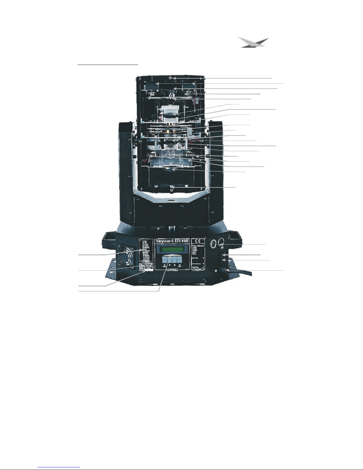
Illustration Varyscan® 6 575 HMI
fixed lense for objectiv
steppermotor shutter/dimmer
steppermotor effectwheel
shutter / dimmer
effectwheel
focus
steppermotor colorwheel
colorwheel
gobowheel
iris
irismotor
spherical lense
steppermotor gobowheel
aspherical lense
bulb
bulbholder
temperatureswitch
reflector
fan
DMX In/Out
fuse bulb
fuse electronic
mainsplug 230V/50Hz
display and buttons for setup of projectors
serialnumber
typesign
channels
Page 5

Varyscan 6 HMI 575
- 5 -
Unpacking of the Varyscan® equipment
First of all take out all parts of the carton.
?? Varyscan® 6 575 HMI
?? These operating instructions
Check, if the delivery contains all parts.
If you notice a damage through transportation, please inform immediately your dealer. Also in case of noticing missing
parts.
Put in/exchange of the bulb
Warning: Before open the projector pull out the mains plug!!!
Loosen the 8 screws at the lid of your Varyscan® 6 575 HMI (head of the
spotlight) with a suitable screw-driver and lift the lid. You can see the bulb holder
in the back third of the head (see page 5) Now loosen the nuts no. 1 and no. 2
and remove the bulb from it’s holder. Put the new 575 HMI bulb into the holder
and tighten the nuts no. 1 and no. 2 manual. The point on the glass of the bulb
should on no account point to the concave mirror, respectively to the lenses
(outline page 4) it should point to the base sheet or to the lid. Take care that the bulb is tightened in the holder.
Warning: Never touch the glass of bulb of the 575 HMI bulb itself!
An adjustment of the bulb is not necessary.
Starting the equipment
Hang up/put up of the Varyscan®
Your Varyscan® 6 is suitable for mounting on a truss or in standing position as well.
2. Cabling of the Varyscan®
Power supply:
A specialist should attach a plug to the open end of the connecting cable, or have the cable connected to 230 Volt / 50
Hertz.
DMX-cabling:
Connect the output of your DMX-controller with the first Varyscan® (controller DMX-Out; Varyscan® DMX-In) with the aid
of a 5 pole XLR-cable. Make sure that in DMX-out of the last Varyscan® there is a resistor (XLR-plug with a resistance of
120 Ohm between pin 2 and pin 3) plugged into.
3. Configuration of Varyscan®
You have many functions at your disposal to adjust your Varyscan® optimal for your use. With a menu-system and the
four keys under the LCD-display you can adjust the functions.
Following the structure of the menu-system.
Page 6

Varyscan 6 HMI 575
- 6 -
E n t e r
S T A N D A L O N E M O D E
0 0 0 - 5 1 2
O N / O F F
O N / O F F
N O R M A L / I N V E R S
N O R M A L / I N V E R S
N O R M A L / L I N E A R
N O R M A L / C H A N G E D
8 B IT /1 6 B I T
N O . O F S T E P s
E D I T S T E P
1 - 1 0
1 - 1 0
S T E P X X : T I M E
S T E P X X : M o v e
S T E P X X : P A N
S T E P X X : T I L T
S T E P X X : G O B O
S T E P X X : C O LO R
S T E P X X : I R IS
STEP XX: LENSSTEP XX: GOBOROTSTEP XX: SHUTTERX:TIMEX:MOVEX:PANX:TILTX:GOBOX:COLORX:DIMMERX:IRISX:GOBOROTX:EFFECTX:LENSX:SHUTTER0-2550-2550-2550-2550-2550-2550-2550-2550-2550-2550-2550-255
E n t e r
E n t e r
E n t e r
E n t e r
E n t e r
E n t e r
D M X M O D E
D M X A D D R E S S
D M X R E S E T
P A N
C O LO R
T I L T
P A N / T I L T
T E S T - P R O G R A M
1 6 B IT D M X
S T E P X X : D I M M E R
T I M E 2 : 0 0 0 0 0 .0 0
T I M E 1 : 0 0 0 0 0 .0 0
M e n u
E n t e r
E n t e r
E n t e r
E n t e r
C LE A R IN G T IM E
+& -
+ /-
+/ -
+/ -
+/ -
+/ -
+/ -
+/ -
+/ -
E n t e r
E n t e r
E n t e r
+ /-
+ /-
+ /-
+ /-
+ /-
+ /-
+ /-
+/-+/-+/-+/
-
+/ -
+/ -
E n t e r
E n t e r
E n t e r
E n t e r
E n
terEnterEnterEnterEnterEnterEnterEnterEnter+/-+/-+/-+/-+/-+/-+/-+/-+/-+/-+/-+/-EnterMenuMen
u
M e n u
M e n u
M e n u
M e n u
M e n u
M e n u
M e n u
M e n u
M e n u
M e n u
E n t e r
E n t e r
E n t e r
E n t e r
EnterEnterEnterEnterEnterEnterEnterEnterEnterEnte
r
Structure o
f menu-system
+/-
M e n u
M e n u
Page 7

Varyscan 6 HMI 575
- 7 -
Definition of the menu / projector-setup
Read off the working hours of the lamp or of the projector:
After you press the key menu you will see in the display the first point of menu; the time for the working hours of the lamp
(time 2). Would you like to reset this time you have to press at the same time the key + and -. The counter will be reset.
With the key enter you will come to the next point of menu, the working hours of the projector (time 2). You cannot reset
this time.
Selection DMX-Mode / Standalone Mode :
Press the key menu to change into the setup mode of the projector. Now press the key enter until DMX-mode or
standalone-mode appears on the display. Now you can chose with the keys -/+ the desired mode and confirm it with the
key enter. According to your selection the menu-structure changes. The menu-system is divided in two ranges.
DMX-Mode
Adjustment of the DMX-address:
Press the key menu to change into the setup-mode of the projector. Now press
the key enter until the selection DMX-mode / standalone-mode appears on the
display. Confirm the DMX-mode with the key enter. Now you see on the display
the request to give in the address. Therefore you use the keys + and -. If you
press this key longer, the addresses will faster count up or down. If you have
adjust your desired address, confirm it with the key enter and leave the menu with
the key menu. Your Varyscan® 6 575 HMI needs 12 channels (16bit-mode).
Therefore you must adjust the channels of your projector with a distance of 12.
Adjust the addresses according to the following schedule:
Reset on DMX:
If you would like to reset your Varyscan® from your DMX-desk (reset on DMX), turn the function DMX-reset to on.
Therefore change into the setup menu of the projector (DMX-mode). In the DMX-mode range press the key enter until
DMX-reset on/off appears on the display. To activate this function press the key +, to deactivate the key -. Afterwards
confirm your application with the key enter. Now you have the possibility to replace your Varyscan® if you transmit with
your DMX-desk on the gobo-channel (gobo-channel 3) the DMX-amount 255.
Continuously colour changing:
If this function is turned on, each DMX-amount between 0 and 128 correspond to a colour wheel position. So you cannot
only produce half colours but also 1/3 – 2/3 colours or ¼ - ¾ colours. To choose this function, choose in the menu range
DMX-mode of your Varyscan® 6 575 HMI with the key enter the option colour and turn it with the key + and – to on and
confirm it with enter.
Pan normal/invers:
With this function you can invert the moving direction of the x-motors. If your projector moves with ascending DMXamounts on the right side, so the projector moves with ascending DMX-amounts on the left side, if you turn the function
pan on invers. For the selection of this function change into the setup mode of the projector –range DMX-mode – and
confirm it with the key enter until the function pan appears. Now you can change with the keys + and – between normal
and invers classes of rating.
Tilt normal/invers:
With this function you can invert the moving direction of the y-motor. If your projector moves with ascending DMXamounts upwards, so the projector moves with ascending DMX-amounts downwards, if you turn the function tilt to invers.
For the selection of this function change into the setup menu of the projector – range DMX-mode – and confirm it with the
key enter until the function tilt appears. Now you can change with the keys + and – between normal and invers classes of
rating.
projector-number DMX-address
1 1
2 13
3 25
4 37
5 49
6 61
7 73
8 85
9 97
10 109
11 121
12 133
Page 8

Varyscan 6 HMI 575
- 8 -
Pan/Tilt normal/changed
With this function you can change the pan-axis and the tilt-axis i.e. if you put in the function to changed, the projector
moves in tilt-direction if in your controller there is a pan-direction programmed and with a programmed tilt-direction it
moves to pan-direction.
08/16Bit DMX
With this function you can adapt your Varyscan® 6 575 HMI to a 10-channel class of rating, that you can operate the
projector at a DMX-control system with 8bit-DMX for pan/tilt. For the selection of this function, change into the setupmenu of the projector – range DMX-mode – and confirm with the key enter as long as the function 08/16 bit DMX
appears. Now you can change with the keys + and – between 10 and 12 channels (8/16 bit).
Test mode:
To see the variety of the functions of your Varyscan® 6 575 HMI, adjust the Varyscan® in the test mode by pressing the
key menu and after it enter (change into the DMX-mode) as long as the option test mode appears on the display. Now
you can change with the key + to test mode on. For the confirmation you have to press one after the keys enter and
menu. The projector performs a reset and pass subsequently the test mode.
Stand-alone-Mode
Change into the standalone-mode as described above. There you have the following points of menu at your disposal.
Number of steps
With the keys + and – you can enter the number of steps that you want to program. Confirm it with the key enter and you
will come directly to the next point of menu.
Edit step
With the keys + and – you can select, which step of your program you want to program. By confirmation with the key enter
you will come to the selection of the times for the selected step and to the single functions (pan, tilt, gobo, colour, ...) of
the projector. Following you can select the different features of the projector and the different times with the keys + and -.
In the display you see the selected program-step and your selected features or one of the both times (step 01: gobo ?
step 01 and selected feature gobo). For a change of your selection confirm your selected feature with the key enter and
change the value with the keys + and -. The values of the separate features correspond to the DMX-values of the
separate channels. At the both times there are adjustments between 0 and 255 seconds possible. For the confirmation of
you value change leave the level with the key enter. Automatically you will come to the next feature which you can
change with the key enter and afterwards with + and -. The features are saved in the menu in the following order (see
table and page 10).
Menu point of the projector Description of the features
TIME Adjustment of the program hours of operation
MOVE Adjustment of the moving times
PAN Adjustment of the position of the projector (x-axis)
TILT Adjustment of the position of the projector (y-axis)
GOBO Selection of the gobos of the projector
COLOR Selection of the colours of the projector
DIMMER Adjustment of the brightness of the projector
IRIS
Adjustment of the beam size of the projector (no zoom function)
GOBOROT Adjustment of the gobo position or the gobo rotation
EFFECT Selection of different effect filters
LENS Adjustment of the sharpness of the projector
SHUTTER Adjustment of the internal shutter sequences (0-11 flashes/sec)
Page 9

Varyscan 6 HMI 575
- 9 -
Changing gobo
Open the lid of the Varyscan® 6 575 HMI by screwing off the eight screws. Following
screw off the two silver screws at the side of the projector head approximately 8 mm,
through the holes in the arms. Now take out the gobo plug-in unit.
Metal-gobos
Now you can press the gobos at the gobo wheel out of their holder
and put in the new gobos. Take care that the gobo engages exactly
with it’s slits in the holder. If the gobo is put in correctly, it moves
easily inside the holder. Now you can put the plug-in unit into your
Varyscan® and close the lid.
Attention: Never open and close the small straps to change the gobos. The straps will break off!!
Glass-gobos
If you screw off the three screws of the holder you can take away the glass-gobo with the holder. Change the
glass-gobo with the complete holder as desired and screw it on. You get the holders and the silicon glue for the glassgobos at your specialist dealer or manufacturer. Take care that you screw in the screws not straight and not too tight.
Now you can put the plug-in unit into your VS 6 and close the lid.
If your projector is not prepared for glass-gobos or you would like to use more glass-gobos, you must adapt your
projector. For this you need a special montage set (montage ring for glass-gobo, 3 distance cases 2,5*1, 3 screws M2*8),
which you get from your specialist dealer or manufacturer.
Loosen the screws of the old metal-gobo holder and change it to the glass-gobo montage holder. Take care that you
change the 2 mm distance cases with the 1mm distance cases. Following you only must screw in the glass-gobo with the
holder.
Measures gobos
With your Varyscan
®
6 575 HMI you have the chance of using two different gobo sizes.
Gobos JB-size
Outside diameter: 39,50 mm
Use diameter: 28,13 mm
Advantage: Because of the notches with a depth of 1 mm which
are arranged in a 120°-division, it is guaranteed that the gobos do
not move in the gobo holder on the gobo wheel as i.e. at other
manufacturers.
Would you like to produce gobos so please request for our exact
technical drawings.
To open the cover
please open
these screws
metallgobo
holder for E-size-gobo
distanceringe 2mm
39,
5 m
m
2
8
,
1
3
m m
Notches at 120° angles
3,2mm wide, 1mm deep
Page 10

Varyscan 6 HMI 575
- 10 -
Standard size: (E-size)
Outside diameter: 37,50 mm
Use diameter: 28,13 mm
Glass-gobo: (E-size)
Outside diameter: 37,50 mm
Use diameter: 28,13 mm
max. thickness 3,00 mm
B Service instructions
Repair of defects
Defect
The appliance does not work at all
1. Check the 8 ampere fuse for the bulb of the
projector and change it, if it is defect.
2. Check the 4 ampere fuse for the electronic of the
projector and change it, if it is defect.
The bulb of the applicance does not shine, but
electronics are working,
i.e. motors are working
1. Check the 8 ampere fuse of the projector and
change it, if it is defect.
2. The bulb is defect. Change it.
3. The temperature switch of the projector is released.
Plug out your Varyscan® and after approximately 15
minutes plug it in again. Check now, if the ventilator
in the head of the projector works and if it is clean. If
the ventilator is defect, have it exchanged by a
specialist or the producer. If the projector turns off
again, please contact your dealer.
The bulb of the appliance shines but the motors and the
ventilators does not work.
1. Check the 4 ampere fuse for the electronic of the
projector and change it, if it is defect.
2. Check the fuses inside the projector on the display
main-board and change it, if it is defect.
DMX-input does not work Check the DMX-address adjustment in the display
Page 11

Varyscan 6 HMI 575
- 11 -
Adjustment of the „motor brake‘‘
We adjust the motor brake at the production of the projector. Normally it is not
necessary y to adjust it. The motor brake (at your Varyscan® 6 only at the gobo
wheel) is principally at all scans of JB-lighting in the projector the same. It consists
of 3 special parts (special kind of disc, steel part, teflon disc). This three parts
must have the following order:
No. 1. Motor
No. 2. small round springs
No. 3. steel part
No. 4. teflon disc
No. 5. the part which has to be installed.
Part no. 5 has to be pushed on the axis of the stepper motor until the parts no. 2 cannot be compressed anymore. After
remove the part no. 5 about 0,5 mm and turn the fasting screws. Now the motor-brake is optimum adjusted.
Regular Maintenance Performances
Warning: Before open the appliance pull out the mains plug!
Open the casing by turning out the screws at the top of the projector.
To be able to take out the modules of your Varyscan® you have to screw off two screws of silver at the side-piece, up to
the mark of the modules. Now you are able to take out the modules.
Attention: Do not forget to lock in the modules after having completed your maintenance performances, by screwing
in the screws of silver carefully!
1. Cleaning of the optical parts:
You should clean the optical parts of your Varyscan® periodically to restore maximum brightness of the projector. After
having opened the casing as explained above, take out the modules and put them on a hard underlay in front of you. Now
you can clean with a fuzz-free rag and a detergent for windows the colour filters of the colour wheel and glass-gobos on
the gobo wheel. Following clean the filters of the effect wheel, the focus lens and the objective lens of the projector. Now
put the modules into the projector and lock them.
2. Cleaning of the ventilation:
You should regularly check the function of the ventilators (base / head). Above all take care that the ventilation inlets and
the interior of the Varyscan® are free from fuzzes and other dust. Open the lid of the head and the base by screwing off
the screws from the lids. Now clean your Varyscan® carefully with a vacuum cleaner. Now close the projector.
Attention: Take care that you do not twist or damage any parts while cleaning your projector!
The guarantee will expire at damages because of inexpert use!!!
3. Lubrication of rotating gobos:
Procure a syringe with a thin needle, customary in trade (grind off the
tip, so it will be blunt – no risk of injury!!), and fill it with our special oil.
On no account use another kind of oil because our oil is a special
mixture. Now syringe the oil between the brass gear wheels and the
brass plate and turn the rotating gobos by hand.
Attention: Do not use too much oil!!!
put a little bit oil
at this place at
every gobogear
Page 12

Varyscan 6 HMI 575
- 12 -
General Information about DMX512-record
The DMX 512-record is divided in 512 addresses. You have 512 addresses for your disposal. To be able to connect
different appliances with a DMX-controller, it is necessary to determine the number of DMX-channel for every appliance.
The occupation of channels of a projector could be like that for example:
Channel 1 X-Movement
Channel 2 Y-Movement
Channel 3 Gobo / Effect wheel
Channel 4 Colour
Channel 5 Shutter / Dimmer
Channel 6 Iris / gobo positioning / gobo rotation
In order that not every connected DMX-appliance performs same functions, the appliances are addressed in series; i.e.
for the first appliance the first six addresses are used (be right for an appliance with six channels), for the second one
(appliance with 6 channels) the next 6 addresses of all the DMX-addresses are used (see for example Varyscan® 6 575
HMI page 11).
Occupation of channels Varyscan® 6 575 HMI
Channel 1 X-movement
Channel 2 Y-movement
Channel 3 Gobo
Channel 4 Colour
Channel 5 Dimmer
Channel 6 Iris
Channel 7 Rotating gobos (positioning and rotating)
Channel 8 Effect wheel
Channel 9 Focus
Channel 10 Shutter
Channel 11 Pan-fine
Channel 12 Tilt fine
channel no. 1 Pan movement 370°
channel no. 2 Tilt movement 270°
channel no. 3 Gobo
gobo 0 (Beam) DMX 000 - 031
gobo 1 DMX 032 - 063
gobo 2 DMX 064 - 095
gobo 3 DMX 096 - 127
gobo 4 DMX 128 - 159
gobo 5 DMX 160 - 255
if function DMX-Reset is at on
gobo 5 DMX 160 - 254
Reset DMX 255
Channel no. 4 Colour
colour 0 (white) DMX 000 - 007
colour 1 (white/red) DMX 008 - 015
colour 2 (red) DMX 016 - 023
colour 3 (red/yellow) DMX 024 - 031
colour 4 (yellow) DMX 032 - 039
colour 5 (yellow/pink) DMX 040 - 047
colour 6 (pink) DMX 048 - 055
colour 7 (pink/green) DMX 056 - 063
colour 8 (green) DMX 064 - 071
colour 9 (green/orange) DMX 072 - 079
Page 13

Varyscan 6 HMI 575
- 13 -
colour 10 (orange) DMX 080 - 087
colour 11 (orange/blue) DMX 088 - 095
colour 12 (blue) DMX 096 - 103
colour 13 (blue/aqua) DMX 104 - 111
colour 14 (aqua ) DMX 112 - 119
colour 15 (aqua white) DMX 120 - 127
colour wheel rotation speed 1 (slow) DMX 128 colour wheel rotation speed 7 (fast) DMX 255
channel no. 5 Dimmer / Shutter
dimmer (linear) DMX 000 - 255
channel no. 6 Iris
iris (linear) DMX 000 - 255
channel no. 7 Rotating gobos (positioning and rotation)
0° DMX 000
180° DMX 063
360° DMX 126
540° DMX 191
rotation left (fast) DMX 192
rotation left (slow) DMX 222
rotation stop DMX 223 - 224
rotation right (slow) DMX 225
rotation right (fast) DMX 255
channel no. 8 Effect wheel
Open DMX 000 - 031
artificial light filter DMX 032 - 063
daylight filter DMX 064 - 095
Prism DMX 096 - 111
Shaking prism (slow) DMX 112 Shaking prism (fast) DMX 127
Open DMX 128 - 159
Floodfilter DMX 160 - 175
flood linear DMX 176 - 223
Open DMX 224 - 255
channel no. 9 Focus
focus (linear) DMX 000 - 255
channel no. 10 Shutter
shutter closed DMX 000 - 010
shutter slow to fast DMX 011 - 240
Shutter open DMX 241 - 255
channel no. 11 Pan movement fine
channel no. 12 Tilt movement fine
Occupation DMX-In / DMX-Out
DMX-In DMX-Out
Pin No. Signal Colour of wire Pin No. Signal Colour of wire
1 Ground black 1 Ground black
2 DMX - white 2 DMX - white
3 DMX + red 3 DMX + red
4 free 4 free
5 free 5 free
Technical data
Measurements:
Page 14

Varyscan 6 HMI 575
- 14 -
Weight: 20 Kilo
Power consumption: ca. 900VA
Mains voltage: 230V 50Hz 3,9A compensated
Bulb: Osram 575 HMI
Fuse 1 bulb: 8 ampere inert (5*20)
Fuse 2 electronic: 4 ampere inert (5*20)
Fuse 3 main board 12V 6,3 ampere inert (5*20)
Fuse 4 main board 24V 4 ampere inert (5*20)
Change of Eprom / Software update
To change the eproms proceed as follows:
Take away the bottom lid of the projector by taking away the four rubber stoppers and the screws. Also take away at the
head of the projector the lid of the objective by screwing off the 11 screws.
1. Display of the main board in the base of the projector
After removing the lid of the bottom lid you can see in the middle of the display main board the eprom. Change it with the
new one.
2. Effect main board in the head of the projector
After removing the lid of the objective you can see under the shutter the eprom for the effect main board. Change it with
the new one.
Attention: Pay attention to the polarity of the eproms!!
(The inlet of the eprom has to point to the same direction as the inlet of the IC holder)
Close the bottom and the head of the projector. Plug in your Varyscan® and please test all functions.
174
310
452
1 2 2
4 1 2
303
360
303
360
386
535
183
283
182
 Loading...