

Page 1

JB-lighting Lichtanlagentechnik GmbH
Sallersteigweg 15 D-89134 Blaustein-Wippingen
Telefon ++49(0)7304-9617-0
Telefax ++49(0)7304-9617-99
http://www.jb-lighting.de
Varyscan 3 Special 250MSD
Varyscan 3 Special Plus 250MSD
English
Bedienungsanleitung
User Manual
Version 2.0
Deutsch
Page 2

Varyscan 3 Special 250MSD
3
JB-lighting Lichtanlagentechnik GmbH Sallersteigweg 15 D-89134 Blaustein Tel. 07304-9617-0
Inhaltsverzeichnis / Contents
english
1. ...................................
2. Installation ......................................
3. ............................
4.
5. ............................
Indroduction
Operation ............
Maintenance ...................................
Troubleshooting
1.1 ..................................
1.2 ........................
1.3 ...............................
2.1
2.2 .........
2.3 ............................
2.4 DMX ...............................
2.5 ........
3.1 ........................................
3.2 ..
3.3 .............................
3.4 ........................................
3.5 ..
3.6
3.7 ...................
3.8 .................................
3.9 .............................
4.1 ...............................
4.2 ...............................
5.1 ..........
5.2 ..................
5.3 ..............................
5.4 ......................................
General Remarks
Unpacking .....................
Technical Data .......
Installing a plug on the power cord .......
Installing or changing the lamp ...
Rigging the fixture .....
wiring ............
Powering the fixture ......................
DIP switches .
Select 6 channel or 8 channel mode ...
DMX settings ...........
DMX protocol
DMX protocol 6 channel mode ..........
DMX protocol 8 channel mode .............
Optimizing lamp allignment
Focussing the unit
Changing the gobos
Cleaning the fixture
Cleaning the optics
Changing thermal fuse ................
Changing Eprom (software)
Pin assignment .......
Circuit diagram
4
5
7
12
13
4
4
4
5
5
5
6
6
7
7
7
8
9
10
11
11
12
12
12
13
13
13
14
16
17
19
24
25
16
16
16
17
17
17
18
18
19
19
19
20
21
22
23
23
24
24
24
25
25
25
26
Deutsch
1. Einleitung ........................................
2. Installation ......................................
3. Inbetriebnahme ..............................
4. Regelmäßige Wartungsarbeiten ..
5. Fehlerbehebung ............................
1.1 Allgemeines ...........................................
1.2 Auspacken der Geräte ..........................
1.3 Technische Daten ..................................
2.1 Netzstecker montieren ..........................
2.2 Leuchtmittel wechseln/einsetzen...........
2.3 Montage der Geräte ..............................
2.4 DMX Verkabelung .................................
2.5 Netzstrom verkabeln .............................
3.1 DIP Schalter ..........................................
3.2 Umstellung 6-Kanal/8-Kanal Betrieb .....
3.3 DMX Adressierung ................................
3.4 Kanalbelegung ......................................
3.5 DMX-Belegung beim 6-Kanalbetrieb ....
3.6 DMX-Belegung beim 8-Kanalbetrieb ...
3.7 Leuchtmittel justieren ...........................
3.8 Optik scharfstellen ...............................
3.9 Gobos wechseln ..................................
4.1 Gerät reinigen ......................................
4.2 Optik reinigen ......................................
5.1 Temperatursicherung wechseln ...........
5.2 Eprom (Software) wechseln ................
5.3 Steckerbelegungen ..............................
5.4 Stromlaufplan .......................................
Page 3
Varyscan 3 Special 250MSD
4
JB-lighting Lichtanlagentechnik GmbH Sallersteigweg 15 D-89134 Blaustein Tel. 07304-9617-0
1. Einleitung
1.1 Allgemeines
Der Varyscan 3 verfügt über 1 Farbrad mit 10 Vollfarben, 1 Vierfarbeneffekt
und weiß. 12 Gobos, davon sind 6 auswechselbar. Farbradrotation in verschiedenen
Geschwindigkeiten. Effektrad mit Prisma, Floodfilter,Tageslichtfilter und Kunstlichtfilter.
Dimmer und Highspeed Shutter. Beim Varyscan 3 Special sind die
6 auswechselbaren Gobos drehbar und positionierbar.
Plus
1.2 Auspacken der Geräte
Öffnen Sie den Karton an der Oberseite und ziehen Sie das Gerät samt Inlays
nach oben aus dem Karton. Nun können Sie die Inlays vom Varyscan entfernen.
Sollten Sie einen Transportschaden am Gerät feststellen, teilen Sie diesen
bitte sofort dem Transportunternehmen und Ihrem Händler mit.
Gewicht: 12kg
Netzanschluß:
230V 50Hz
Stromaufnahme:
ohne Kompensation 3.2A
mit Kompensation 1.8A
Leuchtmittel: PHILIPS 250MSD
OSRAM 250HSD
Max.
Umgebungstemp.: 50°C
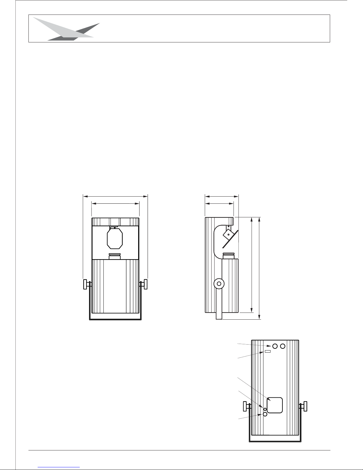
1.3 Technische Daten
244
146
DMX-Buchsen
DIP-Schalter
Netzanschluß
Sicherung 5AT
322
172
500
535
Lüfter
Page 4

Varyscan 3 Special 250MSD
5
2. Installation
2.1 Netzstecker montieren
Die Montage des Schukosteckers, bzw. der Anschluss des Varyscans
an die Stromversorgung (230 Volt, 50 Hertz), muß von einem autorisierten
Fachmann durchgeführt werden.
ACHTUNG: Nur von einem Fachmann durchführen lassen !
2.2 Leuchtmittel wechseln/einsetzen
ACHTUNG: Gerät vom Netz trennen und mindestens 30 Minuten abkühlen lassen !
1
Abbildung: Gerät von hinten
Leuchtmittel: PHILIPS 250MSD oder OSRAM 250HSD
Entfernen Sie die beiden Schrauben
Nr.1 (siehe Abbildung rechts)
Nun können Sie das Fassungsblech
nach hinten aus dem Lampenschacht
ziehen.
Beim Einsetzen der Lampe ist darauf
zu achten, dass Sie den Lampenkolben
nicht mit bloßen Händen berühren.
Immer nur an der Fassung (Keramik)
anfassen.
Schieben Sie nun die Fassung wieder
in den Lampenschacht und achten Sie
darauf, dass die Kabel nicht beschädigt
werden.
Fassungsblech
2.3 Montage der Geräte
Um die optimale Funktionsfähigkeit der Varyscan auszuschöpfen, sollten Sie die Scans
so hoch wie möglich aufhängen. Es empfiehlt sich, den Varyscan mit dem Spiegel
noch oben aufzuhängen. Bei der Installation mit dem Spiegel nach unten,
kann die Lebensdauer des Leuchtmittels herabgesetzt und die Funktion
der Temperatursicherung eingeschränkt werden.
Alle Varyscan sollten im selben Winkel hängen, das heißt, der gedachte Winkel
zwischen Lot und Varyscan sollte bei allen Geräten gleich sein.
ACHTUNG: Mindestens 1m Abstand zu brennbaren Gegenständen !
Varyscan immer mit Sicherungsseil zusätzlich sichern !
braun Phase “L”
blau Nulleiter “N”
grün/gelb Schutzleiter
JB-lighting Lichtanlagentechnik GmbH Sallersteigweg 15 D-89134 Blaustein Tel. 07304-9617-0
Page 5
Varyscan 3 Special 250MSD
6
2.4 DMX Verkabelung
Die DMX Verkabelung (Signalleitungen) sollte mit einem 2-poligen Kabel mit
Abschirmung durchgeführt werden. Wir empfehlen ein DMX-Kabel, es kann jedoch
alternativ auch Mikro-Kabel verwendet werden. Stecker und Buchsen sind 3-pol
XLR, und können im Fachhandel erworben werden.
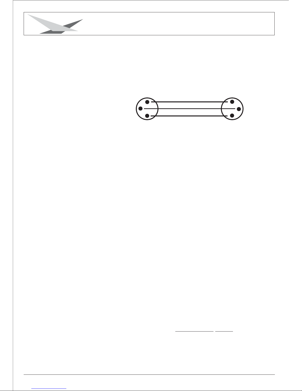
Steckerbelegung
Pin 1 = Ground = Abschirmung
Pin 2 = DMX - = blau
Pin 3 = DMX + = rot
1
2
3
1
2
3
Die DMX Kabel von Varyscan zu Varyscan werden eins zu eins verbunden.
Am Controller befindet sich meistens eine 5-pol XLR Buchse.
Beim Anlöten werden Pin 4 und 5 nicht belegt.
Verbinden Sie nun den Ausgang Ihres Controllers mit dem 1. Varyscan.
(Controller DMX-Out mit Varyscan DMX-In). Anschließend den 2. Varyscan
mit dem 1. Varyscan (Varyscan 1 DMX-Out mit Varyscan 2 DMX-In) und so
weiter. Beim letzten Gerät bleibt die Buchse DMX-Out unbelegt. In manchen
Fällen ist es ratsam einen so genannten Endstecker (XLR-Stecker mit einem
Widerstand von 120 Ohm zwischen Pin 2 und Pin 3) einzustecken. Ob ein
Endstecker benötigt wird hängt von verschiedenen Faktoren (unter anderem
den benutzten Kabellängen und der Anzahl der Geräte) ab. Solange jedoch
keine Probleme in der DMX-Linie auftreten, kann darauf verzichtet werden.
Kabel
2.5 Netzstrom verkabeln
Netzstecker montieren siehe Kapitel 2.1.
Anschlußwerte: Spannung 230V, Frequenz 50Hz, Leistung 740VA (3.2A)
Es sollten jedoch mindestens 920VA (4A) zur Verfügung gestellt werden,
da das Gerät beim Hochfahren mehr Strom benötigt.
Die elektrische Sicherheit des Gerätes ist nur dann gewährleistet, wenn es
an ein vorschriftsmäßig installiertes Schutzleitersystem angeschlossen wird.
Es ist sehr wichtig, dass diese grundlegende Sicherheitsvoraussetzung
erfüllt ist. Lassen Sie im Zweifelsfall die Elektroinstallation durch einen
Fachmann überprüfen.
Der Hersteller kann nicht für Schäden verantwortlich gemacht werden, die
durch einen fehlenden oder unterbrochenen Schutzleiter verursacht werden !
(z.B. Elektrischer Schlag).
Benutzen Sie das Gerät nur in komplett zusammengebauten Zustand, damit
keine elektrischen Bauteile berührt werden können.
Wenn Sie die aufgeführten Punkte beachtet haben, können Sie die Geräte
einstecken, oder von einem Fachmann an das Netz anschließen lassen.
(Lebensgefahr 5000V)
JB-lighting Lichtanlagentechnik GmbH Sallersteigweg 15 D-89134 Blaustein Tel. 07304-9617-0
Page 6
Varyscan 3 Special 250MSD
7
3. Inbetriebnahme
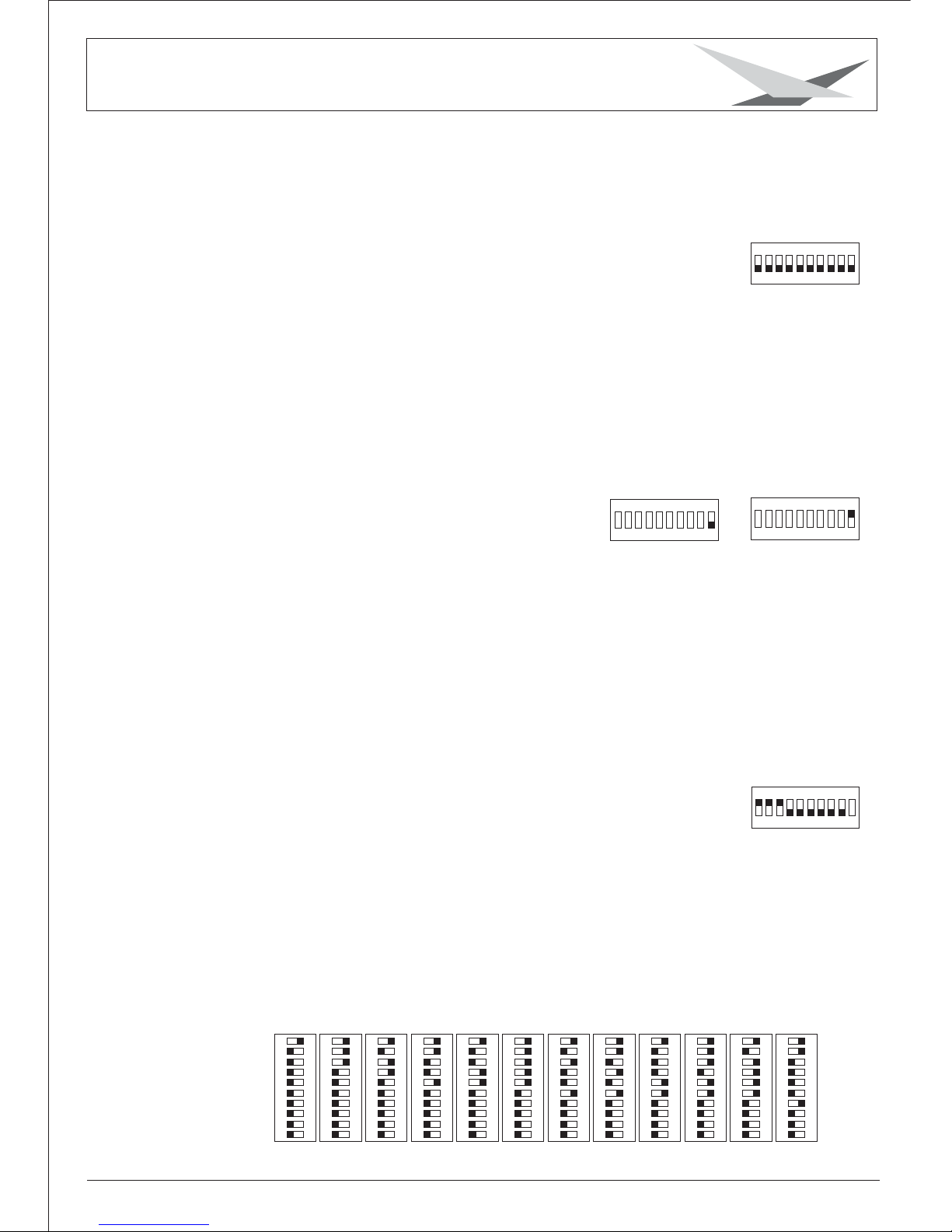
3.1 DIP-Schalter
Mit dem DIP-Schalter, der sich hinten am Gerät befindet,
(s läßt sich der Varyscan auf
die verschiedenen Betriebsarten einstellen.
iehe Seite 4 Technische Daten),
-1
-2
-4
-8
-16
-32
-64
-128
-256
-Mode
DIPON
12345
678910
3.2 Umstellung 6-Kanal / 8-Kanal Betrieb
Der Varyscan kann im 6-Kanal oder 8-Kanal Modus betrieben
werden, abhängig vom verwendeten Controller.
Der Vorteil beim 8-Kanalbetrieb besteht darin, dass jeder
Effekt über einen separaten Kanal gesteuert werden kann
und somit die Programmierung einfacher ist.
Sollte Ihr Controller nur für 6-Kanäle konzipiert sein,
müssen Sie den Varyscan auf 6-Kanal einstellen.
DMX-Ausgabe bei JB-lighting Lichtmischpulten:
JB-lighting DMX-Controller 6-Kanal
JB-lighting ScanControl 6-und 8-Kanal
JB-lighting LICON 1 6-und 8-Kanal
-1
-2
-4
-8
-16
-32
-64
-128
-256
-Mode
DIPON
12345
678910
-1
-2
-4
-8
-16
-32
-64
-128
-256
-Mode
DIP
ON
12345
678910
6-Kanal
8-Kanal
DIP-Schalter 10
auf OFF
DIP-Schalter 10
auf ON
3.3 DMX Adressierung
Mit den Schaltern 1-9 am DIP-Schalter werden die DMX Adressen
(Startadressen) eingestellt.
Der Varyscan benötigt 6 oder 8 DMX Kanäle.(Siehe Kapitel 3.2)
D.h. wenn der erste Varyscan auf “Startadresse 1” adressiert ist
und 6 DMX Kanäle benötigt, werden die Kanäle 1 bis 6 fortlaufend
belegt. Der nächste freie Kanal ist also “7”, deshalb muß Varyscan
2 auf Startadresse “7” adressiert werden. Doppelbelegungen sind
zu vermeiden.
Beispiel zur DMX Adressierung “Kanal 7”
Die Zahl 7 setzt sich aus den Zahlen 1+2+4 zusammen.
Im binären Zahlensystem gilt folgende Zuordnung: 1 =1, 2= 2,3=4,
4=8,5=16usw.FürdieStartadresse 7 müssen die Schalter 1,2 und 3
auf ON gestellt und der Rest bis Schalter 9 bleibt auf OFF. Siehe Beispiel.
-1
-2
-4
-8
-16
-32
-64
-128
-256
-Mode
DIPON
12345
678910
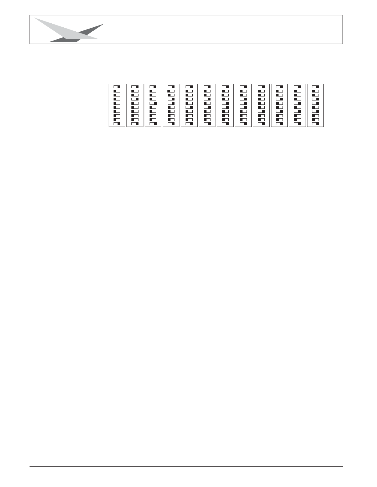
Einstellungen der ersten 12 Varyscan beim 6-Kanal Betrieb.
DIPON
12345
678910
DIP
ON
12345
678910
DIP
ON
12345
678910
DIP
ON
12345
678910
DIP
ON
12345
678910
DIP
ON
12345
678910
DIP
ON
12345
678910
DIP
ON
12345
678910
DIP
ON
12345
678910
DIP
ON
12345
678910
DIP
ON
12345
678910
DIP
ON
12345
678910
Varyscan Nr. 1234 56 789101112
DMX-Adresse 1 7 13 19 25 31 37 43 49 55 61 67
JB-lighting Lichtanlagentechnik GmbH Sallersteigweg 15 D-89134 Blaustein Tel. 07304-9617-0
Page 7
Varyscan 3 Special 250MSD
8
DIP
ON
12345
678910
Einstellungen der ersten 12 Varyscan beim 8-Kanal Betrieb.
DIP
ON
12345
678910
DIP
ON
12345
678910
DIP
ON
12345
678910
DIP
ON
12345
678910
DIP
ON
12345
678910
DIP
ON
12345
678910
DIP
ON
12345
678910
DIP
ON
12345
678910
DIP
ON
12345
678910
DIP
ON
12345
678910
DIP
ON
12345
678910
Varyscan Nr. 1234 56 789101112
DMX-Adresse 1 9 17 25 33 41 49 57 65 73 81 89
Kanal 1 X(Pan) Bewegung
Kanal 2 Y(Tilt) Bewegung
Kanal 3 Gobo+Effektrad
Kanal 4 Farbe
Kanal 5 Shutter+Dimmer
Kanal 6 Special: nicht belegt
Special Plus: Goborotation
6-Kanalbetrieb
Kanal 1 X(Pan) Bewegung
Kanal 2 Y(Tilt) Bewegung
Kanal 3 Gobo
Kanal 4 Farbe
Kanal 5 Shutter+Dimmer
Kanal 6 nicht belegt
Kanal 7 Special: nicht belegt
Special Plus: Goborotation
Kanal 8 Effektrad
8-Kanalbetrieb
3.4 Kanalbelegung
JB-lighting Lichtanlagentechnik GmbH Sallersteigweg 15 D-89134 Blaustein Tel. 07304-9617-0
Page 8

Varyscan 3 Special 250MSD
9
Kanal 4
Farbe 01 weiß
Farbe 02 gelb
Farbe 03 pink dunkel
Farbe 04 hellblau
Farbe 05 grün
Farbe 06 blau
Farbe 07 rot
Farbe 08 türkis
Farbe 09 pink hell
Farbe 10 orange
Farbe 11 magenta
Farbe 12 4-farb
Farbe 11 magenta
Farbe 10 orange
Farbe 09 pink hell
Farbe 08 türkis
Farbe 07 rot
Farbe 06 blau
000-015
016-023
024-031
032-039
040-047
048-055
056-063
064-071
072-079
080-087
088-095
096-111
112-119
120-127
128-135
136-143
144-151
152-159
Kanal 5
Kanal 6 (nur bei Special Plus)
Farbe 05 grün
Farbe 04 hellblau
Farbe 03 pink dunkel
Farbe 02 gelb
Farbe 01 weiß
Farbradrotation
Dimmer/Shutter zu
Dimmer 0-100%
Dimmer offen
Shutter langsam-schnell
Shutter offen
Goboposition stufenlos0-360°
Goborotation stufenlos links
Goborotation STOP
Goborotation stufenlos rechts
160-167
168-175
176-183
184-191
192-199
201-255
000
001-127
128-139
140-243
244-255
000-191
192-222
223-224
225-255
JB-lighting Lichtanlagentechnik GmbH Sallersteigweg 15 D-89134 Blaustein Tel. 07304-9617-0
3.5 DMX-Belegung beim 6-Kanalbetrieb
X(Pan) Bewegung 170°
Y(Tilt) Bewegung 110°
Gobo 1 ohne Effekt
Gobo 1 mit Kunstlichtfilter
Gobo 1 mit Tageslichtfilter
Gobo 1 mit Prisma
Gobo 1 mit Floodfilter
Gobo 2 ohne Effekt
Gobo 2 mit Kunstlichtfilter
Gobo 2 mit Tageslichtfilter
Gobo 2 mit Prisma
Gobo 3 ohne Effekt
Gobo 3 mit Kunstlichtfilter
Gobo 3 mit Tageslichtfilter
Gobo 3 mit Prisma
Gobo 4 ohne Effekt
Gobo 4 mit Kunstlichtfilter
Gobo 4 mit Tageslichtfilter
Gobo 4 mit Prisma
Gobo 5 ohne Effekt
Gobo 5 mit Kunstlichtfilter
Gobo 5 mit Tageslichtfilter
Gobo 5 mit Prisma
Gobo 6 ohne Effekt
Gobo 6 mit Kunstlichtfilte
Gobo 6 mit Tageslichtfilter
Gobo 6 mit Prisma
Gobo 7 ohne Effekt
Gobo 7 mit Kunstlichtfilter
Gobo 7 mit Tageslichtfilter
Gobo 7 mit Prisma
Gobo 8 ohne Effekt
Gobo 8 mit Kunstlichtfilter
Gobo 8 mit Tageslichtfilter
Gobo 8 mit Prisma
Gobo 9 ohne Effekt
Gobo 9 mit Kunstlichtfilter
Gobo 9 mit Tageslichtfilter
Gobo 9 mit Prisma
Gobo 10 ohne Effekt
Gobo 10 mit Kunstlichtfilter
Gobo 10 mit Tageslichtfilter
Gobo 10 mit Prisma
Kanal 1
Kanal 2
Kanal 3
000-255
000-255
000-003
004-007
008-011
012-015
016-019
020-023
024-027
028-031
032-035
036-039
040-043
044-047
048-051
052-055
056-059
060-063
064-067
068-071
072-075
076-079
080-083
084-087
088-091
092-096
096-099
100-103
104-107
108-111
112-115
116-119
120-123
124-127
128-131
132-135
136-139
140-143
144-147
148-151
152-155
156-159
160-163
DMX
DMX
DMX
Gobo 11 ohne Effekt
Gobo 11 mit Kunstlichtfilter
Gobo 11 mit Tageslichtfilter
Gobo 11 mit Prisma
Gobo 12 ohne Effekt
Gobo 12 mit Kunstlichtfilter
Gobo 12 mit Tageslichtfilter
Gobo 12 mit Prisma
Reset (Initialisieren)
164-167
168-171
172-175
176-179
180-183
184-187
188-191
192-254
255
Page 9

Varyscan 3 Special 250MSD
10
JB-lighting Lichtanlagentechnik GmbH Sallersteigweg 15 D-89134 Blaustein Tel. 07304-9617-0
3.6 DMX-Belegung beim 8-Kanalbetrieb
X(Pan) Bewegung 170°
Y(Tilt) Bewegung 110°
Gobo 01
Gobo 02
Gobo 03
Gobo 04
Gobo 05
Gobo 06
Gobo 07
Gobo 08
Gobo 09
Gobo 10
Gobo 11
Gobo 12
Reset über DMX
Farbe 01 weiß
Farbe 02 gelb
Farbe 03 pink dunkel
Farbe 04 hellblau
Farbe 05 grün
Farbe 06 blau
Farbe 07 rot
Farbe 08 türkis
Farbe 09 pink hell
Farbe 10 orange
Farbe 11 magenta
Farbe 12 4-farb
Kanal 1
Kanal 2
Kanal 3
Kanal 4
000-255
000-255
000-015
016-031
032-047
048-063
064-079
080-095
096-111
112-127
128-143
144-159
160-175
176-254
255
000-015
016-023
024-031
032-039
040-047
048-055
056-063
064-071
072-079
080-087
088-095
096-111
DMX
DMX
DMX
DMX
Farbe 11 magenta
Farbe 10 orange
Farbe 09 pink hell
Farbe 08 türkis
Farbe 07 rot
Farbe 06 blau
Farbe 05 grün
Farbe 04 hellblau
Farbe 03 pink dunkel
Farbe 02 gelb
Farbe 01 weiß
Farbradrotation
Dimmer/Shutter zu
Dimmer 0-100%
Dimmer offen
Shutter langsam-schnell
Shutter offen
Goboposition stufenlos 0-360°
Goborotation stufenlos links
Goborotation STOP
Goborotation stufenlos rechts
offen
Kunstlichtfilter
Tageslichtfilter
Prisma
Wackelprisma
Floodfilter
Kanal 5
Kanal 6 (frei)
Kanal 7 (nur bei Special Plus)
Kanal 8
DMX
DMX
DMX
DMX
112-119
120-127
128-135
136-143
144-151
152-159
160-167
168-175
176-183
184-191
192-199
201-255
000
001-127
128-139
140-243
244-255
000-191
192-222
223-224
225-255
000-031
032-063
064-095
096-111
112-127
128-255
Page 10

Varyscan 3 Special 250MSD
11
JB-lighting Lichtanlagentechnik GmbH Sallersteigweg 15 D-89134 Blaustein Tel. 07304-9617-0
3.7 Leuchtmittel justieren
Schalten Sie Ihren Varyscan ein und richten Sie den Beam mit Gobo
Nr.1(großer Beam), ohne Farbe im 90° Winkel auf eine helle Wand.
Der Abstand zur Wand sollte zwischen 6 und 12m liegen. Lösen Sie die
Schrauben Nr.1 (siehe Abbildung rechts) und verschieben Sie das
Fassungsblech solange, bis die maximale Ausleuchtung des Beams
erreicht ist. Drehen Sie die beiden Schrauben Nr.1 wieder fest.
1
Abbildung: Gerät von hinten
Fassungsblech
3.8 Optik scharfstellen
Projizieren Sie ein Gobo auf die gewünschte Distanz, lösen Sie dann
die Rändelschraube am Objektivrohr und verschieben Sie das
Objektiv solange, bis die optimale Projektionsschärfe erreicht ist.
Page 11

Varyscan 3 Special 250MSD
12
JB-lighting Lichtanlagentechnik GmbH Sallersteigweg 15 D-89134 Blaustein Tel. 07304-9617-0
4.2 Optik reinigen
Sie sollten in regelmäßigen Abständen die optischen Teile reinigen, um wieder die
maximale Helligkeit und die maximale Abbildungsqualität zu erreichen.
Hierzu öffnen Sie die Geräteabdeckung und reinigen den Reflektor, die Linsen und
die Farbfilter mit einem fusselfreien Tuch und etwas Glasreiniger. Sie können
auch Q-Tips oder eine Pinzette zu Hilfe nehmen.
Beim Reinigen des Reflektors sollte das Leuchtmittel vorher entfernt werden,
damit es nicht beschädigt wird.
4. Regelmäßige Wartungsarbeiten
4.1 Gerät reinigen
ACHTUNG: Gerät vom Netz trennen und mindestens 30 Minuten abkühlen lassen !
ACHTUNG: Gerät vom Netz trennen und mindestens 30 Minuten abkühlen lassen !
Sie sollten in regelmäßigen Abständen die Funktion des Lüfters überprüfen.
Vor allem sollten Sie darauf achten, dass die Lufteinlässe und das Innere des Varyscan
frei von Fusseln und Staub sind.
Hierzu öffnen Sie die Gehäuseabdeckung, indem Sie die Kreuzschlitzschrauben
entfernen. Nun können Sie den Varyscan mit einem Pinsel und
einem Staubsauger säubern. Achten Sie darauf, daß Sie beim Reinigen keine
Teile verbiegen oder beschädigen. Bei Schäden, die auf unsachgemäße Handhabung
zurückzuführen sind, erlischt die Garantie!
3.9 Gobos wechseln
ACHTUNG: Gerät vom Netz trennen und
mindestens 30 Minuten abkühlen lassen !
Entfernen Sie die 8 Schrauben am Abdeckblech Ihres Varyscan und nehmen
dieses ab. Jetzt können Sie, mit einem geeigneten Schraubendreher,
die drei Schrauben am jeweiligen Gobo lösen und das Gobo entnehmen.
Achten Sie beim Special Plus darauf, dass Sie die richtigen
Schrauben entfernen. (Siehe Skizze rechts)
Wenn Sie eigene Gobos herstellen lassen wollen,
beachten Sie bitte folgende Zeichnung.
Nutzdurchmesser: (Platz für Ihr Motiv) 12mm
Befestigungslöcher: Teilkreisdurchmesser 19,5mm
Lochdurchmesser klein 2,1mm
Lochdurchmesser groß 4,1mm
Aufteilung 6x60°
12mm
25mm
Diese Schrauben lösen
Bei den anderen Schrauben
ist im Gobo ein größeres Loch.
Diese nicht lösen!!!
Page 12

Varyscan 3 Special 250MSD
13
JB-lighting Lichtanlagentechnik GmbH Sallersteigweg 15 D-89134 Blaustein Tel. 07304-9617-0
JP1
JP2
JP3
JP4
JP5
JP6
JP7
JP8
JP9
JP10
JP11
S1
S2
Bezeichnung
DMX-In
SM Effektrad
12V Eingang
SM Goborad
SM Farbrad
Lüfter Ausgang
SM Goborotation
SM Dimmer 1
SM X-Achse
SM Y-Achse
SM Dimmer 2
DMX-In
DMX-Out
Pin 1
frei
rot
braun
rot
rot
frei
rot
rot
rot
rot
rot
schwarz
schwarz
Pin 2
schwarz
blau
braun
blau
blau
frei
blau
blau
blau
blau
blau
weiß
weiß
Pin 3
rot
gelb
----gelb
gelb
schwarz
gelb
gelb
gelb
gelb
gelb
rot
rot
Pin 4
weiß
weiß
----weiß
weiß
rot
weiß
weiß
weiß
weiß
weiß
-----
-----
5. Fehlerbehebung
5.1 Temperatursicherung wechseln
5.2 Eprom (Software) wechseln
5.3 Steckerbelegungen
Entfernen Sie das Platinenabdeckbleck hinter der Spiegelablenkung,
indem Sie die vier Kreuzschlitzschrauben herausdrehen.
Wenn Sie nun die Platine mit dem Stromlaufplan Seite 14 vergleichen,
können Sie das Eprom erkennen. Hebeln Sie das alte Eprom vorsichtig
aus der Fassung und tauschen Sie es gegen das neue Eprom aus.
Achten Sie darauf, dass die Einbuchtung am Eprom deckungsgleich mit der Einbuchtung
an der Fassung ist, und dass alle Füßchen vom Eprom richtig in der Fassung stecken.
Schrauben Sie das Platinenabdeckblech wieder an seinen Platz und testen Sie den
Varyscan.
ACHTUNG: Gerät vom Netz trennen und mindestens 30 Minuten abkühlen lassen !
ACHTUNG: Gerät vom Netz trennen und mindestens 30 Minuten abkühlen lassen !
ACHTUNG: Nur von einem Fachmann durchführen lassen !
Entfernen Sie die 8 Schrauben an der Gehäuseabdeckung des Varyscan und nehmen Sie
diese ab. Reinigen Sie Ihr Gerät (siehe 4.1 Seite 12).
Lösen Sie nun die Mutter am Zünder mit einem passenden Gabelschlüssel und klappen
Sie den Zünder, ohne die Kabel zu lösen aus dem Gerät. Die Temperatursicherung ist
im Kabel, welches von der Sicherung zur Drossel geht eingelötet und mit einem
Silikon-Gewebeschlauch umhüllt.
Löten Sie das Kabelende von der Sicherung ab und ziehen Sie es nach hinten
aus der Kabeldurchführung heraus. Jetzt können Sie den Silikon-Gewebeschlauch von
der Temperatursicherung abziehen und diese austauschen.
Achten Sie darauf, beim Löten die Temperaursicherung nicht zu überhitzen,
da diese sonst zerstört wird. Messen Sie anschließend mit einem Durchgangsprüfer ob
die Temperatursicherung Durchgang hat und stülpen Sie den Silikon-Gewebeschlauch
wieder über die Temperatursicherung. Montieren Sie den Varyscan wieder zusammen.
Der Silikon-Gewebeschlauch ist sehr wichtig, da die Temperatursicherung spannungsführend ist und somit Lebensgefahr besteht. Testen Sie Ihren Varyscan und prüfen
Sie den Lüfter, da ein defekter Lüfter die häufigste Ursache für das Auslösen der
Temperatursicherung ist.
Page 13

Varyscan 3 Special 250MSD
14
JB-lighting Lichtanlagentechnik GmbH Sallersteigweg 15 D-89134 Blaustein Tel. 07304-9617-0
+
+
+
U2
R3
S1
U3
C5
R6
U1
U4
Q2
Q1
C6
JP3
JP6
JP2
JP7
JP4
JP8
JP11
JP5
C36
C33
R25
JP9
JP10
JP1
C40
R28
R28
R33
R32
U16
U18
C39
C39
R27
C48
C48
C50
R30
R35
R34
U15
U13
U17
U10
C41
R26
C46
D3
C45
C43
R31
C51
C52
C53
U9
U12
C44
C49
C49
R29
C19
U7
C4
R13
R14
R14
C20
C18
F1
D1
R1
Y1
R5
R2
R4
C2
C1
C11
C10
R15
R8
R7
R19
R16
C9
U5
U11
R18
R10
R9
R12
R11
U8
U6
R17
C30
C14
C17
U14
R24
R23
R21
C31
C35
R20
R22
C32
C37
C38
C21
Schrittmotor
Dimmer 1
Schrittmotor
Farbrad
Schrittmotor
Goborad
Schrittmotor
Goborotation
Schrittmotor
Effektrad
Schrittmotor
X-Achse
Schrittmotor
Y-Achse
Schrittmotor
Dimmer 2
5.4 Stromlaufplan
Drossel
250 Watt
Drossel
250
Watt
Zünder
Trafo
Sicherung
5AT
Temperatursicherung
93°C
Konden-
sator
L
N
DLaN
blau
braun
Lüfter
12V
DMX-In
DMX-Out
Eprom
S2
S1
Page 14

Varyscan 3 Special 250MSD
15
JB-lighting Lichtanlagentechnik GmbH Sallersteigweg 15 D-89134 Blaustein Tel. ++49-7304-9617-0
1. ...................................
2. Installation ......................................
3. ............................
4.
5. ............................
Indroduction
Operation ............
Maintenance ...................................
Troubleshooting
1.1 ..................................
1.2 ........................
1.3 ...............................
2.1
2.2 .........
2.3 ............................
2.4 DMX ...............................
2.5 ........
3.1 ........................................
3.2 ..
3.3 .............................
3.4 ........................................
3.5 ..
3.6
3.7 ...................
3.8 .................................
3.9 .............................
4.1 ...............................
4.2 ...............................
5.1 ..........
5.2 ..................
5.3 ..............................
5.4 ......................................
General Remarks
Unpacking .....................
Technical Data .......
Installing a plug on the power cord .......
Installing or changing the lamp ...
Rigging the fixture .....
wiring ............
Powering the fixture ......................
DIP switches .
Select 6 channel or 8 channel mode ...
DMX settings ...........
DMX protocol
DMX protocol 6 channel mode ..........
DMX protocol 8 channel mode .............
Optimizing lamp allignment
Focussing the unit
Changing the gobos
Cleaning the fixture
Cleaning the optics
Changing thermal fuse ................
Changing Eprom (software)
Pin assignment .......
Circuit diagram
16
17
19
24
25
16
16
16
17
17
17
18
18
19
19
19
20
21
22
23
23
24
24
24
25
25
25
26
Contents
Page 15

Varyscan 3 Special 250MSD
16
JB-lighting Lichtanlagentechnik GmbH Sallersteigweg 15 D-89134 Blaustein Tel. ++49-7304-9617-0
The Varyscan 3 is equipped with one colourwheel with 10 colours, one multicolour effect
plus white. 12 gobos, six of them interchangeable. Rainbow effect in different speeds,
effect wheel with prism, floodfilter, daylight filter and conversion filter, dimmer and high
speed shutter. In addition the six interchangeable gobos of Varyscan 3 Special
are rotatable and indexable.
Plus
weight : 12 kg
power supply:
230V 50Hz
current consuption
without compensation: 3.2A
with compesation: 1.8A
lamp: PHILIPS 250MSD
OSRAM 250HSD
max.
ambient temperature: 50°C
1.3 Technical Data
244
146
DMX connector
DIP switch
mains connection
fuse 5AT
322
172
500
535
fan
1. Indroduction
1.1 General Remarks
1.2 Unpacking
Open the top of the box and remove the unit with the inlays. Remove the
inlays from the Varyscan.
For any damage occuring during transport, report to the transport company
immediately.
Page 16

Varyscan 3 Special 250MSD
17
JB-lighting Lichtanlagentechnik GmbH Sallersteigweg 15 D-89134 Blaustein Tel. ++49-7304-9617-0
2. Installation
1
Backside view
Lampholder
brown live “L”
blue neutral
“N”
yellow/green ground
2.1 Installing a plug on the power cord
Install a 3-prong gounding type plug that fits your supply.
Connected load: voltage 230V, frequency 50Hz, Power 340 VA
Warning: To ensure propper installation of the plug consult a qualified
technician!
2.2 Installing or changing the lamp
Warning: Disconnect fixture from mains, and allow hot lamp to cool down
for at least 30 minutes!
lamp type: PHILIPS 250MSD or OSRAM 250HSD
Remove both screws
no.1 (see drawing)
Remove lamp holder gently from the case
by pulling it backwards.
If changing the lamp, remove old lamp from
lamp socket. Hold the new lamp only by its
ceramic base. Never touch the glass bulb.
Insert the new lamp in the lamp socket.
Re-insert the lamp holder and tighten the
scews. Make sure the cables do not get
damaged during the process.
2.3 Rigging the fixture
Warning: Keep fixtures at least 1 m away from inflamable articles!
Always use a safety cable attached to the fixture!
Best performace of Varyscans is reached by rigging the units as high as possible.
The angle between trussing system and Varyscan has to be the same with every unit.
To ensure propper performance of thermal fuse it is better not to install the fixtures
upside down. Attach a safety cable to every fixture.
Page 17

Varyscan 3 Special 250MSD
18
JB-lighting Lichtanlagentechnik GmbH Sallersteigweg 15 D-89134 Blaustein Tel. ++49-7304-9617-0
Pin assignment
Pin 1 = shield
Pin 2 = data - = blue
Pin 3 = data + = red
1
2
3
1
2
3
2.4 DMX wiring
Use a shielded twisted-pair cable to connect the serial link. For short distances a
microphone cable may be used.
Use 3-pin XLR connectors.
The pin assignment is the same for all Varyscans in line.
If the output socket of the control desks offers a 5 pin XLR female socket,
pin 4 and 5 are not occupied.
Connect the DMX-out of the control desk to the first Varyscan in line.
(lighting control desk DMX-Out / Varyscan DMX-In). Connect the second
Varyscan to the first in line, and so on (Varyscan 2 DMX-In / Varyscan 1
DMX-Out). The DMX-Out of the last unit in line is not occupied unless
problems occure. Then use a termination plug with the last Varyscan in line.
(XLR-connector with a 120 Ohm resistor soldered between pin 2 and pin 3).
Problems might occure when the line is overloaded, e.g.
signal cable
2.5 Powering the fixture
Install a plug like described in 2.1.
Connected load: Voltage 230Volts, frequence 50Hz, power 740VA (3,2A)
Use a power supply of at least 920VA (4A) per unit, as the fixture need more
power during the process of powering up.
Connect the fixture to a propper installed grounded system only. If any doubts
on the electrical installations occur, consult a qualified electrician.
In case of damages occuring due to a not propper installed electrical system,
warranty claims will be invalidated.
Don´t use fixtures when top cover is not fixed propperly. Contact with electronical
parts can result in risk for life.
Connect fixture only after assuring that the electrical installation fits your demands
(Electrical shock 5000V)
Page 18

Varyscan 3 Special 250MSD
19
JB-lighting Lichtanlagentechnik GmbH Sallersteigweg 15 D-89134 Blaustein Tel. ++49-7304-9617-0
-1
-2
-4
-8
-16
-32
-64
-128
-256
-Mode
DIPON
12345
678910
The Varyscan can be opperated either in 6 channel or 8
channel mode depending on the lighting control console.
The main advantage of the 8 channel mode is that every
effect is assinged to a seperate channel. Programming
therefore is less complicated.
If your lighting control console is only able to control 6
channels per unit, you have to assign the Varyscan to
6 channel mode.
DMX-output of JB-lighting consoles:
JB-lighting DMX-Controller 6 channel
JB-lighting ScanControl 6 and 8 channel
JB-lighting LICON 1 6 and 8 channel
-1
-2
-4
-8
-16
-32
-64
-128
-256
-Mode
DIPON
12345
678910
-1
-2
-4
-8
-16
-32
-64
-128
-256
-Mode
6 channel
8 channel
DIP switch 10
OFF
DIP switch 10
ON
-1
-2
-4
-8
-16
-32
-64
-128
-256
-Mode
DIPON
12345
678910
DIPON
12345
678910
Varyscan No. 1234 56 789101112
DMX address 1 7 13 19 25 31 37 43 49 55 61 67
3. Operation
3.1 DIP switches
The DIP switches are located on the backside of the unit.
The are used to define the different operation modes and
to enter start address.
(See page 16 technical data)
3.2 Select 6 channel or 8 channel mode
3.3 DMX settings
Use DIP switch 1-9 to assign the Varyscan to its address or start channel.
The Varyscan requires either 6 or 8 DMX channes, depending on the
actual mode (see chapter 3.2)
When using the Varyscans in 6 channel mode each unit requires 6 DMX channels.
If the first fixture in line is addressed to starting channel no. 1 the second
unit has to be addressed to channel no. 7. Never occupy one channel twice!
The third Varyscan in line has to be addressed to channel no. 13 and so on.
Example for DMX setting to channel no. “7”
Using the binary system the figure 7 consists of the figures 1+2+3 = 7.
DIP switch one is assigned to figure 1. DIP switch two is assigned to figure 2. DIP
switch three is assigned to figure no. 4. DIP switch four is assigned to figure no.8.
DIP switch five is assigend to figure no. 16 and so on. Switch DIP switch 1,2
and 3 to “on” to assign the Varyscan to start channel no. 7. Leave the rest of
the DIP switches in an “off” position.
Assignment of the first 12 Varyscan in line (6 channel mode)
DIP
ON
12345
678910
DIP
ON
12345
678910
12345
678910
DIP
ON
12345
678910
DIPONDIP
ON
12345
678910
DIP
ON
12345
678910
DIP
ON
12345
678910
DIP
ON
12345
678910
DIP
ON
12345
678910
12345
678910
DIP
ON
12345
678910
DIPONDIP
ON
12345
678910
Page 19

Varyscan 3 Special 250MSD
20
JB-lighting Lichtanlagentechnik GmbH Sallersteigweg 15 D-89134 Blaustein Tel. ++49-7304-9617-0
DIP
ON
12345
678910
DIP
ON
12345
678910
DIP
ON
12345
678910
DIP
ON
12345
678910
DIP
ON
12345
678910
DIP
ON
12345
678910
DIP
ON
12345
678910
DIP
ON
12345
678910
DIP
ON
12345
678910
DIP
ON
12345
678910
DIP
ON
12345
678910
DIP
ON
12345
678910
Varyscan No. 1234 56 789101112
DMX address 1 9 17 25 33 41 49 57 65 73 81 89
Assignment of the first 12 Varyscan in line (8 channel mode)
3.4 DMX protocol
channel no. 1 Pan movement
2 Tilt movement
3 gobo+effect wheel
4 colour
5 shutter+dimmer
6 Special: no function
Special Plus: gobo rotation
6 channel mode
channel no.
channel no.
channel no.
channel no.
channel no.
1 Pan movement
2 Tilt movement
3 gobo
4 colour
5 shutter+dimmer
6 no function
7 Special: no function
Special Plus: gobo rotation
8 effect wheel
8 channel mode
channel no.
channel no.
channel no.
channel no.
channel no.
channel no.
channel no.
channel no.
Page 20

Varyscan 3 Special 250MSD
21
JB-lighting Lichtanlagentechnik GmbH Sallersteigweg 15 D-89134 Blaustein Tel. ++49-7304-9617-0
channel 4
colour 01 white
colour 02 yellow
colour 03 dark pink
colour 04 light blue
colour 05 green
colour 06 blue
colour 07 red
colour 08 cyan
colour 09 light pink
colour 10 amber
colour 11 magenta
colour 12 4-colours
colour 11 magenta
colour 10 amber
colour 09 light pink
colour 08 cyab
colour 07 red
colour 06 blue
000-015
016-023
024-031
032-039
040-047
048-055
056-063
064-071
072-079
080-087
088-095
096-111
112-119
120-127
128-135
136-143
144-151
152-159
channel 5
channel 6 (only Special Plus)
colour 05 green
colour 04 light blue
colour 03 dark pinkl
colour 02 yellow
colour 01 white
rainbow effect
dimmer/shutter closed
dimmer 0-100%
dimmer open
shutter slow-high speed
shutter open
gobo position 0-360°
gobo rotation left
gobo rotation stop
gobo rotation right
160-167
168-175
176-183
184-191
192-199
201-255
000
001-127
128-139
140-243
244-255
000-191
192-222
223-224
225-255
3.5 DMX protocol 6 channel
Pan movement 170°
Tilt movement 110°
gobo 01
gobo 01 with conversionf.
gobo 01 with daylight filter
gobo 01 with prism
gobo 01 with floodfilter
gobo 02
gobo 02
gobo 02
gobo 02
gobo 03
gobo 03
gobo 03
gobo 03
gobo 04
gobo 04
gobo 04
gobo 04
gobo 05
gobo 05
gobo 05
gobo 05
gobo 06
gobo 06
gobo 06
gobo 06
gobo 07
gobo 07
gobo 07
gobo 07
gobo 08
gobo 08
gobo 08
gobo 08
gobo 09
gobo 09
gobo 09
gobo 09
gobo 10
gobo 10
gobo 10
gobo 10
channel 1
channel 2
channel 3
without effect
without effect
with conversionf.
with daylight filter
with prism
without effect
with conversionf.
with daylight filter
with prism
without effect
with conversionf.
with daylight filter
with prism
without effect
with conversionf.
with daylight filter
with prism
without effect
with conversionf.
with daylight filter
with prism
without effect
with conversionf.
with daylight filter
with prism
without effect
with conversionf.
with daylight filter
with prism
without effect
with conversionf.
with daylight filter
with prism
without effect
with conversionf.
with daylight filter
with prism
000-255
000-255
000-003
004-007
008-011
012-015
016-019
020-023
024-027
028-031
032-035
036-039
040-043
044-047
048-051
052-055
056-059
060-063
064-067
068-071
072-075
076-079
080-083
084-087
088-091
092-096
096-099
100-103
104-107
108-111
112-115
116-119
120-123
124-127
128-131
132-135
136-139
140-143
144-147
148-151
152-155
156-159
160-163
DMX
DMX
DMX
gobo 11
gobo 11
gobo 11
gobo 11
gobo 12 without effect
gobo 12
gobo 12
gobo 12
reset
without effect
with conversionf.
with daylight filter
with prism
with conversionf.
with daylight filter
with prism
164-167
168-171
172-175
176-179
180-183
184-187
188-191
192-254
255
Page 21

Varyscan 3 Special 250MSD
22
JB-lighting Lichtanlagentechnik GmbH Sallersteigweg 15 D-89134 Blaustein Tel. ++49-7304-9617-0
3.6 DMX protocol 8 channel
Pan movement 170°
Tilt movement 110°
gobo 01
gobo 02
gobo 03
gobo 04
gobo 05
gobo 06
gobo 07
gobo 08
gobo 09
gobo 10
gobo 11
gobo 12
reset
colour 01 white
colour 02 yellow
colour 03 dark pink
colour 04 light blue
colour 05 green
colour 06 blue
colour 07 red
colour 08 cyan
colour 09 light pink
colour 10 amber
colour 11 magenta
colour 12 4-colours
channel 1
channel 2
channel 3
channel 4
000-255
000-255
000-015
016-031
032-047
048-063
064-079
080-095
096-111
112-127
128-143
144-159
160-175
176-254
255
000-015
016-023
024-031
032-039
040-047
048-055
056-063
064-071
072-079
080-087
088-095
096-111
DMX
DMX
DMX
DMX
colour 11 magenta
colour 10 amber
colour 09 light pink
colour 08 cyan
colour 07 red
colour 06 blue
colour 05 green
colour 04 light blue
colour 03 dark pink
colour 02 yellow
colour 01 white
rainbow effect
dimmer/shutter closed
dimmer 0-100%
dimmer open
shutter slow-fast
Shutter open
gobo position 0-360°
gobo rotation left
gobo rotation stop
gobo rotation right
open
conversion filter
daylight filter
prism
prism swing effect
flood filter
channel 5
channel 6 (no function)
channel 7 (only Special Plus)
channel 8
DMX
DMX
DMX
DMX
112-119
120-127
128-135
136-143
144-151
152-159
160-167
168-175
176-183
184-191
192-199
201-255
000
001-127
128-139
140-243
244-255
000-191
192-222
223-224
225-255
000-031
032-063
064-095
096-111
112-127
128-255
Page 22

Varyscan 3 Special 250MSD
23
JB-lighting Lichtanlagentechnik GmbH Sallersteigweg 15 D-89134 Blaustein Tel. ++49-7304-9617-0
1
Backside view
Lampholder
3.8 Focussing the unit
Project one of the gobos on a wall, at the desired projection distance.
Loosen screw on the objectiv and shift it until projection of the image
is at the desired state. Tighten screw again.
3.7 Optimizing lamp alignment
Switch on the Varyscan and project gobo no. 1 (beam)
on a white wall in a 90° angle. The distance between
Varyscan and wall should be 6 to 12 meters.
Loosen both screws no. 1 (see drawing) and move
lampholder until the light output is at its maximum.
Tighten both screws no. 1 again.
Page 23

Varyscan 3 Special 250MSD
24
JB-lighting Lichtanlagentechnik GmbH Sallersteigweg 15 D-89134 Blaustein Tel. ++49-7304-9617-0
3.9 Changing gobos
Unscrew the 8 screws holding the top cover of the Varyscan and remove
it. The gobos can be removed by loosening the three screws. (See
attached drawing)
For the design of custom made gobos, please have a look at the
enclosed drawing.
Image diameter: 12mm
Mounting holes: reference diameter 19,5mm
diameter small 2,1mm
diameter large 4,1mm
allocation 6x60°
12mm
25mm
unscrew these screws
The mounting holes of the
other screws is larger.
Leave those screws tightened!
Warning: Disconnect fixture from mains, and allow
hot lamp to cool down for at least 30 minutes!
4. Maintenance
4.1 Cleaning the fixture
4.2 Cleaning the optics
Warning: Disconnect fixture from mains, and allow
hot lamp to cool down for at least 30 minutes!
Warning: Disconnect fixture from mains, and allow
hot lamp to cool down for at least 30 minutes!
Regular cleaning of the fixture is most important to keep a good perfomance over a long
period of time. Especially removing dust and grease from the inside as well as cleaning the
fans ensures reliable perfomance of the Varyscan.
Open the cover by loosening the screws. Use a brush and a vacuum cleaner to remove
dust from the inside. Make sure not to bend or damage the mechanical and electorical
parts inside of the fixture.
Incompetend performace of the maintenance will invalidate the warrany claims. Consult
qualified service personnel.
For a maximum light output the optical system has to be cleaned from time to time.
Loosen the screws holding the top cover and remove it.
Remove lamp before cleaning the optical parts of the fixture.
Use a soft cloth and gently whipe reflector, lenses and colour filters. You also may
use a pair of tweezers and a regular glass cleaner.
Page 24

Varyscan 3 Special 250MSD
25
JB-lighting Lichtanlagentechnik GmbH Sallersteigweg 15 D-89134 Blaustein Tel. ++49-7304-9617-0
JP1
JP2
JP3
JP4
JP5
JP6
JP7
JP8
JP9
JP10
JP11
S1
S2
Description
DMX-In
SM effect wheel
12V input
SM gobo wheel
SM colour wheel
fan output
SM gobo rotation
SM dimmer 1
SM movement
SM tilt movement
SM dimmer 2
DMX-In
DMX-Out
pan
Pin 1
not occupied
red
brown
red
red
not occupied
red
red
red
red
red
black
black
Pin 2
black
blue
brown
blue
blue
not o.
blue
blue
blue
blue
blue
white
white
Pin 3
red
yellow
----yellow
yellow
black
yellow
yellow
yellow
yellow
yellow
red
red
Pin 4
white
white
----white
white
red
white
white
white
white
white
-----
-----
5. Troubleshooting
5.1 Change thermal fuse
5.2 Change eprom (software)
5.3 Pin assignment
Remove the circuit board cover which is located behind the mirror holder, by loosening
the screws. Compare the circuit board with the diagram on page 26 to locate the eprom.
Remove the eprom very carefully from the socket and insert the new eprom. The small
mark on the eprom and the eprom socket indicates the right position of the eprom. Make
sure both marks match. Check the pins contact.
Reassemble the cover of the circuit board and test the Varyscans functions.
WARNING: Contact qualified service personnel!
Warning: Disconnect fixture from mains, and allow
hot lamp to cool down for at least 30 minutes!
Warning: Disconnect fixture from mains, and allow
hot lamp to cool down for at least 30 minutes!
Remove the 8 screws holding the top cover of the Varyscan and remove it.
Clean the unit (see chapter 4.1).
Loosen the nut which holds the ignitor and place the ignitor outside the case without
removing the cables. The thermal fuse it located in the cable which runs from ballast
to the fuse.
Unsolder the cable from fuse and remove cable by pulling it backwards. Remove the
silicone fabric hose from the thermal fuse and unsolder it from the cable. Install the
new thermal fuse, but make sure not to overheat it during the process of soldering.
Use a continuity tester to check the continuity and coat the cable and the thermal fuse
again with the fabric hose. The fabric hose is most important, because the thermal
fuse is live.
Reassemble the Varyscan.
Test the fan to ensure it is working. A defective fan is the most common reason for
a defective thermal fuse.
Page 25

Varyscan 3 Special 250MSD
26
JB-lighting Lichtanlagentechnik GmbH Sallersteigweg 15 D-89134 Blaustein Tel. ++49-7304-9617-0
+
+
+
U2
R3
S1
U3
C5
R6
U1
U4
Q2
Q1
C6
JP3
JP6
JP2
JP7
JP4
JP8
JP11
JP5
C36
C33
R25
JP9
JP10
JP1
C40
R28
R28
R33
R32
U16
U18
C39
C39
R27
C48
C48
C50
R30
R35
R34
U15
U13
U17
U10
C41
R26
C46
D3
C45
C43
R31
C51
C52
C53
U9
U12
C44
C49
C49
R29
C19
U7
C4
R13
R14
R14
C20
C18
F1
D1
R1
Y1
R5
R2
R4
C2
C1
C11
C10
R15
R8
R7
R19
R16
C9
U5
U11
R18
R10
R9
R12
R11
U8
U6
R17
C30
C14
C17
U14
R24
R23
R21
C31
C35
R20
R22
C32
C37
C38
C21
Motor
Dimmer 1
Motor
Colourwheel
Motor
Gobowheel
Motor
Goborotation
Motor
Effectwheel
Motor
Pan
Motor
Tilt
Motor
Dimmer 2
5.4 Circuit diagram
Ballast
250 Watt
Ballast
250
Watt
Ignitor
Transformer
Fuse
5AT
Termofuse
93°C
L
N
DLaN
blue
brown
Fan
12V
DMX-In
DMX-Out
Eprom
S2
S1
 Loading...