

Page 1
Deutsch
Version 1.0
2004
JB-lighting Lichtanlagentechnik GmbH
Sallersteigweg 15 D-89134 Blaustein-Wippingen
Telefon +49 (0)7304-9617-0
Telefax +49 (0)7304-9617-99
http://www.jb-lighting.de
English
electronic ballast
Page 2
Inhaltsverzeichnis
1.Einleitung......................................................................
2. Installation...........................................................................
3. Bedienfeld............................................................................
5. Service................................................................................
3.1 Menü-Übersicht........................................................
3.2 Parameter zurücksetzen...........................................
3.3 DMX Adressierung....................................................
3.4 Standalone-Betrieb...................................................
3.5 Leuchtmittel-Steuerung............................................
5.1 Farbscheiben wechseln.............................................
5.2 Leuchtmittel wechseln.............................................
5.3 Gerät reingen..........................................................
5.4 Optik reinigen..........................................................
5.5 Software updaten....................................................
5.6 Stromlaufplan..........................................................
1.1 Allgemeines..................................................................
1.2 Auspacken der Geräte..................................................
1.3 Technische Daten........................................................
2.1 Leuchtmittel einsetzen/wechseln..............................
2.2 Netzstecker montieren..............................................
2.3 Montage der Geräte..................................................
2.4 DMX Verkabelung.....................................................
2.5 Netzstrom verkabeln.................................................
4
5
7
12
15
4
4
4
5
5
6
6
7
8
9
9
9
11
15
16
16
16
17
18
Deutsch
4. Kanalbelegung...................................................................
3
JB-lighting Lichtanlagentechnik GmbH Sallersteigweg 15 D-89134 Blaustein Telefon +49 (0)7304-9617-0
Contents
1. Introduction..............................................................
2. Installation........................................................................
3. Control Panel....................................................................
5. Service...............................................................................
3.1 Menu navigation.....................................................
3.2 Set to factory default..............................................
3.3 DMX addressing.....................................................
3.4 Standalone mode...................................................
3.5 Lamp control and lamp ignition..............................
5.1 Colour wheel replacement.....................................
5.2 lamp replacement..................................................
5.3 Cleaning the fixutre................................................
5.4 Cleaning the optics.................................................
5.5 Software update.....................................................
5.6 Wiring diagram.......................................................
1.1 General Remarks.......................................................
1.2 Unpacking..................................................................
1.3 Technical Data..........................................................
2.1 Installing/Changing the lamp.................................
2.2 Powering the fixture...............................................
2.3 Rigging..................................................................
2.4 DMX wiring.............................................................
2.5 Install a plug on the power cord.............................
20
21
23
28
31
20
20
20
21
21
22
22
23
24
25
25
25
27
31
32
32
32
33
34
English
4. DMX Protocol....................................................................
electronic ballast
Page 3
4
JB-lighting Lichtanlagentechnik GmbH Sallersteigweg 15 D-89134 Blaustein Telefon +49 (0)7304-9617-0
1. Einleitung
1.1 Allgemeines
Der Varycolor P6 575HMI verfügt über 7 Farben plus weiß, CMY-Farbmischung,
Dimmer, Shutter, Beamshape, Frost und ein Zoom.
Die Achsen X und Y(Pan & Tilt) können mit 8Bit oder 16Bit angesteuert werden,
abhängig vom eingesetzten Controller.
1.2 Auspacken der Geräte
Öffnen Sie den Karton an der Oberseite und ziehen Sie die Inlays vom Kopf und
Fuß ab. Nun können Sie das Gerät aus dem Karton entnehmen.
Sollten Sie einen Transportschaden am Gerät feststellen, teilen Sie diesen
bitte sofort dem Transportunternehmen und Ihrem Händler mit.
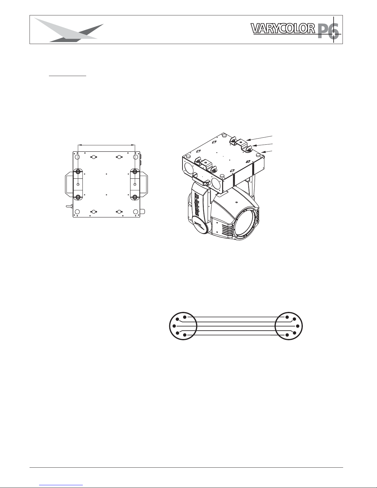
1.3 Technische Daten
Gewicht:
22
kg
Netzanschluß: 115/230V 47-63Hz
Leistung: 900VA
Leuchtmittel: OSRAM HMI 575GS
Max.
Umgebungstemp.:
40°C
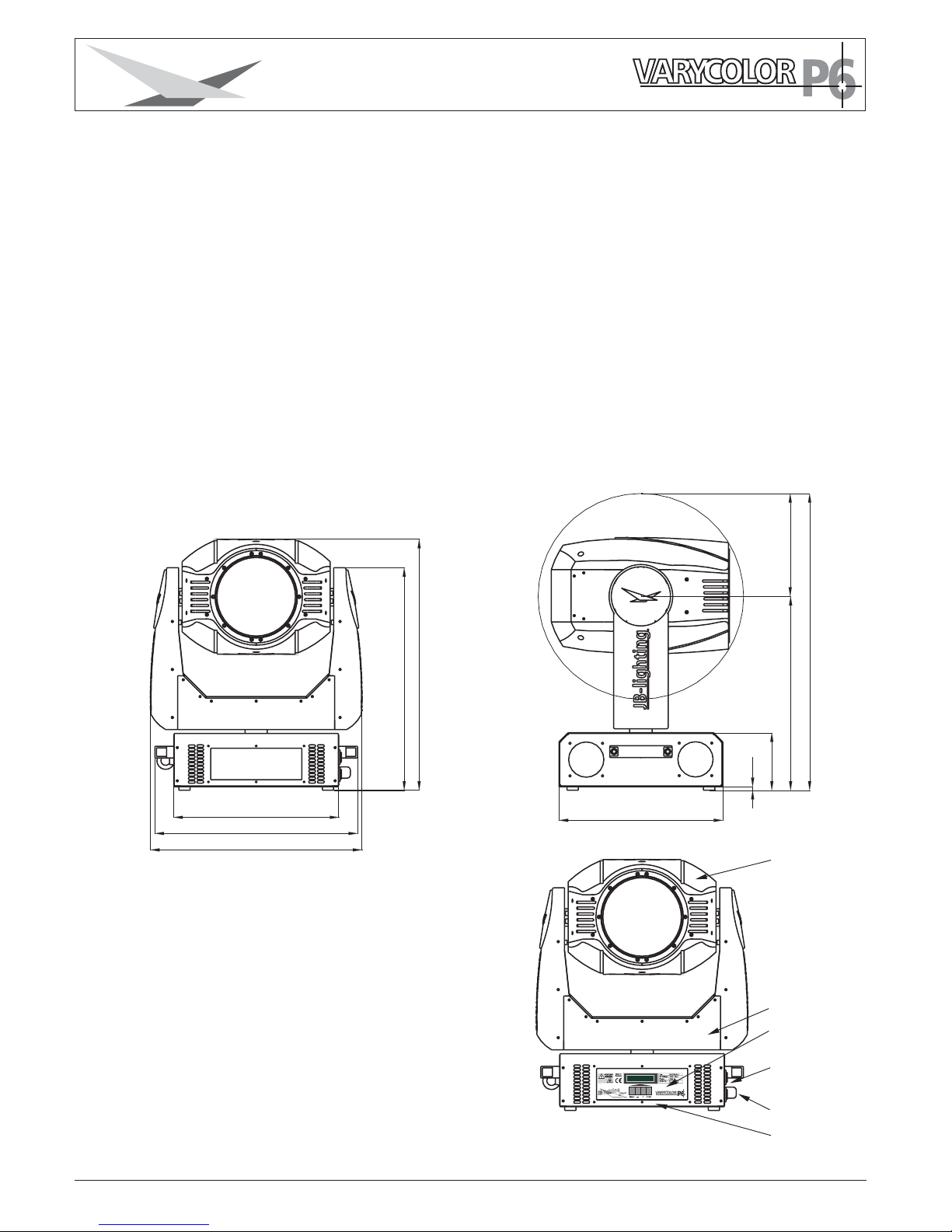
DMX-Buchsen
Fuß
Arm
Kopf
Bedienfeld
Netzanschluß
368
452
471
496
559
226
426
652
360
126.5
8
electronicballast
electronic ballast
Page 4
5
2. Installation
2.2 Netzstecker montieren
Die Montage des Schukosteckers, bzw. der Anschluss des Gerätes
an die Stromversorgung (115/230Volt, 47-63Hz), muß von einem autorisierten
Fachmann durchgeführt werden.
ACHTUNG: Nur von einem Fachmann durchführen lassen !
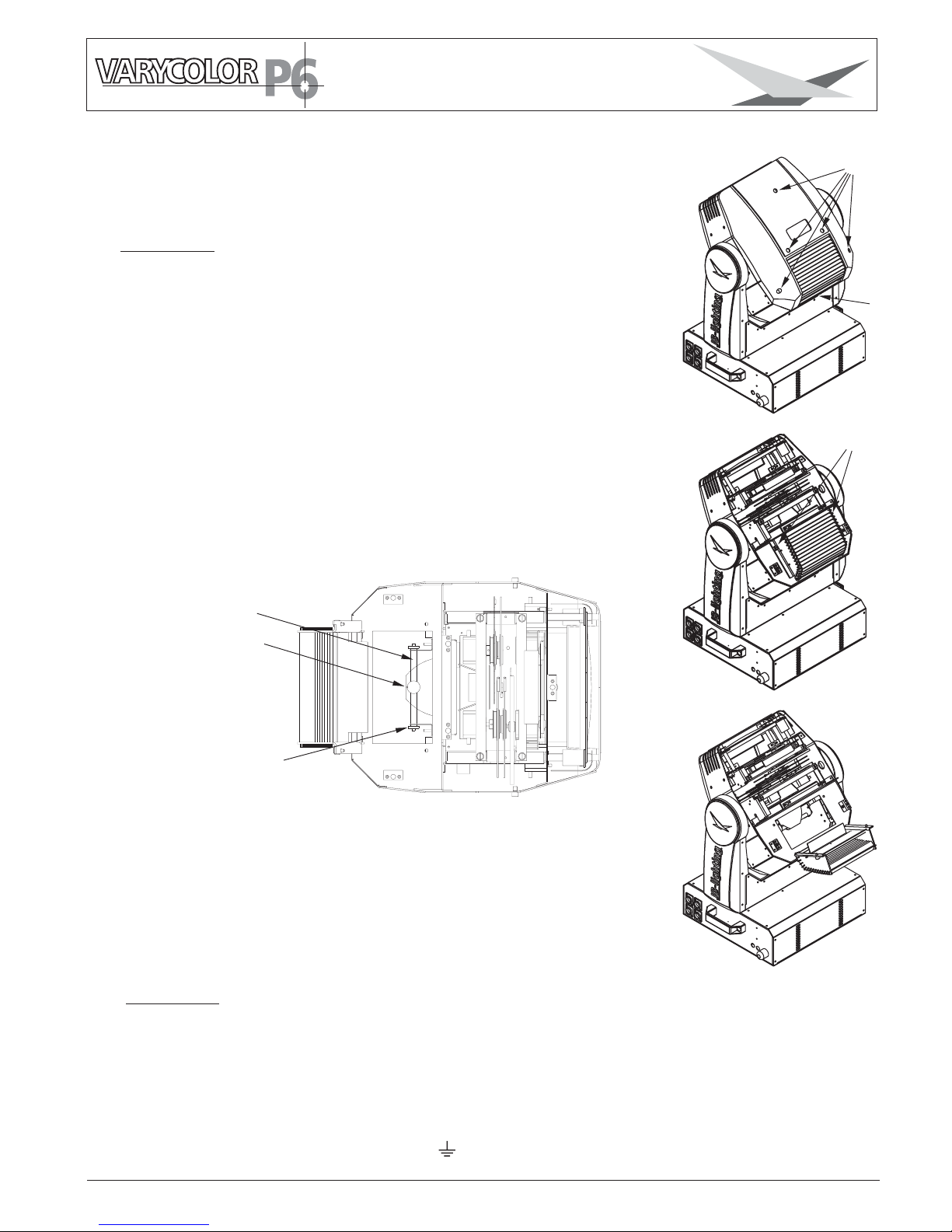
2.1 Leuchtmittel einsetzen/wechseln
ACHTUNG: Gerät vom Netz trennen und mindestens
30 Minuten abkühlen lassen !
Leuchtmittel: OSRAM HMI 575GS
Am Scharnier Nr.1 erkennen Sie wo oben am Kopf ist.
Drehen Sie die 5 Schrauben Nr.2 mit einer halben Umdrehung
nach links und nehmen die Kunststoffabdeckung ab.
Öffnen Sie nun die 2 Rändelschrauben Nr.3 und klappen
den Deckel nach oben.
Nun können Sie das Leuchtmittel in die Fassung einsetzen.
Achten Sie darauf, daß das Leuchtmittel ganz vorne an den
Langlöchern anliegt der Pumpstengel nach hinten zeigt
und die Rändelschrauben angezogen sind.
Beim Einsetzen der Lampe ist darauf zu achten, daß Sie
den Lampenkolben nicht mit bloßen Händen berühren.
Immer nur am Sockel (Metall) anfassen.
braun
Phase
“L”
blau Nullleiter
“N”
grün/gelb Schutzleiter
JB-lighting Lichtanlagentechnik GmbH Sallersteigweg 15 D-89134 Blaustein Telefon +49 (0)7304-9617-0
1
2
3
Leuchtmittel
Pumpstengel
Rändelschraube
electronic ballast
Page 5
6
2.3 Montage der Geräte
Der Varycolor P6 kann auf den Boden gestellt, oder an den vorgesehenen Camloclaschen
senkrecht oder waagerecht montiert werden. Bei der Montage mit den Camloclaschen
müssen immer zwei Camloclaschen verwendet werden und die Camlocs müssen richtig
eingerastet sein.
Varycolor zusätzlich mit Sicherungsseil an der Sicherungsöse sichern.
ACHTUNG: Mindestens 2m Abstand zu brennbaren Gegenständen !
Varycolor immer mit Sicherungsseil zusätzlich sichern !
Sicherungsöse
Camloclasche
Camloc
2.4 DMX Verkabelung
Die DMX Verkabelung (Signalleitungen) sollte mit einem 4-poligen Kabel mit Abschirmung
verkabelt werden. Wir empfehlen ein DMX-Kabel, es kann jedoch alternativ auch ein
2-poliges Mikro-Kabel verwendet werden.Hierbei ist jedoch kein Software-Update zu den
Varycolor möglich, da Pin 4 und 5 in diesem Fall nicht belegt sind..
Bei Stecker und Buchsen handelt es sich um 5-pol XLR. Sie können im Fachhandel
erworben werden.
Steckerbelegung
Pin 1 = Ground = Abschirmung
Pin 2 = DMX Pin 3 = DMX +
Pin 4 = Data out Pin 5 = Data out +
4
2
3
4
2
3
Die DMX Kabel von Varycolor zu Varycolor werden eins zu eins verbunden.
Verbinden Sie nun den Ausgang Ihres Controllers mit dem 1. Varycolor.
(Controller DMX-Out mit Varycolor DMX-In). Anschließend den 1. Varycolor
mit dem 2. Varycolor (Varycolor 1 DMX-Out mit Varycolor 2 DMX-In) und so
weiter. Beim letzten Gerät bleibt die Buchse DMX-Out unbelegt. In manchen
Fällen ist es ratsam einen so genannten Endstecker (XLR-Stecker mit einem
Widerstand von 120 Ohm zwischen Pin 2 und Pin 3) einzustecken. Ob ein
Endstecker benötigt wird hängt von verschiedenen Faktoren (unter anderem
den benutzten Kabellängen und der Geräteanzahl ab). Solange jedoch
keine Probleme in der DMX-Linie auftreten, kann darauf verzichtet werden.
Kabel mit Abschirmung
5
1
5
1
JB-lighting Lichtanlagentechnik GmbH Sallersteigweg 15 D-89134 Blaustein Telefon +49 (0)7304-9617-0
312
electronic ballast
Page 6
7
2.5 Netzstrom verkabeln
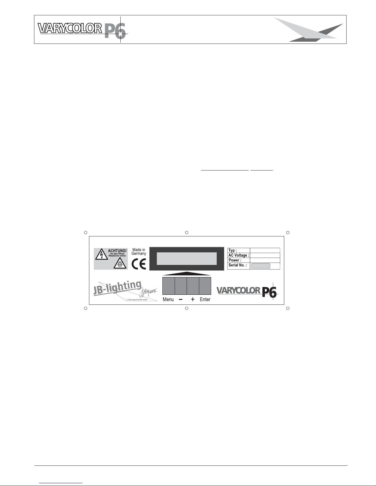
Am Bedienfeld im Fuß des Gerätes können sämtliche Parameter des Varycolor
eingestellt werden. (siehe Menü-Übersicht nächste Seite)
Durch einmaliges Betätigen der Taste Menü gelangen Sie in das Menü.
Mit den Tasten - und + können Sie die einzelnen Menüpunkte aufrufen.
Mit Enter gelangen Sie ins nächste Untermenü. Durch Drücken der Taste Menü
gelangen Sie eine Stufe zurück.
3. Bedienfeld
JB-lighting Lichtanlagentechnik GmbH Sallersteigweg 15 D-89134 Blaustein Telefon +49 (0)7304-9617-0
Netzstecker montieren siehe Kapitel 2.2.
Anschlußwerte: Spannung 110/230V, Frequenz 47-63Hz, Leistung 900VA (8/3,9A)
Es sollten jedoch mindestens 960VA (8,4/4,2A) zur Verfügung gestellt werden,
da das Gerät beim Hochfahren mehr Strom benötigt.
Die elektrische Sicherheit und die Funktion des Gerätes ist nur dann gewährleistet, wenn
es an ein vorschriftsmäßig installiertes Schutzleitersystem angeschlossen wird.
Es ist sehr wichtig, daß diese grundlegende Sicherheitsvoraussetzung vorhanden ist.
Lassen Sie im Zweifelsfall die Elektroinstallation durch einen Fachmann überprüfen.
Der Hersteller kann nicht für Schäden verantwortlich gemacht werden, die durch einen
fehlenden oder unterbrochenen Schutzleiter verursacht werden! (z.B. Elektrischer Schlag).
Benutzen Sie das Gerät nur in komplett zusammengebauten Zustand, damit keine
elektrischen Bauteile berührt werden können.
Wenn Sie die aufgeführten Punkte beachtet haben, können Sie die Geräte
einstecken, oder von einem Fachmann an das Netz anschließen lassen.
(Lebensgefahr 5000V)
VARYCOLOR P6 EVG
900 VA
CAUTION!
Disconnect mains
before opening
electronic ballast
electronic ballast
115/230V 47-63Hz
Page 7
8
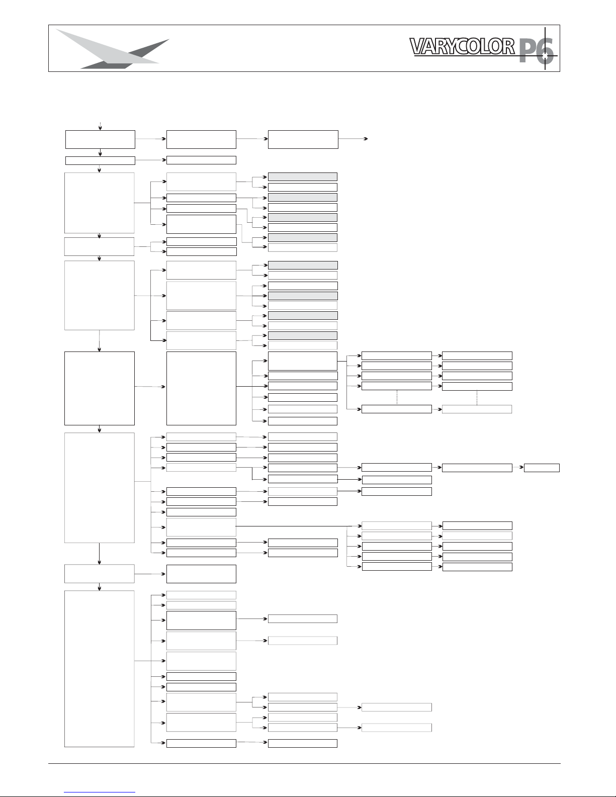
3.1 Menü-Übersicht
(Werkseinstellung)
DMX ADRESS
PAN/TILT
DMX/STANDALONE
(Geräte Parameter)
SERVICE
DMX-TEST
INFO
LOAD DEFAULS
ADRESS +/-
(Auflösung)
PAN INVERS
TILT INVERS
PAN/TILT SWAP
DMX MODE
STANDALONE
STEP NR.
+/-
DMX CHANNEL
SOFTWARE VERSION
FIRMWARE VERSION
REM. LAMP TIME
LAMP STRIKES
TOT LAMP TIME
TEMP BASE
TEMP HEAD PCB.
16 BIT
8 BIT
NORMAL
INVERS
NORMAL
INVERS
NORMAL
(Bild ändern)
INSERT
DELETE
FADE TIME
NEXT TIME
PAN
TILT
MOVE B-OUT
+/+/+/+/-
+/-
RESET?
+/-
+/-
+/-
+/-
+/-
ACTUAL
MAX
ACTUAL
MAX
RESET ?
RESET ?
STANDALONE STEPS
JB-lighting Lichtanlagentechnik GmbH Sallersteigweg 15 D-89134 Blaustein Telefon +49 (0)7304-9617-0
FACTORY DEFAULT
PERSONALITY
RESOLUTION
(tauschen)
(Feinjustierung)
FINE ADJUST
(Lebensdauer Lampe)
(Bertiebsstundenzähler)
(Betriebszähler Lampe)
MODYFY
OFS COLOR
OFS CYAN
OFS MAGENTA
OFS YELLOW
OFS DIMMER
SURE ?
CAPT DMX
RESET FIXTURE
LAMP ON
LAMP OFF
ERROR LIST
FUNCTIONS TEST
INIT PAN TILT
INIT LAMP SENSE
RECEIVESOFT
CROSSLOAD SOFT
SURE ?
LIST
CLEAR
COUNT : 1
START TEST
SURE ?
SURE ?
SURE ?
SURE ?
TOT LAMP STRIKES
TOT OPERATE TIME
LAMP ON/OFF DMX
ON
OFF
SHORTEST DIST.
ON
OFF
(Kürzester Weg)
LAMP MODE
AUTO START
AUTO OFF
AUTO DMX
Taste Menu
+
Enter
Enter
INVERS
Enter
FADE TIME
NEXT TIME
PAN
TILT
MOVE B-OUT
SURE ?
OFS COLOR
OFS CYAN
OFS MAGENTA
OFS YELLOW
OFS DIMMER
SURE ?
COLOR1 TIMEOUT
CLEAR?
AC IN VOLTAGE
??? V
RESET?
TEST RUNNING
PAN/TILT MODE
JB MODE
HOG MODE
RESET STEP
CLEAR ALL
electronic ballast
Page 8

9
3.2 Parameter zurücksetzen
3.4 Standalone-Betrieb
JB-lighting Lichtanlagentechnik GmbH Sallersteigweg 15 D-89134 Blaustein Telefon +49 (0)7304-9617-0
3.3 DMX Adressierung
Durch drücken der Taste + oder - kann die DMX-Adresse verändert werden.
Mit der Taste Enter wird der Wert bestätigt.
Um den VC P6 auf die Werkseinstellung zurück zu setzen, drücken Sie die Taste Menu.
Im Display erscheint die Meldung: Anschließend drücken Sie Taste
Enter und es erscheint . Durch erneutes Drücken der Enter Taste aktivieren
Sie die Abfrage . Durch Bestätigen über die Enter-Taste werden die Parameter auf
Werkseinstellung zurück gesetzt.
FACTORY DEFAULT.
LOAD DEFAULTS
SURE
Im Standalone-Betrieb können Sie zuvor abgespeicherte Bilder als Endlosschleife abrufen.
Die Speicherung der Bilder kann dabei auf zwei Arten erfolgen.
Entweder Sie stellen die gewünschten DMX-Werte direkt am VC P6 ein und speichern
diese ab, oder Sie stellen die DMX-Werte über ein angeschlossenes DMX-Pult ein
und speichern Sie anschließend im VC P6 ab.
Einstellen der DMX-Werte am Gerät
.
Rufen Sie den Standalone-Betrieb folgendermaßen auf:
Drücken Sie zuerst die Taste Menu und anschließend fünf Mal auf die Taste + (siehe Seite 8)
Im Display sehen Sie die Meldung: Bestätigen Sie die Meldung durch
drücken der Taste Enter.
Nun steht im Display die Meldung: die wiederum mit Enter bestätigt
werden muß. Nach der Bestätigung steht die Meldung: im Display. Rufen Sie
das Modify Menü durch Drücken der Enter Taste auf.
Nun haben Sie Zugriff auf sämtliche Parameter des VC P6. Drücken Sie so oft die Taste +,
bis das gewünschte Scheinwerferparameter im Display dargestellt wird, z.B. .
Nun bestätigen Sie die Auswahl mit Enter und geben dann über die Tasten + und - den
gewünschten DMX Wert ein.
Die Abspeicherung der DMX-Werten bestätigen Sie einfach durch Drücken der Taste Enter.
Verlassen Sie das Menü durch Drücken der Taste Menu.
STANDALONE STEPS.
STEP NR. 1/1,
MODIFY 1/1
PAN
Anhängen eines weiteren Schrittes:
Drücken Sie so oft auf die Taste +, bis Sie im Menü-Punkt: sind.
Drücken Sie dann einmal auf die Taste Enter; im Display erscheint die Abfrage:
Bestätigen Sie nun mit der Taste Enter, es wird ein neuer Schritt angehängt.
Die DMX-Werte des vorigen Schritts werden in den neuen Schritt kopiert. Zum Ändern der
DMX-Werte rufen Sie das Modify-Menü auf und verfahren wie oben beschrieben.
INSERT
SURE?
Löschen eines Schrittes:
Rufen Sie das Standalone Menü auf. Im Display muss folgende Meldung stehen:
Nun bestätigen Sie durch Drücken der Taste Enter.
Im Display steht nun folgende Meldung:
Mit der Taste + können Sie nun den gewünschten Schritt aufrufen. Sobald Sie ihn aktiviert
haben drücken Sie die Taste Enter und wählen dann über die Taste + den Menü-Punkt
an. Zum Löschen des Schrittes drücken Sie nun die Taste Enter. Es erfolgt die
Sicherheitsabfrage: Diese Sicherheitsabfrage müssen Sie durch erneutes Drücken
der Taste Enter bestätigen, dann ist der Schritt gelöscht.
STANDALONE STEPS.
STEP NR:1/X
DELETE
SURE?
electronic ballast
Page 9

10
JB-lighting Lichtanlagentechnik GmbH Sallersteigweg 15 D-89134 Blaustein Telefon +49 (0)7304-9617-0
Zurücksetzen der DMX-Werte in einem Schritt:
Sollten Sie die DMX-Werte eine Schrittes zurücksetzen wollen, dann gehen Sie
folgendermaßen vor:
Drücken Sie zuerst die Taste Menu und anschließend fünf Mal auf die Taste +
Im Display sehen Sie die Meldung:
Bestätigen Sie die Meldung durch Drücken der Taste Enter.
Nun steht im Display die Meldung: Rufen Sie durch Drücken der Taste +
den gewünschten Schritt auf und bestätigen Sie mit Enter.
Nun können Sie über die Taste + den Menü-Punkt aufrufen.
Wenn Sie den Menü-Punkt aufgerufen und durch Drücken der Taste Enter bestätigt haben,
erscheint im Display die Sicherheitsabfrage:
Durch erneutes Drücken der Taste Enter bestätigen Sie Ihre Auswahl und die DMX-Werte
des angewählten Schrittes werden auf den Ursprungswert zurückgesetzt.
STANDALONE STEPS
STEP NR. 1/X.
RESET STEP
SURE?
Übernehmen der DMX-Werte von einem externen Pult:
Anhängen eines weiteren Schrittes
Rufen Sie das Standalone Programmier-Menü folgendermaßen auf:
Drücken Sie zuerst die Taste Menu und anschließend fünf Mal die Taste +. Im Display
erscheint die Meldung: . Bestätigen Sie die Auswahl durch Drücken
der Taste Enter und drücken Sie anschließend ein Mal die Taste +
Im Display steht folgende Meldung: Drücken Sie jetzt auf die Taste Enter
um den DMX-Eingang freizuschalten. Im Display erscheint die Meldung:
und der VC P6 reagiert auf die eingestellten DMX-Werte.
Zum Übernehmen drücken Sie die Taste Enter. Im Display steht dann die Meldung:
Anschließend hängen Sie einen Schritt an. .
Dazu drücken Sie ein Mal auf die Taste +. Im Display steht:
Drücken Sie nun die Taste Enter; es erfolgt die Sicherheitsabfrage:
Bestätigen Sie ein weiteres Mal durch Drücken der Taste Enter und im Display wird die
Bestätigung sichtbar:
Um mit dem Programmieren fortzufahren, drücken Sie nun ein Mal die Taste - .
Das Display wird folgende Meldung zeigen:
Schalten Sie den DMX-Eingang frei indem Sie erneut auf die Taste Enter drücken.
Das Display wird wiederum: zeigen.
Wiederholen Sie den oben aufgeführten Vorgang.
Um die am Pult eingestellten Werte zu übernehmen drücken Sie jetzt zwei Mal
die Taste Enter. (Nach dem ersten Drücken steht im Display: ;
nach dem zweiten Drücken:
Nun fügen Sie einen weiteren Schritt wie in Kapitel:
ein und wiederholen diese Vorgänge.
STANDALONE STEPS
CAPT DMX 1/ 1.
DMX CAPTURE
CAPT DMX 1/1.
INSERT 1/1
SURE?
INSERT 2/2
CAPT DMX 2/2
DMX CAPTURE
START CAPTURE
CAPT DMX X / X)
electronic ballast
Page 10

11
JB-lighting Lichtanlagentechnik GmbH Sallersteigweg 15 D-89134 Blaustein Telefon +49 (0)7304-9617-0
3.5 Leuchtmittel-Steuerung
Beim VC P6 stehen folgende Möglichkeiten zur Leuchtmittel-Steuerung zur Verfügung:
Einstellungen zur werden in der Personality Konfiguration im
Menü-Punkt eingestellt
Möglichkeit 1: Das Leuchtmittel zündet, sobald Strom fließt
Möglichkeit 2: Das Leuchtmittel zündet, sobald Strom fließt und auf dem Lamp on/off
Kanal Nr. 5 ein DMX-Wert von 248 - 255 angewählt wird
Möglichkeit 3: Das Leuchtmittel zündet, sobald Strom fließt und ein DMX-Signal
anliegt
Einstellung zur
Unabhängig von den Einstellungen zur Leuchtmittel-Zündung funktioniert die
Leuchtmittel-Steuerung über DMX. Damit das Leuchtmittel über DMX angesprochen
werden kann, muss dies in der Personality Konfiguration unter dem Menü-Punkt
zuerst eingestellt werden.
Wenn im Personality Menü-Punkt der Menüpunkt eingestellt
wurde zündet der VC P6 das Leuchtmittel wie oben beschrieben, es kann aber nur
bei Möglichkeit 2 auch wieder ausgeschaltet werden.
Wenn im Personality Menü-Punkt der Menüpunkt eingestellt
wurde, zündet der VC P6 das Leuchtmittel wie oben beschrieben, es kann aber immer
über DMX wieder ausgeschaltet werden. (Kanal Nr. 5 DMX-Wert von 232-239 länger
als 3 Sekunden).
Leuchtmittel-Zündung
Leuchtmittel-Steuerung:
OFF
ON
LAMP MODE
(AUTO START)
(AUTO OFF)
(AUTO DMX)
LAMP ON/OFF DMX
LAMP ON/OFF DMX
LAMP ON/OFF DMX
Aktivieren des Standalone Betriebs:
Unabhängig davon ob die DMX-Werte der einzelnen Schritte manuell eingegeben oder
von einem Pult übernommen wurden, wird der Standalone-Betrieb im Menü
DMX/STANDALONE eingestellt.
Um das Menü aufzurufen drücken Sie zuerst die Taste Menu und anschließend drei Mal
die Taste +. Im Display steht dann:
Diese Meldung bestätigen Sie durch Drücken der Taste Enter.
Nun können Sie über die Taste + die Standalone-Funktion anwählen und durch einmaliges
Drücken der Taste Enter aktivieren.
Im Display steht folgende Bestätigung:
DMX/STANDALONE.
S-ALONE:1/2
Deaktivieren des Standalone Betriebs:
Um den Standalone-Betrieb zu deaktivieren drücken Sie die Taste Enter.
Anschließend drücken Sie die Taste - und im Display wird folgende Meldung angezeigt:
Drücken Sie nochmals die Taste Enter. Im Display steht dann:
Verlassen Sie das Menü durch Drücken der Taste Menu.
DMX MODE
DMX/STANDALONE.
electronic ballast
Page 11

12
JB-lighting Lichtanlagentechnik GmbH Sallersteigweg 15 D-89134 Blaustein Telefon +49 (0)7304-9617-0
4. Kanalbelegung
JB MODE
HOG MODE
Kanal 1 Pan
Kanal 2 Tilt
Kanal 3 Pan fein
Kanal 4 Tilt fein
Kanal 1 Pan
Kanal 2 Pan fein
Kanal 3 Tilt
Kanal 4 Tilt fein
Kanal 15 Farbrad
Kanal 16 Pan/Tilt Geschw.
Kanal 17 Effektgeschw.
Kanal 18 Blackout Move
Aufteilung der einzelnen Kanäle
Kanal 1 Pan (X) Bewegung
Kanal 2 Tilt (Y) Bewegung
Kanal 3 Pan (X) fein
Kanal 4 Tilt (Y) fein
Kanal 5 Sicherheit
Lampe aus (nach 3 Sekunden)
Reset (nach 1 Sekunde)
Lampe an
Kanal 6 Shutter zu
Shutter auf
Fade-out-Effekt (langsam ->schnell)
Shutter auf
Shutter zu
Shutter pulsierend öffnen ( )
Shutter auf
Shutter
Shutter zu
Shutter fade 0% ( langsam 4,8sec)
Shutter auf
Shutter fade 100%
Shutter zu
Shutter Zufall 100%
Shutter auf
Shutter Zufall 0%
Shutter zu
S. Zufall fade 0%
Shutter auf
S. Zufall fade 100%
Shutter auf
Kanal 7 Dimmer 0-100%
schnell->langsam
pulsierend schließen (schnell->langsam)
schnell 0,6sec-
(schnell 0,6sec-langsam 4,8sec)
(schnell 0,6sec-langsam 4,8sec)
(schnell 0,6sec-langsam 4,8sec)
(schnell 0,6sec-langsam 4,8sec)
(schnell 0,6sec-langsam 4,8sec)
DMX 000-255
DMX 000-255
DMX 000-255
DMX 000-255
DMX 000-231
DMX 232-239
DMX 240-247
DMX 248-255
DMX 000-015
DMX 016-111
DMX 112-125
DMX 126
DMX 127
DMX 128-142
DMX 143
DMX 144-158
DMX 159
DMX 160-174
DMX 175
DMX 176-190
DMX 191
DMX 192-206
DMX 207
DMX 208-222
DMX 223
DMX 224-238
DMX 239
DMX 240-254
DMX 255
DMX 000-255
DMX 000-005
DMX 006-063
DMX 064-127
DMX 128-142
DMX 143
DMX 144-158
DMX 159
00-FF
00-FF
00-FF
00-FF
00-E7
E8-EF
F0-F7
F8-FF
00-0F
10-6F
70-7D
7E
7F
80-8E
8F
90-9E
9F
A0-AE
AF
B0-BE
BF
C0-CE
CF
D0-DE
DF
E0-EE
EF
F0-FE
FF
00-FF
00-05
06-3F
40-7F
80-8E
8F
90-9E
9-F
Kanal 8 Effektrad auf
Beamshape
Frost 0-100%
Frost Shutter
Frost auf
Frost Shutter
pulsierend öffnen (schnell->langsam)
pulsierend schließen (schnell->langsam)
Frost zu
Kanal 5 Lampe, Reset
Kanal 6 Shutter
Kanal 7 Dimmer
Kanal 8 Effektrad
Kanal 9 Zoom
Kanal 10 Farbmakro nur CMY
Kanal 11 Cyan
Kanal 12 Magenta
Kanal 13 Yellow
Kanal 14 nicht belegt
Kanal 1 Pan (X) Bewegung
Kanal 2 Pan (X) fein
Kanal 3 Tilt (Y) Bewegung
Kanal 4 Tilt (Y) fein
JB MODE
HOG MODE
electronic ballast
Page 12

13
JB-lighting Lichtanlagentechnik GmbH Sallersteigweg 15 D-89134 Blaustein Telefon +49 (0)7304-9617-0
Frost fade zu
Kanal 9 Zoom 0-100%
Kanal 10 Weiß ohne Funktion
Lavender Tint
Pa e Yellow
Medium Yellow
Spring Yellow
Deep Amber
Orange
Gold Amber
Dark Amber
Scarlet
Primary Red
Bright Rose
Pink Carnation
Dark Magenta
Magenta
Mauve
Rose Purple
Rose Pink
Medium Pink
Carnation Pink
Deep Lavender
Paler Lavender
Light Lavender
Mist Blue
Pale Blue
Sky Blue
Dark Blue
Peacock Blue
Lime Green
Light Green
Fern Green
Dark Green
Kanal 15 Farbe 1 weiß
Farbe 2 weiß/rot
Farbe 3 rot
Farbe 4 rot/gelb
(schnell 0,6-langsam 4,8sec)
Frost auf
Frost fade auf (schnell 0,6-langsam 4,8sec)
Frost zu
Frost Zufall öffnend (schnell 0,6-langsam 4,8sec)
Frost auf
Frost Zuf. schließend(schnell 0,6-langsam 4,8sec)
Frost zu
Frost Zufall fade zu (schnell 0,6-langsam 4,8sec)
Frost auf
Frost Zufall fade auf (schnell 0,6-langsam 4,8sec)
Frost auf
l
Kanal 11 Cyan 0-100%
Kanal 12 Magenta 0-100%
Kanal 13 Yellow 0-100%
Kanal 14 nicht belegt
DMX 160-174
DMX 175
DMX 176-190
DMX 191
DMX 192-206
DMX 207
DMX 208-222
DMX 223
DMX 224-238
DMX 239
DMX 240-254
DMX 255
DMX 000-255
DMX 000-007
DMX 008-015
DMX 016-023
DMX 024-031
DMX 032-039
DMX 040-047
DMX 048-055
DMX 056-063
DMX 064-071
DMX 072-079
DMX 080-087
DMX 088-095
DMX 096-103
DMX 104-111
DMX 112-119
DMX 120-127
DMX 128-135
DMX 136-143
DMX 144-151
DMX 152-159
DMX 160-167
DMX 168-175
DMX 176-183
DMX 184-191
DMX 192-199
DMX 200-207
DMX 208-215
DMX 216-223
DMX 224-231
DMX 232-239
DMX 240-247
DMX 248-255
DMX 000-255
DMX 000-255
DMX 000-255
DMX 000-255
DMX 000-003
DMX 004-007
DMX 008-011
DMX 012-015
A0-AE
AF
B0-BE
BF
C0-CE
CF
D0-DE
DF
E0-EE
EF
F0-FE
FF
00-FF
00-07
08-0F
10-17
18-1F
20-27
28-2F
30-37
38-3F
40-47
48-4F
50-57
58-5F
60-67
68-6F
70-77
78-7F
80-87
88-8F
90-97
98-9F
A0-A7
A8-AF
B0-B7
B8-BF
C0-C7
C8-CF
D0-D7
D8-DF
E0-E7
E8-EF
F0-F7
F8-FF
00-FF
00-FF
00-FF
00-FF
00-03
04-07
08-0B
0C-0F
electronic ballast
Page 13

14
JB-lighting Lichtanlagentechnik GmbH Sallersteigweg 15 D-89134 Blaustein Telefon +49 (0)7304-9617-0
Farbe 5 gelb
Farbe 6 gelb/magenta
Farbe 7 magenta
Farbe 8 magenta/grün
Farbe 9 grün
Farbe 10 grün/orange
Farbe 11 orange
Farbe 12 orange/blau
Farbe 13 blau
Farbe 14 blau/türkis
Farbe 15 türkis
Farbe 16 türkis/weiß
Farben stufenlos positionieren
Farbraddreh rechts
Farbraddreh Stop
Farbraddreh links
Kanal 16 Bewegung in Echtzeit
Bewegung Zeit verzögert (langsam-schnell)
Kanal 17 Effekte in Echtzeit
Effekte Zeit verzögert (langsam-schnell)
Kanal 18 Keine Funktion
Dimmer schließt bei Pan-Tilt
Dimmer schließt bei Effekt,Farbe,CMY
Dimmer schließt bei Effekt, Farbe,CMY, Zoom
Dimmer schließt bei Effekt, Farbe, CMY,Pan-Tilt
Dimmer schließt bei Effekt,Farbe,CMY,Zo..,Pan-Tilt
Die Fadezeit beim Dimmer ist einstellbar von langsam 5sec-max
DMX 016-019
DMX 020-023
DMX 024-027
DMX 028-031
DMX 032-035
DMX 036-039
DMX 040-043
DMX 044-047
DMX 048-051
DMX 052-055
DMX 056-059
DMX 060-063
DMX 064-191
DMX 192-222
DMX 223-224
DMX 225-255
DMX 000-003
DMX 004-255
DMX 000-003
DMX 004-255
10-13
14-17
18-1B
1C-1F
20-23
24-27
28-2B
2C-2F
30-33
34-37
38-3B
3C-3F
40-BF
C0-DE
DF-E0
E1-FF
00-03
04-FF
00-03
04-FF
DMX 000-095
DMX 096-127
DMX 128-159
DMX 160-191
DMX 192-223
DMX 224-255
00-5F
60-7F
80-9F
A0-BF
C0-DF
E0-FF
electronic ballast
Page 14

5. Service
5.1 Farbscheiben wechseln
ACHTUNG: Gerät vom Netz trennen und mindestens
30 Minuten abkühlen lassen !
Am Aufdruck Nr.1 erkennen Sie wo oben am Kopf ist.
Drehen Sie die 5 Schrauben Nr.2 mit einer halben Umdrehung
nach links und nehmen die Kunststoffabdeckung ab.
Öffnen Sie nun die 2 Rändelschrauben Nr.3 und ziehen den
CMY-Farbeinschub heraus.
Nun können Sie mit den Schrauben Nr.4 die Farbscheiben
wechseln.
1
2
4
3
Richtige Reihenfolge der Farbscheiben
Farbrad
Cyan
Magenta
Yellow
15
JB-lighting Lichtanlagentechnik GmbH Sallersteigweg 15 D-89134 Blaustein Telefon +49 (0)7304-9617-0
electronic ballast
Page 15

16
JB-lighting Lichtanlagentechnik GmbH Sallersteigweg 15 D-89134 Blaustein Telefon +49 (0)7304-9617-0
5.4 Optik reinigen
5.3 Gerät reinigen
5.2 Leuchmittel wechseln
Siehe Kapitel 2.1
ACHTUNG: Gerät vom Netz trennen und mindestens 30 Minuten abkühlen lassen !
Sie sollten in regelmäßigen Abständen die Funktion der Lüfter im Kopf und Fuß überprüfen.
Vor allem sollten Sie darauf achten, daß die Lufteinlässe und das Innere des Gerätes frei
von Fusseln und Staub sind.
Hierzu öffnen Sie die beiden Deckel am Kopf und die Bodenplatte am Fuß.
Nun können Sie das Gerät mit einem Pinsel und einem Staubsauger säubern.
Achten Sie darauf, daß Sie beim Reinigen keine Teile verbiegen oder beschädigen.
Bei Schäden, die auf unsachgemäße Handhabung zurückzuführen sind, erlischt
die Garantie!
Sie sollten in regelmäßigen Abständen die optischen Teile reinigen, um wieder die
maximale Helligkeit und die maximale Abbildungsqualität zu erreichen.
Hierzu öffnen Sie die beiden Deckel am Kopf und reinigen den Reflektor, die Linsen und
die Farbfilter mit einem fusselfreien Tuch und etwas Fensterputzmittel. Sie können
auch Q-Tips oder eine Pinzette zu Hilfe nehmen.
Beim Reinigen des Reflektors sollten Sie das Leuchtmittel vorher entfernen, damit es
nicht beschädigt wird.
ACHTUNG: Gerät vom Netz trennen und mindestens 30 Minuten abkühlen lassen !
electronic ballast
Page 16

17
JB-lighting Lichtanlagentechnik GmbH Sallersteigweg 15 D-89134 Blaustein Telefon +49 (0)7304-9617-0
Sie benötigen einen Upgrade-Dongle mit der dazugehörigen Software.
Vor dem Betrieb des Upgrade-Dongles müssen Sie die Software
auf Ihrem Rechner installieren.
Das Installationsverfahren hängt vom Betriebssystem ab.
Die Software läuft unter Windows 98, XP und 2000
Installation der Software
1. Legen Sie die Diskette in das Floppy-Disk Laufwerk Ihres Computers
2. Wählen Sie im Explorer das Laufwerk A: an
3. Öffnen Sie die Datei mit Doppelklick um die Installation zu starten.
4. Das Installations-Programm wird aktiviert --> folgen Sie den Meldungen auf dem
Bildschirm, um die Installation der Programmdatei fortzuführen
Setup.exe
Installation des Treibers
1. Verbinden Sie den Upgrade-Dongle mit dem USB-Port Ihres Computers.
2. Das Installations-Programm wird aktiviert -->folgen Sie den Meldungen auf dem
Bildschirm, um die Installation des Treibers fortzuführen.
3. WICHTIG: Wählen Sie den Programm-Punkt: Treiber manuell installieren aus,
da die automatische Installation des Treibers meist erfolglos bleibt.
4. Nach der Auswahl "manuell installieren" wählen Sie das Verzeichnis A:\Driver aus.
5. Bestätigen Sie den vorgeschlagenen Treiber und führen Sie die Installation zu Ende.
Unter Windows XP ist mit der Meldung: "Treiber nicht digital signiert" zu rechnen.
Führen Sie die Installation trotzdem zu Ende, da der Betrieb des Upgrade-Dongles
auch ohne digitale Signatur des Treibers funktioniert.
Software-Update des Scheinwerfers durchführen
5.5 Software updaten
1. Trennen Sie den Scheinwerfer vom Netz und entfernen Sie die DMX-Kabel (sowohl
DMX-in als auch DMX-out)
2. Verbinden Sie den Upgrade-Dongle mittels des mitgelieferten mit Ihrem
Scheinwerfer (Upgrade-Dongle: DMX-out / Scheinwerfer: DMX-in)
Verbinden Sie das USB-Kabel mit dem USB-Port Ihres Computers.
3. Rufen Sie im Programm-Start Menü Ihres Computers die Software des Upgrade-Dongles
auf.
4. Drücken Sie am Scheinwerfer die MENÜ-Taste und halten Sie diese gedrückt.
5. Verbinden Sie den Scheinwerfer wieder mit dem Netz.
6. Selektieren Sie die gewünschte Update-Datei.
7. Starten Sie den Update-Vorgang (Daten-Transfer) durch aktivieren des Feldes "öffnen"
am Computer
8. Nach Beenden des Update-Vorgangs erscheint die Meldung "Update complete" auf dem
Bildschirm und der Scheinwerfer führt einen Reset durch.
DMX-Kabel
Auf Ihrem Computerbildschirm
wird die Rückmeldung des angeschlossenen Scheinwerfers erfolgen und das Dateiauswahlmenü wird geöffnet.
electronic ballast
Page 17

18
JB-lighting Lichtanlagentechnik GmbH Sallersteigweg 15 D-89134 Blaustein Telefon +49 (0)7304-9617-0
5.6 Stromlaufplan
Zünder
Sicherung
Sicherung
Elektronik
Leuchtmittel
2,0AT
8,0AT
Head 3Head
3
Head 4Head
4
Head 1Head
1
Head 2Head
2
+15V
GND
+32V
+5V
Grau
Grün
Gelb
Braun
Blau
Grün
Gelb
Braun
Grau
Grün
Blau
Braun
Weiß
Grün
Braun
Rot dünn
Rot dick
Schwarz
Gelb
Rot
Schwarz
Rot
Schwarz
Gelb
Gelb
Mot PanMot
Pan
Fan2
+5 V+5
V
+15 V+15
V
GND
GND
+32 V+32
V
+32 V+32
V
SHUTTER
Motor
SHUTTER
Motor
SHUTTER
Motor
SHUTTER
Motor
EFFECT
Motor
EFFECT
Motor
Zoom
Motor 2
Zoom
Motor
2
Mot TitMot Tit
Lamp RelLamp
Rel
Inc PanInc
Pan
Fußplatine
DMX
Fan1
Head1
Head2
Head3
Head4
Inc TiltInc Tilt
3Rot
1Schwarz
2Weis
4Braun
5Gelb
+32V
+15V
Head1
Head2
Head3
Head4
Pan
Motor
Pan
Motor
Tilt
Motor
Tilt
Motor
Encoder
Platine
Encoder
Platine
Encoder
Platine
Encoder
Platine
Zoom
Motor 1
Zoom
Motor
1
Yellow
Motor
Yellow
Motor
Cyan
Motor
Cyan
Motor
Magenta
Motor
Magenta
Motor
Color
Motor
Color
Motor
Rückansicht der Kopfplatine
FOCUS 1FOCUS 1
Diese Anschlüsse befinden
sich auf der Rückseite
Diese Anschlüsse befinden
sich
auf der Rückseite
Head 1Head
1
Head 2Head
2
Head 3Head
3
Head 4Head
4
+15V
GND
+32V
+5V
Kopfplatine
G-Rot 2G-Rot 2
CTO
YELLOW
G-Rot 2G-Rot 2
G-Rot 2G-Rot 2
G-Rot 2G-Rot 2
CYAN
MAGENTAMAGENTA
COLOR
SHUTTER
FOCUS 2FOCUS
2
EFFECT
FOCUS 2FOCUS
2
FOCUS 1FOCUS
1
FAN
FAN
FAN
Schalter ZoomSchalter
Zoom
Schalter ZoomSchalter
Zoom
+5V
GND
Gelb
electronic ballast
+V
-V
N
L
Schaltnetzteil
EVG 5EVG 5
I-LockI-Lock
Main PCBMain
PCB
EVG
JBE072
L
N
Ignitor
(-)
(+)
on/off
Deckelschalter
TemperaturschalterTemperaturschalter
Lüfter
Lüfter
Lüfter
Lüfter
Page 18

19
JB-lighting Lichtanlagentechnik GmbH Sallersteigweg 15 D-89134 Blaustein Telefon +49 (0)7304-9617-0
English
electronic ballast
Page 19

20
JB-lighting Lichtanlagentechnik GmbH Sallersteigweg 15 D-89134 Blaustein Telefon +49 (0)7304-9617-0
1.3 Technical data
weight: 22Kg
Power connection: 115/
230V
47-63
Hz
Power consumtion: 900 VA
light source: OSRAM HMI 575 GS
max.
ambient temperature: 40°C
DMX connectors
base
arm
head
control panel
mains connection
1. Indroduction
1.1 General Remarks
The Varycolor P6 575HMI is equipped with 7 colours plus white, CMY-colour mixing system,
dimmer, shutter, beamshape and a progressive frost filter plus zoom.
The pan and tilt movement can opperate in 8bit or 16bit mode, depening on the lighting
control desk in use.
1.2 Unpacking
Open the top of the box and remove the inlays from the head and base.
Remove the unit from the box.
For any damage occuring during transport, report to the transport company
immediately.
electronic ballast
368
452
471
496
559
226
426
652
360
126.5
8
Page 20

lamp
nipple
knurl nut
21
JB-lighting Lichtanlagentechnik GmbH Sallersteigweg 15 D-89134 Blaustein Telefon +49 (0)7304-9617-0
With the nipple of the lamp facing the back insert the
lamp into the socket. Push the lamp forward to the maximum.
Tighten the knurl nut to fix the lamp.
.
When changing the lamp, remove old lamp from
lamp socket. Hold the new lamp only by its
metal base. Never touch the glass bulb.
Insert the new lamp in the lamp socket.
2.1 Installing or changing the lamp
WARNING: Disconnect fixture from mains, and allow
hot lamp to cool down for at least 30 minutes!
2. Installation
Position head in horizontal position. Hinge no. 1 must be on the
upper side of the head. Turn screws no. 5 1/2 turn left and remove
plastic lid.
.
Loosen knurled head screw no. 3 and open the lampcover
Light source: OSRAM HMI 575 GS
Install a 3-prong gounding type plug that fits your supply
Connected load: voltage 115/230V, frequency 47-63Hz
WARNING: To ensure propper installation of the plug consult a qualified
technician!
2.2 Powering the fixture
brown live “L”
blue neutral “N”
yellow/green gound
1
2
3
electronic ballast
Page 21

22
JB-lighting Lichtanlagentechnik GmbH Sallersteigweg 15 D-89134 Blaustein Telefon +49 (0)7304-9617-0
ringeye for
safety cable
Omega bracket
Camloc
4
2
3
4
2
3
5
1
5
1
2.3 Rigging the fixture
WARNING: Keep fixtures at least 2 m away from inflamable articles!
Always use a safety cable attached to the base!
The Varycolor P6 can either be placed on the floor or hung on a trussing system in a vertical
or horizontal way.
If mounting the unit to walls in a vertical way, the lamplife might be reduced. To mount the
unit on a trussing system use two of the original JB-lighting omega brackets with
Camloc-connectors. The Camlocs must snap in to be locked propperly.
Alway attach a safety cable to secure the unit.
2.4 DMX wiring
Use a shielded twisted-pair cable with two pairs to connect the serial link.
For short distances a microphone cable may be used. If a microphone cable is used
the software can not be updated via DMX line for pin 4 and 5 are not connected.
Use 5-pin XLR connectors.
Pin assignment
Pin 1 = shield
Pin 2 = data Pin 3 = data +
Pin 4 = data out Pin 5 = data out +
The pin assignment is the same for all Varycolors in line.
Connect the DMX-out of the control desk to the first Varyscolor in line.
(lighting control desk DMX-Out / Varycolor DMX-In). Connect the second Varycolor
to the first in line, and so on (Varycolor 2 DMX-In / Varycolor 1 DMX-Out).
The DMX-Out of the last unit in line is not occupied unless problems occure. Then
use a termination plug with the last Varycolor in line.(XLR-connector with a 120 Ohm resistor
soldered between pin 2 and pin 3). Problems might occur when the line is overloaded, e.g.
shielded signal cable
electronic ballast
312
Page 22

23
JB-lighting Lichtanlagentechnik GmbH Sallersteigweg 15 D-89134 Blaustein Telefon +49 (0)7304-9617-0
To adjust the personal setting of the Varycolor P6 use keys located on the control panel.
Functions see menu on the following page.
To enter the menu press MENU key one time.
Use keys - and + to move within the menu.
Use key ENTER to select the function and to recall the next menu section
To escape press key MENU
3. Control panel
2.5 Installing a plug on the power cord
Install a plug like described in chapter 2.2.
Connected load: Voltage 115/230Volts, frequency 47-63Hz, power 900 VA (8/3,9Amps)
Use a power supply of at least 960VA (8,4/4,2 Amps) per unit, as the fixture need more
power during the process of powering up.
Connect the fixture to a propper installed grounded system only. If any doubts
on the electrical installations occur, consult a qualified electrician.
In case of damages occuring due to a not propper installed electrical system,
warranty claims will be invalidated.
Don´t use fixtures when top cover is not fixed propperly. Contact with electronical
parts can result in risk for life.
Connect fixture only after assuring that the electrical installation fits your demands.
If any doubts occur consult a qualified technican!
(Electrical shock 5000 Volts)
900 VA
CAUTION!
Disconnect mains
before opening
electronic ballast
VARYCOLOR P6 EVG
electronic ballast
115/230V 47-63Hz
Page 23

24
JB-lighting Lichtanlagentechnik GmbH Sallersteigweg 15 D-89134 Blaustein Telefon +49 (0)7304-9617-0
3.1 Menu navigation
key Menu
DMX ADRESS
PAN/TILT
DMX/STANDALONE
(Geräte Parameter)
SERVICE
DMX-TEST
INFO
LOAD DEFAULS
ADRESS +/-
PAN INVERS
TILT INVERS
PAN/TILT SWAP
DMX MODE
STANDALONE
STEP NR.
+/-
DMX CHANNEL
SOFTWARE VERSION
FIRMWARE VERSION
REM. LAMP TIME
LAMP STRIKES
TOT LAMP TIME
TEMP BASE
TEMP HEAD PCB.
16 BIT
8 BIT
NORMAL
INVERS
NORMAL
INVERS
NORMAL
INSERT
DELETE
FADE TIME
NEXT TIME
PAN
TILT
MOVE B-OUT
+/+/+/+/-
+/-
RESET?
+/-
+/-
+/-
+/-
+/-
ACTUAL
MAX
ACTUAL
MAX
RESET ?
RESET ?
STANDALONE STEPS
FACTORY DEFAULT
PERSONALITY
RESOLUTION
FINE ADJUST
MODYFY
OFS COLOR
OFS CYAN
OFS MAGENTA
OFS YELLOW
OFS DIMMER
SURE ?
CAPT DMX
RESET FIXTURE
LAMP ON
LAMP OFF
ERROR LIST
FUNCTIONS TEST
INIT PAN TILT
INIT LAMP SENSE
RECEIVESOFT
CROSSLOAD SOFT
SURE ?
LIST
CLEAR
COUNT : 1
START TEST
SURE ?
SURE ?
SURE ?
SURE ?
TOT LAMP STRIKES
TOT OPERATE TIME
LAMP ON/OFF DMX
ON
OFF
SHORTEST DIST.
ON
OFF
LAMP MODE
AUTO START
AUTO OFF
AUTO DMX
+
Enter
Enter
INVERS
Enter
FADE TIME
NEXT TIME
PAN
TILT
MOVE B-OUT
SURE ?
OFS COLOR
OFS CYAN
OFS MAGENTA
OFS YELLOW
OFS DIMMER
SURE ?
COLOR1 TIMEOUT
CLEAR?
AC IN VOLTAGE
??? V
RESET?
TEST RUNNING
PAN/TILT MODE
JB MODE
HOG MODE
RESET STEP
CLEAR ALL
electronic ballast
Page 24

25
JB-lighting Lichtanlagentechnik GmbH Sallersteigweg 15 D-89134 Blaustein Telefon +49 (0)7304-9617-0
3.2 Set to factory default
3.4 Standalone mode
3.3 DMX Addressing
Enter DMX address by means of the keys + and -. Confirm an store by pressing key ENTER
To set back the VC P6 to factory setting press key MENU one time.
will be displayed. Press key ENTER to enter FACTORY DEFAULT menu.
Select and press key ENTER. will be displayed. Confirm by pressing
key ENTER again. The personal setting of the VC P6 will be set back to factory default.
FACTORY DEFAULT
LOAD DEFAULTS SURE
A sequence consisting of preprogrammed cues can be recalled by means of the Standalone
mode. The sequence will run as a loop.
Cues can be entered in two different ways.
The first way is to program every feature by means of the key of the units own control panel.
The second way is to program the cues by means of a connected DMX control console and to
store them on-board of the VC P6
Enter DMX values by means of the control panels keys:
Enter standalone mode: :
Press key MENU first. The press key + five times (see page 24)
will be displayed. Confirm by pressing key ENTER
will be shown. Confirm again by pressing ENTER
After this second confirmation the display will show:
Now enter Modify menu by pressing key ENTER.
The Modify menu enables access to all parameters of the unit. Use key + and - to recall the
desired parameter. Confirm choice by pressing ENTER. Enter DMX values by means of the
keys + and -.
Store DMX values by pressing key ENTER.
To escape press key MENU.
STANDALONE STEPS
STEP NR. 1/1,
MODIFY 1/1
Add one step to the sequence:
Press key + untill MENU is shown.
Confirm by pressing key ENTER.
will be displayed. Confirm by pressing key ENTER again.
An new step will be added to the sequence.
The DMX values of the last step will be automatically copied to the new step.
To alter DMX values enter Modify menu and proceed like describe in chapter before.
Enter DMX values by means of the control panels keys
INSERT
SURE?
Delete one step of a sequence:
Recall the Standalone menu.
must be shown on the display.
Confirm by pressing key ENTER.
will be displayed.
Use keys + and - to recall the desired step. Confirm selection by pressing key ENTER.
Select menu DELETE by pressing key +.
Confirm the selection of the step by pressing key ENTER.
will be displayed. Now confirm again by pressing key ENTER and the selected
step will be deleted.
STANDALONE STEPS
STEP NR:1/X
SURE?
electronic ballast
Page 25

26
JB-lighting Lichtanlagentechnik GmbH Sallersteigweg 15 D-89134 Blaustein Telefon +49 (0)7304-9617-0
Reset DMX values of a step:
To reset the DMX values of a step proceed as follows:
Press key MENU one time. Then press 5 times key +
S will be shown on the display
Confirm by pressing key ENTER.
will be displayed. Recall the desired step by means of the keys + and - and
confirm the selection by pressing key ENTER.
Select function by means of the keys + and After selecting the function press key ENTER.
will be displayed. Confirm selection by pressing key ENTER again.
The DMX values of the selected step will be set to "0"
TANDALONE STEPS
STEP NR. 1/X
RESET STEP
SURE?
Store cues from a DMX board:
Select the Standalone menu.:
Press key MENU first and then press key + five times.
will be displayed. Confirm selection by pressing key ENTER.
Then press key + one time to enter capture function.
will be displayed. Press ENTER to enable the fixture to receive DMX data
from a connected DMX board. To store data press ENTER again.
The display will show:
To insert a new step press key +
The display will show:
Press ENTER to confirm and the display will show:
To continue programming press key - one time and find:
shown on the display.
Press ENTER to enable fixture to receive DMX data, and see confirmation
on the display.
Repeat the process of storing data on the fixture by pressing ENTER again.
(Press enter first time: ;
Press enter second time:
To continue, insert a new step and repeat process.
STANDALONE STEPS
CAPT DMX 1/ 1
CAPT DMX 1/1
SURE?
INSERT 2/2
CAPT DMX 2/2
DMX CAPTURE
START CAPTURE
CAPT DMX X / X)
electronic ballast
Page 26

27
JB-lighting Lichtanlagentechnik GmbH Sallersteigweg 15 D-89134 Blaustein Telefon +49 (0)7304-9617-0
3.5 Lamp control and lamp ignition
There are differnt modes for lamp ignition and lamp control available.:
configuration is set in the fixtures personality configuration in Menu
possibility no.1: The lamp ignites as soon as the fixture powers up
possibility no. 2: The lamp ignites as soon as the fixture powers up and a DMX value
betwee 248 - 255 is send on channel no. 5
possibility no. 3: The lamp ignites so soon as the fixture powers up and any DMX signal is
connected to the fixture.
The lamp control configuration is independent to the lamp ignition mode.
The lamp control is based on DMX values. It is used to switch off the lamp by means of the
control console.
To enable the lamp control mode enter personality configuration of the fixture.
Activate menu
If the option is selected in menu, the lamp can only be controlled
(switched off) by DMX if possibility no. 2 is selected.
If the option is selected in the lamp will ignite like discribed
before and it can always be controlled (switched off) by DMX if there is a DMX value send
between 232-239 on channel no. 5 for more than 3 seconds.
Lamp ignition
Configuration of lamp control:
OFF
ON
LAMP MODE
(AUTO START)
(AUTO OFF)
(AUTO DMX)
LAMP ON/OFF DMX
LAMP ON/OFF DMX
LAMP ON/OFF DMX menu,
Activate the standalone mode:
The standalone mode is activated in the menu: DMX/STANDALONE
independent if it was programmed manually or by a connected DMX board.
To enter menu DMX/STANDALONE press key MENU and afterwards key + three times.
You will find D
To confirm press ENTER.
Select standalone-function by pressing key + and press ENTER one time to activate.
will be shown on the display
MX/STANDALONE displayed.
S-ALONE:1/2
Deactivate the standalone mode:
To deactivate standalone mode press ENTER and key - one time.
The display will show:
Press key ENTER again and find displayed
Leave menu by pressing key MENU
DMX MODE
DMX/STANDALONE
electronic ballast
Page 27

28
JB-lighting Lichtanlagentechnik GmbH Sallersteigweg 15 D-89134 Blaustein Telefon +49 (0)7304-9617-0
4. DMX Protocol
Channel allocation
Channel
Channel
Channel
Channel
Channel
Channel
fast to slow)
fast to slow
fast to slow
fast to slow)
fast to slow
Channel
1 Pan movement, coarse
2 Tilt movement, coarse
3 Pan movement, fine
4 Tilt movement, fine
5 safe
lamp off (after 3 seconds)
reset (after 1 second)
lamp on
6 shutter closed
shutter open
fade-out (slow - fast)
shutter open
shutter closed
periodic pulse opening (fast to slow)
shutter open
periodic pulse closing (fast - slow)
Shutter closed
periodic snap open/ramp shut (fast to slow)
shutter open
periodic ramp open/snap shut (
shutter closed
random opening pulse ( )
shutter open
random closing pulse ( )
shutter closed
random snap open/ramp shut (
shutter open
random ramp open/snap shut ( )
shutter open
7 dimmer 0-100%
DMX 000-255
DMX 000-255
DMX 000-255
DMX 000-255
DMX 000-231
DMX 232-239
DMX 240-247
DMX 248-255
DMX 000-015
DMX 016-111
DMX 112-125
DMX 126
DMX 127
DMX 128-142
DMX 143
DMX 144-158
DMX 159
DMX 160-174
DMX 175
DMX 176-190
DMX 191
DMX 192-206
DMX 207
DMX 208-222
DMX 223
DMX 224-238
DMX 239
DMX 240-254
DMX 255
DMX 000-255
DMX 000-005
DMX 006-063
DMX 064-127
DMX 128-142
DMX 143
DMX 144-158
DMX 159
00-FF
00-FF
00-FF
00-FF
00-E7
E8-EF
F0-F7
F8-FF
00-0F
10-6F
70-7D
7E
7F
80-8E
8F
90-9E
9F
A0-AE
AF
B0-BE
BF
C0-CE
CF
D0-DE
DF
E0-EE
EF
F0-FE
FF
00-FF
00-05
06-3F
40-7F
80-8E
8F
90-9E
9-F
8 effect wheel open
Beamshape
flood 0 - 100%
flood opening pulse (fast - slow)
flood open
flood closing pulse (fast - slow)
flood closed
Channel
JB MODE
HOG MODE
channel no. 1 pan
tilt
3 pan fine
4 tilt fine
1pan
2 pan fine
3 tilt
4 tilt fine
channel no. 2
channel no.
channel no.
channel no.
channel no.
channel no.
channel no.
15 colour wheel
16 speed pan/tilt
17 speed effects
18 blackout move/
blink mode
channel no.
channel no.
channel no.
channel no.
channel no. 5 lamp, reset
channel no. 6 shutter
channel no. 7 dimmer
channel no. 8 effect wheel
channel no. 9 zoom
channel no.10 colour macro CMY
channel no.11 cyan
channel no.12 magenta
channel no.13 yellow
channel no.14 ----
Channel 1 Pan (X) coarse
Channel 2 Pan (X) fine
Channel 3 Tilt (Y) coarse
Channel 4 Tilt (Y) fine
HOG MODEJB MODE
electronic ballast
Page 28

29
JB-lighting Lichtanlagentechnik GmbH Sallersteigweg 15 D-89134 Blaustein Telefon +49 (0)7304-9617-0
flood snap open/fade shut (fast - slow)
flood open
flood ramp open/snap shut (fast - slow)
flood closed
flood periodic ramp open (fast - slow)
flood open
flood periodic snap shut (fast - slow)
flood closed
flood periodic ramp shut (fast - slow)
flood open
flood periodic ramp open
frost open
Channel 9
zoom 0-100%
Channel 10 Colour macros CMY, open white
lavender tint
pale yellow
medium yellow
spring yellow
deep amber
orange
gold amber
dark amber
scarlet
primary red
bright rose
pink carnation
dark magenta
magenta
mauve
rose purple
rose pink
medium pink
carnation pink
deep lavender
paler lavender
light lavender
mist blue
pale blue
sky blue
dark blue
peacock blue
lime green
light green
fern green
dark green
Channel 11 Cyan 0-100%
Channel 12 Magenta 0-100%
Channel 13 Yellow 0-100%
Channel 14 ---Channel 15 colour 1 white
colour 2 white/red
colour 3 red
colour 4 red/yellow
DMX 160-174
DMX 175
DMX 176-190
DMX 191
DMX 192-206
DMX 207
DMX 208-222
DMX 223
DMX 224-238
DMX 239
DMX 240-254
DMX 255
DMX 000-255
DMX 000-007
DMX 008-015
DMX 016-023
DMX 024-031
DMX 032-039
DMX 040-047
DMX 048-055
DMX 056-063
DMX 064-071
DMX 072-079
DMX 080-087
DMX 088-095
DMX 096-103
DMX 104-111
DMX 112-119
DMX 120-127
DMX 128-135
DMX 136-143
DMX 144-151
DMX 152-159
DMX 160-167
DMX 168-175
DMX 176-183
DMX 184-191
DMX 192-199
DMX 200-207
DMX 208-215
DMX 216-223
DMX 224-231
DMX 232-239
DMX 240-247
DMX 248-255
DMX 000-255
DMX 000-255
DMX 000-255
DMX 000-255
DMX 000-003
DMX 004-007
DMX 008-011
DMX 012-015
A0-AE
AF
B0-BE
BF
C0-CE
CF
D0-DE
DF
E0-EE
EF
F0-FE
FF
00-FF
00-07
08-0F
10-17
18-1F
20-27
28-2F
30-37
38-3F
40-47
48-4F
50-57
58-5F
60-67
68-6F
70-77
78-7F
80-87
88-8F
90-97
98-9F
A0-A7
A8-AF
B0-B7
B8-BF
C0-C7
C8-CF
D0-D7
D8-DF
E0-E7
E8-EF
F0-F7
F8-FF
00-FF
00-FF
00-FF
00-FF
00-03
04-07
08-0B
0C-0F
electronic ballast
Page 29

30
JB-lighting Lichtanlagentechnik GmbH Sallersteigweg 15 D-89134 Blaustein Telefon +49 (0)7304-9617-0
colour no. 5 yellow
colour no. 6 yellow/magenta
colour no. 7 magenta
colour no. 8 magenta/green
colour no. 9 green
colour no. 10 green/orange
colour no. 11 orange
colour no. 12 orange/blue
colour no. 13 blue
colour no. 14 blue/cyan
colour no. 15 cyan
colour no. 16 cyan/white
colour positioning
colourwheel rotation clockwise
colourwheel rotation stop
colourwheel rotation anti clockwise
Channel 16 pan/tilt moves in realtime
pan/tilt moves delayed (slow to fast)
Channel 17 effects in realtime
effects delayed (slow to fast)
Channel 18 no function
dimmer closes during pan and tilt moves
dimmer closes during effects, colour and
CMY changes
dimmer closes during effects, colour, CMY and
zoom changes
dimmer closes during effects, colour, CMY and
pan and tilt changes
dimmer closes during effects, colour, CMY, zoom
and pan and tilt changes
The dimmer fade-time can be adjusted fromslow 5sec. to max.
DMX 016-019
DMX 020-023
DMX 024-027
DMX 028-031
DMX 000-095
DMX 096-127
DMX 128-159
DMX 160-191
DMX 192-223
DMX 224-255
DMX 032-035
DMX 036-039
DMX 040-043
DMX 044-047
DMX 048-051
DMX 052-055
DMX 056-059
DMX 060-063
DMX 064-191
DMX 192-222
DMX 223-224
DMX 225-255
DMX 000-003
DMX 004-255
DMX 000-003
DMX 004-255
10-13
14-17
18-1B
1C-1F
00-5F
60-7F
80-9F
A0-BF
C0-DF
E0-FF
20-23
24-27
28-2B
2C-2F
30-33
34-37
38-3B
3C-3F
40-BF
C0-DE
DF-E0
E1-FF
00-03
04-FF
00-03
04-FF
electronic ballast
Page 30

31
JB-lighting Lichtanlagentechnik GmbH Sallersteigweg 15 D-89134 Blaustein Telefon +49 (0)7304-9617-0
5. Service
5.1 Colour wheel replacement
WARNING: Disconnect fixture from mains, and allow
hot lamp to cool down for at least 30 minutes!
Position head in horizontal position. Hinge no. 1 must be on the
upper side of the head. Turn screws no. 5 1/2 turn left and remove
plastic lid.
Loosen knurled head screw no. 3 and remove the slide-in module
with the CMY-colour wheels.
Open screws no. 4 to replace the colour wheels.
4
Order of the colour wheels
colour wheel 7 colours
cyan
magenta
yellow
1
2
3
electronic ballast
Page 31

32
JB-lighting Lichtanlagentechnik GmbH Sallersteigweg 15 D-89134 Blaustein Telefon +49 (0)7304-9617-0
5.3 Clean fixture
5.2 Lamp replacement
see chapter 2.1
To ensure a long and satisfying performance of the fixture, check function of the fans
in the head and in the base from time to time. Most important: make sure that there is no
dust or fluff covering the air inlets.
To clean the fixture open lid of the head and the baseplate. Use a brush and a vacuum
cleaner to remove dust and fluff. Don´t damage or bend any parts.
Incompetend performace of the maintenance will invalidate the warrany claims. Consult
qualified service personnel.
ACHTUNG: Gerät vom Netz trennen und mindestens 30 Minuten abkühlen lassen !
For a maximum light output the optical system has to be cleaned from time to time.
Loosen the screws holding the top cover of the head and remove the plastic lids of
both sides of the head.
Remove lamp before cleaning the optical parts of the fixture.
Use a soft cloth and gently whipe reflector, lenses and colour filters. You also may
use a pair of tweezers and a regular glass cleaner.
5.4 Cleaning the optics
WARNING: Disconnect fixture from mains, and allow
hot lamp to cool down for at least 30 minutes!
electronic ballast
Page 32

33
JB-lighting Lichtanlagentechnik GmbH Sallersteigweg 15 D-89134 Blaustein Telefon +49 (0)7304-9617-0
Installation of the software
1. Insert the floppy disc into floppy-disc drive of your computer
2. Use the explorer to open drive A:
3. Open file . )
4. That starts up the installation program --> follow the on-screen instruction to complete
the installation of the program file.
Setup.exe (double-click
Installing the driver
1. Connect the upgrade-Dongle with the USB port of your computer.
2. The installation program will be activated -->follow the on-screen instruction to continue
the installation.
3. IMPORTANT:
Select: install driver manually, because automatical driver-installation will not work in
most cases.
4. After choosing "manual installation", select drive A:\Driver
5. Confirm selected driver and complete installation.
There might be the message "Driver not digitally signed" show on your computer monitor,
if
Complete the installation anyway, because the driver will work with the Upgrade-Dongle
without problems.
the driver is installed on OS Windows XP.
Updating the fixture
To update the fixture a Upgrade-Dongle with the fitting software is required.
Before using the upgrade-dongle install the software on your computer.
The procedure of the software installation differs according to the OS.
Follow the procedure below to install the software on your machine. The example
below might be a little bit different to the way the OS in your computer works.
The software works with Windows 98, XP und 2000
5.5 Software update
1. Disconnect fixture from mains and remove both DMX cables.
2. Connect the upgrade-Dongle to the fixture (use the DMX cable which comes together
with the dongle only! Upgrade-Dongle DMX-out / fixture: DMX-in)
Connect the USB cable with the USB port of your computer.
3. Recall the program-start of you computer and select the program for the Upgrade-Dongle.
4. Press MENU key of your fixture and hold it.
5. Connect the fixture to mains again.
6. Choose the desired file on your computer.
7. Start the update procedure by selecting "open"
8. After completing the update the message "Update complete" will be displayed on the
computer and the fixture will reset.
There will be a message on the monitor displaying a
connected fixture and an additional menu will be shown.
electronic ballast
Page 33

34
JB-lighting Lichtanlagentechnik GmbH Sallersteigweg 15 D-89134 Blaustein Telefon +49 (0)7304-9617-0
5.6 Wiring diagram
electronic ballast
Ignitor
Fuse
Fuse
Elektronik
Leuchtmittel
2,0AT
8,0AT
Head 3Head
3
Head 4Head
4
Head 1Head
1
Head 2Head
2
+15V
GND
+32V
+5V
grey
green
yellow
brown
blue
green
yellow
brown
grey
green
blue
brown
white
green
brown
red fine
red thick
black
yellow
red
black
red
black
yellow
yellow
Mot PanMot
Pan
Fan2
+5 V+5
V
+15 V+15
V
GND
GND
+32 V+32
V
+32 V+32
V
SHUTTER
Motor
SHUTTER
Motor
SHUTTER
Motor
SHUTTER
Motor
EFFECT
Motor
EFFECT
Motor
Zoom
Motor 2
Zoom
Motor
2
Mot TitMot Tit
Lamp RelLamp
Rel
Inc PanInc
Pan
Base PCB
DMX
Fan1
Head1
Head2
Head3
Head4
Inc TiltInc Tilt
3 red3
red
1 black1
black
2 white2
white
4 brown4
brown
5 yellow5
yellow
+32V
+15V
Head1
Head2
Head3
Head4
Pan
Motor
Pan
Motor
Tilt
Motor
Tilt
Motor
Encoder
Platine
Encoder
Platine
Encoder
Platine
Encoder
Platine
Zoom
Motor 1
Zoom
Motor
1
Yellow
Motor
Yellow
Motor
Cyan
Motor
Cyan
Motor
Magenta
Motor
Magenta
Motor
Color
Motor
Color
Motor
Backside view of PCB Head
FOCUS 1FOCUS 1
these connectors are
located on the backside
these connectors are
located
on the backside
Head 1Head
1
Head 2Head
2
Head 3Head
3
Head 4Head
4
+15V
GND
+32V
+5V
Head PCB
G-Rot 2G-Rot 2
CTO
YELLOW
G-Rot 2G-Rot 2
G-Rot 2G-Rot 2
G-Rot 2G-Rot 2
CYAN
MAGENTAMAGENTA
COLOR
SHUTTER
FOCUS 2FOCUS
2
EFFECT
FOCUS 2FOCUS
2
FOCUS 1FOCUS
1
FAN
FAN
FAN
Deckelschalter
Switch ZoomSwitch
Zoom
Switch ZoomSwitch
Zoom
+5V
GND
yellow
TemperaturschalterTemperaturschalter
+V
-V
N
L
Power Supply
EVG 5EVG 5
I-LockI-Lock
Main PCBMain
PCB
EVG
JBE072
Fan
L
N
Ignitor
(-)
(+)
on/off
Fan
Fan
Fan
 Loading...