

Page 1

Varycolor 2000
Made in Germany by JB-lighting
Version 2.00
JB lighting, Sallersteigweg 15, 89134 Blaustein, Tel: 07304 9617-15, Fax: 07304 9617 99
Page 2

Varycolor 2000
- 2 -
Page 3

Varycolor 2000
- 3 -
Bedienungsanleitung deutsch Seite 05-26
Operating Instructions english Page 27-47
Page 4

Varycolor 2000
- 4 -
Page 5
Varycolor 2000
- 5 -
Bedienungsanleitung
Varycolor 2000
Made in Germany by JB-lighting
Version 2.00
Page 6

Varycolor 2000
- 6 -
Page 7

Varycolor 2000
- 7 -
Vorwort
Sie haben sich für den Kauf des Varycolor 2000 von JB-lighting entschieden.
Vielen Dank für das entgegengebrachte Vertrauen.
Der Varycolor 2000 gibt Ihnen viele Möglichkeiten, Ihre gewünschten Effekte zu realisieren.
Lesen Sie zuerst in aller Ruhe diese Bedienungsanleitung durch, denn sie enthält
Informationen, die Ihnen gewährleisten, Ihren Varycolor voll zu nutzen.
Viel Spaß und gute Shows wünscht Ihnen
JB-lighting
Page 8

Varycolor 2000
- 8 -
Inhaltsverzeichnis
A Bedienungsanleitung
Deckblatt
Vorwort 7
Inhaltsverzeichnis 8
Abbildung Varycolor 2000 9
Rückansicht und Lage des Dipschalters 10
Auspacken der Varycolor 2000 Anlage 11
Brenner einsetzen / auswechseln 12
Brennerjustierung 12
Inbetriebnahme der Anlage 12
Grundeinstellungen am DIP-Schalter 13
DMX-Adresse einstellen 13
Eine bestimmte DMX-Adresse einstellen 15
Serviceceanleitung
Fehlerbehebung 16
Austauschen der Temperatursicherung 16
Regelmäßige Wartungsarbeiten 17
Allgemeine Information zum DMX512 Protokoll 18
Kanalbelegung Varycolor 2000 18
Belegung DMX-IN DMX-OUT 20
Technische Daten 20
Stromlaufplan Varycolor 2000 21
Belegung der Steckerleisten und Jumper 22
Epromwechsel / Software Update 22
Stückliste Platine Varycolor 2000 23
Bestückungsplan für Platine 25
Stromlaufplan für Platine 48
Page 9
Varycolor 2000
- 9 -
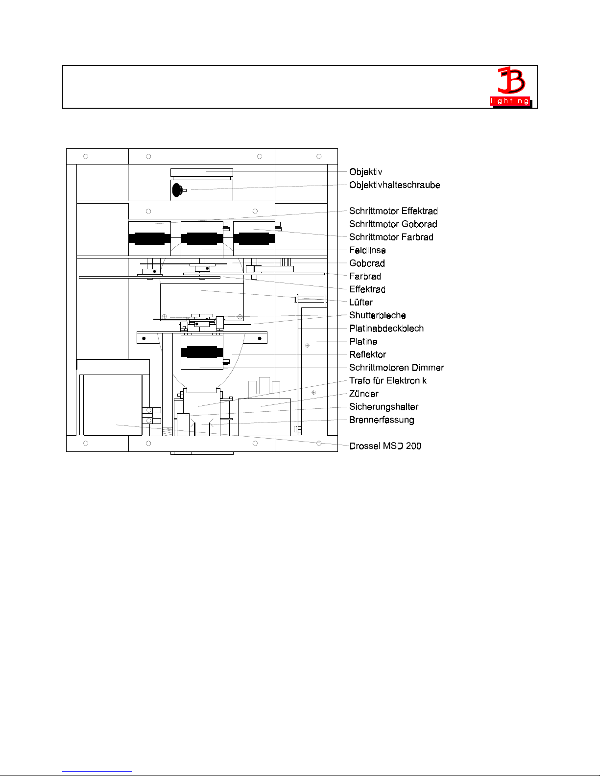
Abbildung Varycolor 2000
Page 10
Varycolor 2000
- 10 -
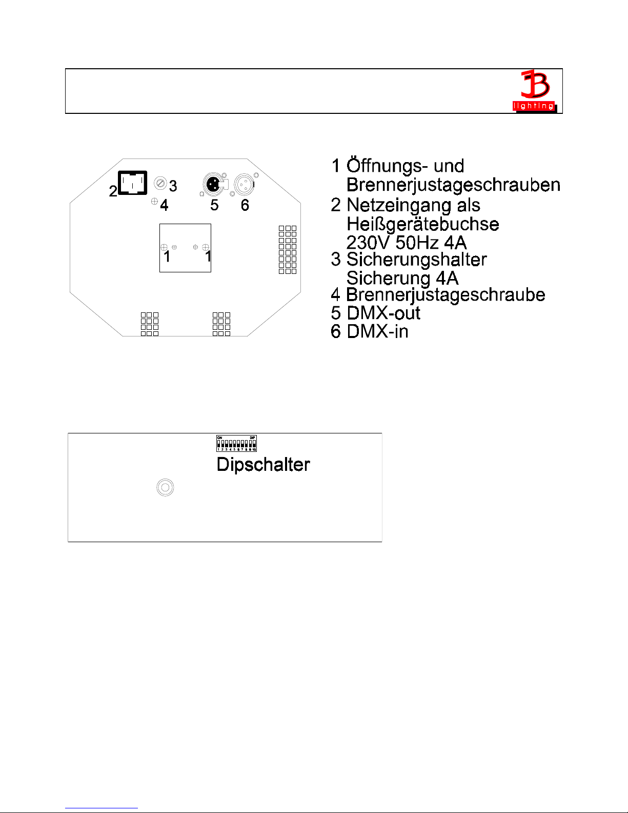
Rückansicht Varycolor 2000
Lage des Dipschalters (rechtes Seitenteil)
Page 11

Varycolor 2000
- 11 -
Auspacken der Varycolor 2000 - Anlage
Vor Ihnen befindet sich Ihre komplette Varycolor 2000 - Anlage
Entnehmen Sie zuerst alle Teile aus den Kartons. Prüfen Sie, ob alle Teile in der Lieferung
enthalten sind.
•
Varycolor 2000
•
Heißgerätekabel ohne Schuko-Stecker
•
diese Anleitung
Sollten Sie einen Transportschaden feststellen, teilen Sie diesen bitte sofort dem
Transportunternehmen bzw. Ihrem Händler mit.
Die Verpackung Ihrer Varycolor wird -wenn möglich- aus Umweltgründen mehrfach verwendet.
Sie erhalten bei Rückgabe der Verpackungen eine Teilgutschrift.
Bitte machen Sie von der Rückgabe im Sinne unserer Umwelt Gebrauch. Wir bitten Sie aus
diesem Grunde auch um Verständnis, falls Sie evtl. eine gebrauchte Verpackung bzw. Inlay
erhalten sollten.
Page 12
Varycolor 2000
- 12 -
Brenner einsetzen/auswechseln
HINWEIS: Vor dem Öffnen Netzstecker ziehen!!
Schrauben Sie den Brennerschacht an der Rückseite des Varycolor mit
einem passenden Kreuzschlitzschraubendreher auf (Siehe Skizze S. 9).
Setzen Sie nun den Brenner in Ihren Varycolor ein. Anschließend
schrauben Sie den Brennerschacht wieder zu.
Achtung:
Berühren Sie niemals beim 200 MSD den Glaskörper selbst!
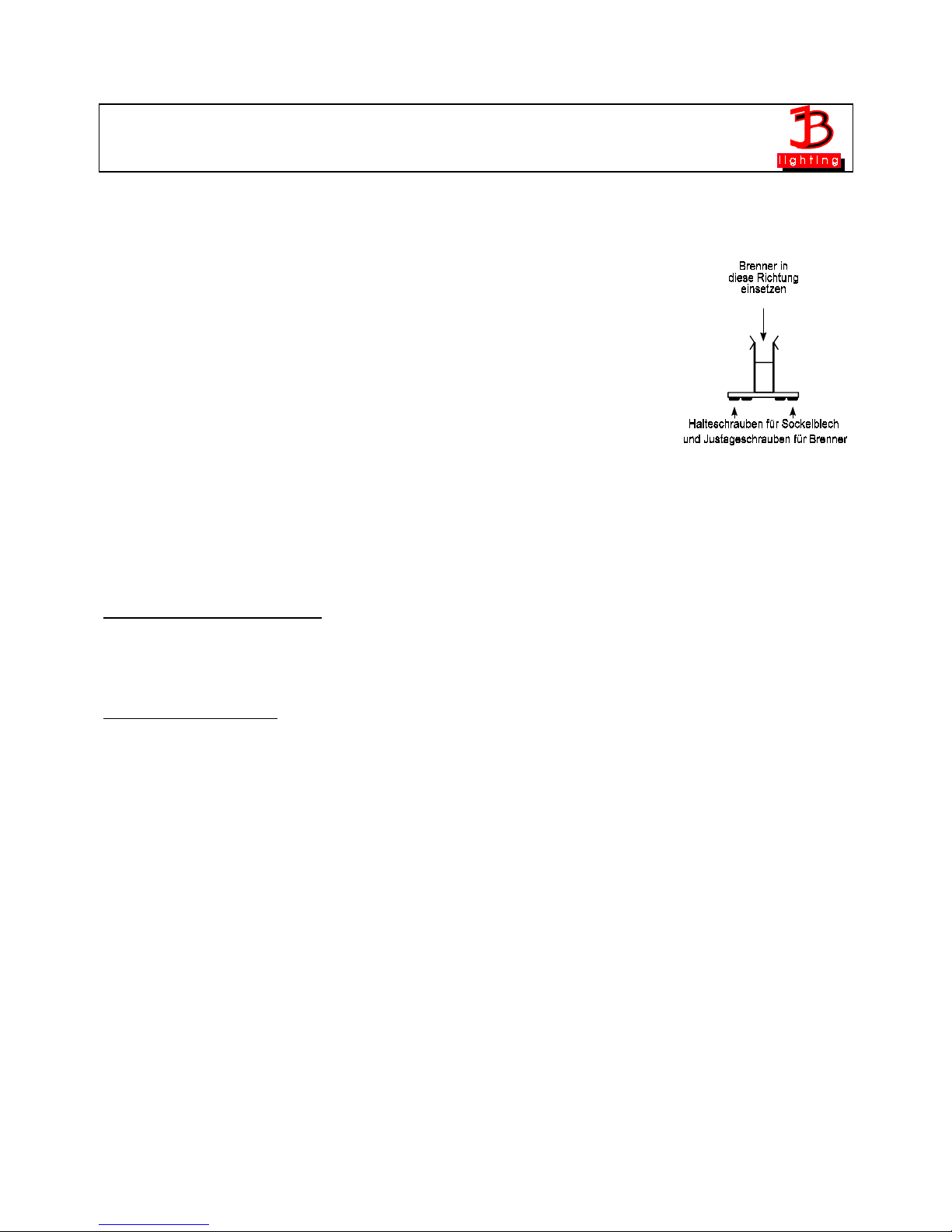
Brennerjustierung
Zur Justierung des Brenners verwenden Sie die zwei Schrauben Nr. 1
mit welchen der Brennerschacht festgeschraubt ist und die silberne
Schrauben Nr. 4 (Siehe Skizze Seite 9). Lösen Sie die Halteschrauben für das Sockelblech
und versuchen Sie nun hiermit den Brenner in die Mitte des Reflektors zu bringen. Anschließen
drehen Sie an der Schraube Nr. 4 (Siehe Skizze Seite 9) so lang bis der Brenner am Hellsten
erscheint und die Ausleuchtung am Besten ist.
Inbetriebnahme der Anlage
1. Varycolor 2000 aufstellen
Stellen Sie Ihren Varycolor 2000 entweder auf eine feste Unterlage oder hängen Sie den
Varycolor 2000 an dem dafür vorgesehen Bügel auf. Achten Sie auf jeden Fall darauf, daß
sämtliche Lüftungsschlitze frei sind.
2. Varycolor verkabeln
Die Verkabelung führen Sie wie folgt durch:
Verbinden Sie den Ausgang Ihres DMX-Controllers mit dem ersten Varycolor 2000 (Controller
DMX-Out; Varycolor 2000 DMX-In) mit Hilfe eines 3poligen XLR-Kabels. Stellen Sie nun mit
Hilfe weiterer 3pol-XLR Kabel die Verbindung zwischen den Varycolor her. Achten Sie darauf,
daß beim letzten Farbwechsler im DMX-Out ein Endstecker (XLR-Stecker mit einem
Widerstand von 100 Ohm zwischen Pin 2 und 3) steckt.
Page 13
Varycolor 2000
- 13 -
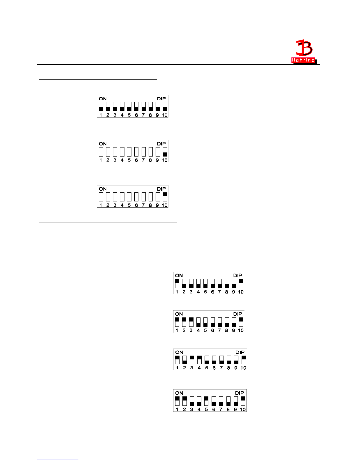
3. Grundeinstellungen am DIP-Schalters
Alle DIP-Schalter "OFF": Testmodus (alle Funktionen des Varycolor 2000 laufen durch)
DIP-Schalter 10 "OFF" Reset über DMX aus
DIP-Schalter 10 "ON" Reset über DMX on (DMX-Wert 255 auf Gobokanal)
Einstellen der DMX-Adressen am DIP-Schalter
Ihr Varycolor verwendet 6 DMX-Kanäle, deshalb müssen Sie die DMX-Adressen in 6er-
Schritten eingestellt werden.
Varycolor Nr. DMX-Adresse Schaltereinstellung
1 1
2 7
3 13
4 19
Page 14
Varycolor 2000
- 14 -
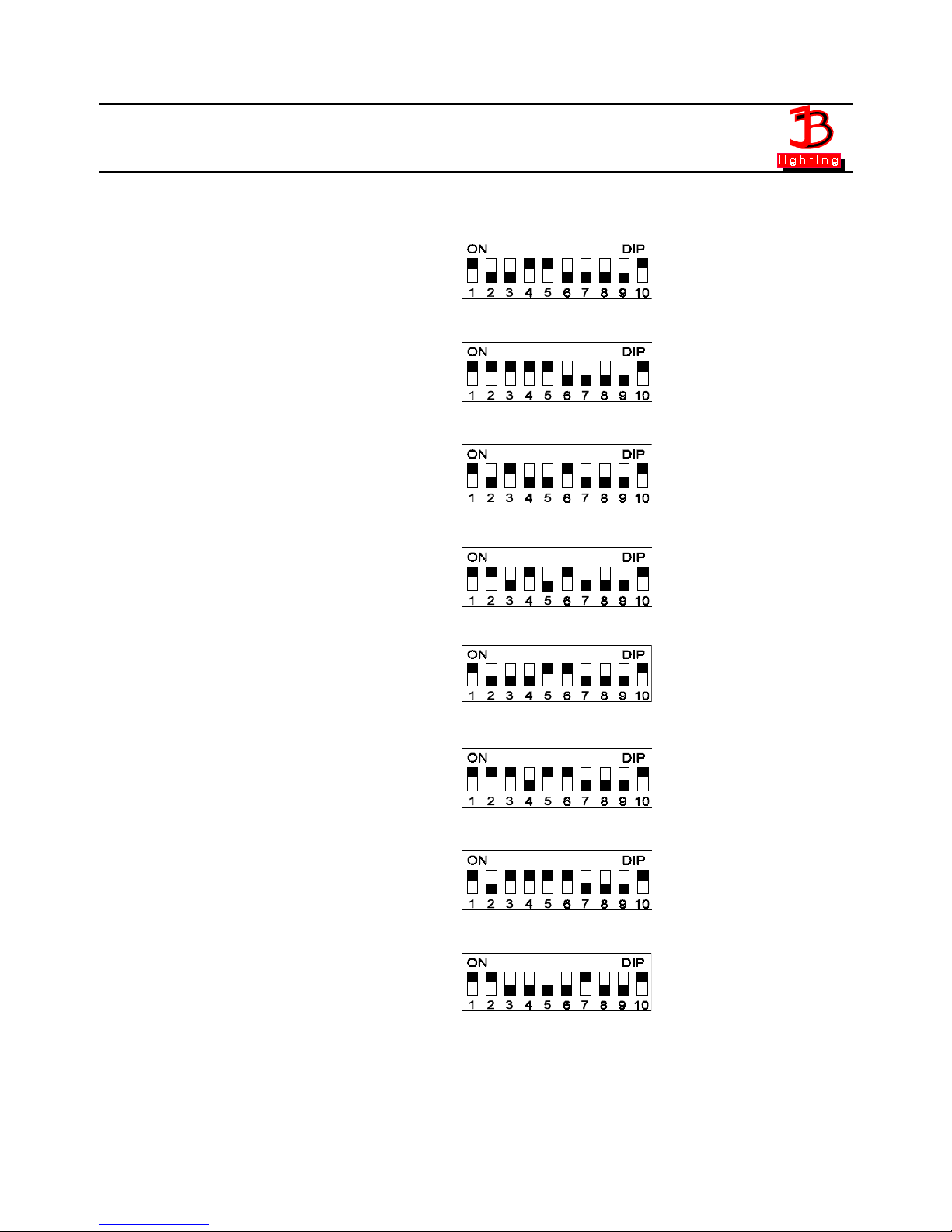
Varycolor Nr. DMX-Adresse Schaltereinstellung
5 25
6 31
7 37
8 43
9 49
10 55
11 61
12 67
Page 15
Varycolor 2000
- 15 -
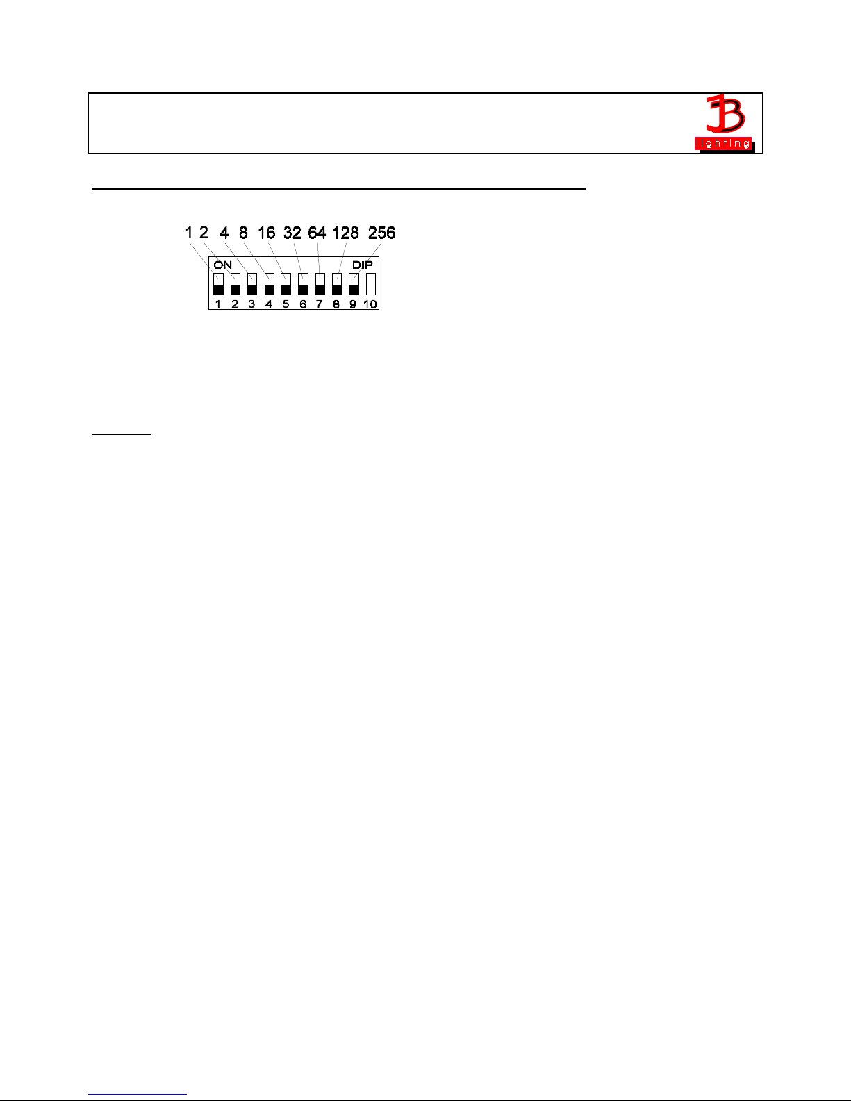
Bestimmung der DIP-Schaltereinstellung für bestimmte DMX-Adressen
Die einzelnen DIP-Schalter entsprechen den oben angezeigten Werten. Soll nun eine
bestimmte DMX-Adresse eingestellt werden, so muß diese nur aus den einzelnen Werten
zusammengezählt werden.(Immer größtmögliche Werte verwenden)
Beispiel: DMX-Adresse "45"
32 + 8 + 4 + 1 = 45
SW6
SW4 SW3 SW1
on
on
on on
Die restlichen DIP-Schalter
SW9 SW8 SW7 SW5 SW2
bleiben auf "
OFF
".
Page 16

Varycolor 2000
- 16 -
B Serviceanleitung
Fehlerbehebung
Fehler Behebung des Problems
Das Gerät arbeitet überhaupt
nicht
4 Ampere-Sicherung an der
Rückseite des Gerätes
austauschen
Der Brenner des Gerätes
leuchtet nicht, aber die
Elektronik funktioniert,
d.h. die Motoren funktionieren
1. Der Brenner ist defekt, der
Brenner muß getauscht werden
2. Temperatursicherung im Inner
e
des Gerätes austauschen
(Achtung: Nur mit Löterfahrung
durchführen!!)
DMX-Eingang funktioniert nichtDIP-Schaltereinstellung
kontrollieren
Austauschen der Temperatursicherung
Führen Sie diese Arbeit nur durch, wenn Sie Löterfahrung und folgende Werkzeuge haben:
Lötkolben, Ohmmeter.
Achtung:
Vor dem Öffnen des Gerätes Netzstecker ziehen!
Öffnen Sie an der Oberseite des Varycolor 2000 die zehn Kreuzschlitzschrauben. und heben Sie
den Deckel ab. Sie finden die Temperatursicherung in der hinteren Hälfte des Varycolor 2000. Die
Temperatursicherung ist durch einen (weißen) Silikonschlauch geschützt und mit einem Ende
in der Drossel festgeschraubt. Schrauben Sie nun die Temperatursicherung von der Klemme an
der Drossel los und entfernen Sie den Silikonschlauch. Jetzt können Sie mit einem Lötkolben die
Temperatursicherung von der Leitung ablöten und die neue Temperatursicherung mit dem kurzen
Ende wieder an der Leitung anlöten. Jetzt müssen Sie mit einem Ohmmeter die
Temperatursicherung auf Durchgang prüfen, denn sie könnte durch die Lötarbeit zerstört worden
sein. Schieben Sie nun den Silikonschlauch wieder über die Temperatursichung, und befestigen
diesen wieder mit einem Kabelband.
Achtung:
Die Temperatursicherung ist spannungsführend. Sie muß komplett mit dem
Silikonschlauch abgedeckt sein.
Schrauben Sie nun das andere Ende der Temperatursicherung wieder an der Klemme der
Drossel fest. Schließen Sie nun das Gehäuse und testen Sie Ihren Varycolor 2000.
Page 17

Varycolor 2000
- 17 -
Regelmäßige Wartungsarbeiten
Sie sollten folgende Arbeiten alle 1 - 2 Monate durchführen. Sie erhöhen somit die
Lebensdauer Ihres Varycolor um viele Jahre
Achtung: Vor dem Öffnen des Gerätes Netzstecker ziehen!
Öffnen Sie das Gehäuse, in dem Sie die zehn Kreuzschlitzschrauben an der Oberseite des
Varycolor herausdrehen.
1. Reinigung aller optischen Teile
Sie sollten in regelmäßigen Abständen die optischen Teile des Varycolor 2000 reinigen um
wieder die maximale Helligkeit des Farbwechslers herzustellen. Nachdem Sie das Gehäuse wie
oben beschrieben geöffnet haben nehmen Sie ein fusselfreies Tuch und etwas
Fensterputzmittel und reinigen Sie die Filter auf dem Farb- bzw. Effektrad.
Anschließend reinigen Sie noch die Feldlinse, welche sich auf einem Zusatzblech auf dem
Motorenhalteblech befindet. Um das Objektiv leichter reinigen zu können lösen Sie die
Objektivhalteschraube und entnehmen das Objektiv. Nun können Sie es leicht innen und außen
reinigen. Setzen Sie anschließend das Objektiv wieder ein. Vergessen Sie nicht, die
Objektivhalteschraube wieder anzuziehen.
2. Überprüfen der Lüftung
Prüfen Sie alle Lüftungsschlitze und den Lüfter auf Sauberkeit, Gegebenenfalls reinigen Sie
den Lüfter und die Lüftungsschlitze mit einem Pinsel oder Sie saugen den Schmutz mit einem
Staubsauger ab.
Bei Schäden die auf Verschmutzung zurückgeführt werden können
erlischt die Garantie!!
Nun können Sie Ihren Varycolor wieder schließen
Page 18

Varycolor 2000
- 18 -
Allgemeine Informationen zum DMX512-Protokoll
Das DMX512-Protokoll ist in 512 Adressen eingeteilt. Über diese 512 Adressen kann frei vefügt
werden. Um nun verschiedene Geräte an einen DMX-Controller anschließen zu können, muß
zuerst die Anzahl der DMX-Kanäle für jedes Gerät ermittelt werden. Die Kanalbelegung eines
Farbwechslers könnte beispielsweise wie folgt aussehen.
Kanal 1 frei
Kanal 2 frei
Kanal 3 Gobo
Kanal 4 Farbe
Kanal 5 Shutter / Dimmer
Kanal 6 Effekt
Damit nun nicht jedes angeschlossene DMX-Gerät die gleichen Funktionen ausführt werden die
Geräte hintereinander adressiert; d.h. das Erste verwendet die ersten sechs Adressen (gilt für
ein Gerät mit sechs Kanälen) und das Zweite verwendet die nächsten sechs Adressen (Gerät
mit sechs Kanälen) der 512 DMX-Adressen (Beispiel Varycolor siehe Seite13)
Kanalbelegung Varycolor 2000
1. Varycolor 2000 6 Kanäle
Kanal 1 frei
Kanal 2 frei
Kanal 3 Gobo
Kanal 4 Farbe
Kanal 5 Shutter / Dimmer
Kanal 6 Effekt (JB DMX-Controller Feature IRIS)
Kanal 1 = frei
Kanal 2 = frei
Kanal 3 = Gobo
Gobo 0 (Flood) DMX 000 - 031
Gobo 1 (Beam 1) DMX 032 - 063
Gobo 2 (Beam 2) DMX 064 - 095
Gobo 3 (Beam 3) DMX 096 - 127
Gobo 4 (Beam 4) DMX 128 - 159
Gobo 5 (Blackout) DMX 160 - 255
bei DIP-Schalter 10 on
Gobo 5 (Blackout) DMX 160 - 254
Reset über DMX DMX 255
Page 19

Varycolor 2000
- 19 -
Kanal 4 = Farbe
Farbe01 DMX 000 - 003
Farbe02 DMX 004 - 007
Farbe03 DMX 008 - 011
Farbe04 DMX 012 - 015
Farbe05 DMX 016 - 019
Farbe06 DMX 020 - 023
Farbe07 DMX 024 - 027
Farbe08 DMX 028 - 031
Farbe09 DMX 032 - 035
Farbe10 DMX 036 - 039
Farbe11 DMX 040 - 043
Farbe12 DMX 044 - 047
Farbe13 DMX 048 - 051
Farbe14 DMX 052 - 055
Farbe15 DMX 056 - 059
Farbe16 DMX 060 - 063
Farbe17 DMX 064 - 067
Farbe18 DMX 068 - 071
Farbe19 DMX 072 - 075
Farbe20 DMX 076 - 079
Farbe21 DMX 080 - 083
Farbe22 DMX 084 - 087
Farbe23 DMX 088 - 091
Farbe24 DMX 092 - 127
Farbradrotation langsam DMX 128 Farbradrotation schnell DMX - 255
Kanal 5 = Shutter / Dimmer
Dimmer / Shutter zu DMX 000
Dimmer (linear) DMX 001 - 127
Dimmer / Shutter auf DMX 128 - 139
Shuttereffekt linear langsam nach schnell DMX 140 - 243
Dimmer / Shutter auf DMX 244 - 255
Kanal 6 = Effekt
Effekt01 DMX 000 - 031
Effekt02 DMX 032 - 063
Effekt03 DMX 064 - 255
Page 20

Varycolor 2000
- 20 -
Belegung DMX-IN / DMX-OUT
Lage der Buchsen siehe Seite 10
DMX-IN DMX-OUT
Pin1: Ground schwarz Pin1: Ground schwarz
Pin2: DMX- beige Pin2: DMX- beige
Pin3: DMX+ rot Pin3: DMX+ rot
Technische Daten
Ausmaße: Höhe 29,5 cm
Breite 26 cm
Tiefe 21 cm (mit Bügel 29 cm)
Gewicht: ca. 11kg
Leistungsaufnahme: ca. 920W
Netzspannung: 230V 50Hz 4A
Brenner: Philips MSD 200 Entladungslampe
Farbtemperatur 5500 K
13700 Lumen
Sicherung 1: 4,0 Ampere träge (230V-Verkabelung)
Sicherung 2: Temperatursicherung 98°C
Page 21

Varycolor 2000
- 21 -
Stromlaufplan Varycolor 2000
Page 22

Varycolor 2000
- 22 -
Belegung der Stecker und Jumper
Skizze Platinenstecker
Pin/Farbe Pin/Farbe Pin/Farbe Pin/Farbe Stecker
Dimmer1 1 orange 2 blau 3 rot 4 gelb JP8
Dimmer2 1 orange 2 blau 3 rot 4 gelb JP9
Farbe1 1 orange 2 blau 3 rot 4 gelb JP4
Effekt 1 orange 2 blau 3 rot 4 gelb JP3
Gobo 1 orange 2 blau 3 rot 4 gelb JP5
Lüfter 1 frei 2 frei 3 schwarz 4 rot JP7
AC-IN 1 schwarz 2 schwarz JP6
DMX-IN/OUT 1 grün 2 rot-weiß 3 beige 4 schwarz JP1
Epromwechsel / Software Update
Um das Eprom zu wechseln gehen Sie wie folgt vor:
Öffnen Sie den Deckel des Varycolor 2000. Anschließend entfernen Sie das rechte Seitenteil
mit der Platine. Entfernen Sie nun die Platinenabdeckung, indem Sie die vier
Kreuzschlitzschrauben entfernen (Siehe Skizze Seite 9). Wenn Sie nun die Platine mit dem
Bestückungsplan vergleichen können Sie auf der unteren rechten Seite das Eprom erkennen
(IC U2). Hebeln Sie das alte Eprom vorsichtig aus der Fassung und tauschen es gegen das
neue Eprom aus.
Achtung:
Achten Sie auf die Polarität des Eproms!!
(Die Einbuchtung am Eprom muß in die gleiche
Richtung zeigen wie die Einbuchtung an der IC-Fassung)
Bauen Sie nun Ihren Varycolor 2000 wieder zusammen. Stecken Sie nun Ihren Varycolor ein
und testen Sie bitte alle Funktionen.
Page 23

Varycolor 2000
- 23 -
Stückliste Platine Varycolor 2000
R1 10M 0,6W
R2 22k 0,6W
R3 9*10K SIP 0,25W
R4 10K 0,6W
R5 10K 0,6W
R6 10K 0,6W
R7 1,5R 1W
R8 1,5R 1W
R9 15K 1W
R10 1K 0,6W
R11 1K 0,6W
R12 1,2R 1W
R13 1,2R 1W
R14 1,5R 1W
R15 1,5R 1W
R16 240R 0,6W
R17 768R 0,6W
R18 8,2R 1W
R19 2,2K 0,6W
R20 15K 0,6W
R21 1K 0,6W
R22 1K 0,6W
R23 0,68R 1W
R24 0,68R 1W
R25 1K 0,6W
R26 1K 0,6W
R27 0,68R 1W
R28 0,68R 1W
R29 15K 0,6W
C1 18pF
C2 18pF
C3 nicht bestückt
C4 100nF
C5 100nF
C6 nicht bestückt
C7 4,7uF
C8 220nF
C9 nicht bestückt
C10 nicht bestückt
C11 2,2nF
C12 820pF
C13 820pF
C15 nicht bestückt
Page 24

Varycolor 2000
- 24 -
C16 3,3nF
C17 220nF
C18 nicht bestückt
C19 47uF
C20 47uf
C21 47uF
C22 nicht bestückt
C23 2,2nF
C24 100nF
C25 470uF
C26 100nF
C27 4700uF
C28 100nF
C29 820pF
C30 820pF
C31 nicht bestückt
C32 nicht bestückt
C33 3,3nF
C34 220nF
C36 47uF
C37 820pF
C38 820pF
C39 220nF
C40 47uF
C41 3,3nF
JP1 Header4 DMX IN JP2 Header2 Test
JP3 Header4 Effekt JP4 Header4 Farbe
JP5 Header4 Gobo JP6 2*AMP AC-In 11V
JP7 Header4 Lüfter JP8 Header4 Dimmer1
JP9 Header4 Dimmer2
D1 Bridge 4A D2 Spannungsreferenz 2,5V LM336
U1 M68HC11F1FN
U2 Eprom 27C256
U3 AM26LS32 IC DMX-IN
U4 TCA3727 Treiber Effektrad-Motor
U5 PBM3960 Treiber für U6
U6 PBL3771 Treiber für Farbrad-Motor
U7 T CA3727 Treiber für Goborad-Motor
U8 LM317T Regelung 5V
U9 PBM 3960 Treiber für U10/U11
U10 PBL3771 Treiber für Dimmer-Motor 1
U11 PBL3771 Treiber für Dimmer-Motor 1
Page 25

Varycolor 2000
- 25 -
Y1 Quarz 16MHz
S1 SW DIP-10 DIP-Schalter NR. 1
Bestückungsplan Varycolor
Page 26

Varycolor 2000
- 26 -
Page 27

Varycolor 2000
- 27 -
Operating instructions
Varycolor 2000
Made in Germany by JB-lighting
Version 2.00
Page 28

Varycolor 2000
- 28 -
Page 29

Varycolor 2000
- 29 -
Preface
You decided to buy a Varycolor 2000 by JB-lighting.
Thanks a lot for your confidence in our products.
With the Varycolor 2000 you have many facilities to realize desired effects. First of all read
through the operating instructions very calmly, because they contain informations that will
guarantee an entire use of your Varycolor.
We wish you lots of fun and successful shows.
JB-lighting
Page 30

Varycolor 2000
- 30 -
Index
A Operating Instructions
Slip
Preface 29
Index 30
Illustration of Varycolor 2000 31
Backview and Position of the DIP-Switch 32
Unpacking of Varycolor 2000 Equipment 33
How to put in/ exchange the Bulb 33
Adjustment of the Bulb 33
Starting the Equipment 34
Basic Adjustments at the DIP-Switch 34
Adjustment DMX-Addresses 35
Adjustment of a Definite DMX-Address 37
B Service Instructions
Repair of Defects 38
Exchange of Overheat Protection 38
Regular Maintenance Performances 39
General Informations about the DMX-Record 40
Occupation of Channels for Varycolor 2000 40
Occupation DMX-IN DMX-OUT 42
Technical Data 42
Plan of Current Circuits for Varycolor 2000 43
Occupation of Connector Rows and Jumper 44
Changing of Eprom/ Software Update 44
List of Pieces for Electronic Card of Varycolor 2000 45
Plan of Electronic Part for Electronic Card 47
Plan of Current Circuits for Electronic Card 48
Page 31

Varycolor 2000
- 31 -
Illustration of Varycolor 2000
Page 32

Varycolor 2000
- 32 -
Back View of Varycolor 2000
Position of DIP-Switch (Right Side-Piece)
Page 33

Varycolor 2000
- 33 -
Unpacking of Varycolor 2000 Equipment
Before you, you find the complete Varycolor 2000 equipment.
First of all take all parts from the carton. Check, if the delivery contains all parts.
•
Varycolor 2000
•
Powercord without plug
•
these operating instructions
Should you notice a damage through transportation, please immediately inform the carriers
respectively your dealer.
The packing of Varycolors will be used several times- if possible- because of conservation. In
case of returning packin gs you will get a part-credit.
Please make use of the return of packings within the meaning of our environment.
For this reason we ask for your comprehension, also in case of getting a used packing,
respectively inlay from us.
Put in/ Exchange of the Bulb
Warning
: Before opening pull out mains plug!
Unscrew the bulb shaft at the back of the Varycolor with a suitable screwdriver (compare to sketch page 31). Now put the bulb into your Varycolor,
subsequently screw the bulb shaft into the starting position.
Warning
:
Never
touch the glass of bulb of the 200 MSD itself!
Adjustment of the Bulb
For adjusting the bulb please use the two screws marked as No. 1, with which the bulb shaft is
screwed tightly and the screws of silver marked as No. 4 (compare to sketch p. 31). Detach the
screws fixing the base sheet and try now with this sheet to place the bulb in the middle of the
reflector. Next turn the screw marked as No. 4 (compare to sketch p. 31), as long until the bulb
appears in brightest light and the illumination come up to it's optimum.
Page 34

Varycolor 2000
- 34 -
Starting the Equipment
1. Set up of Varycolor 2000
Either set up your Varycolor 2000 on a steady base or hang up your Varycolor 2000 from the
bow assigned for. Take care that in any case all slits for ventilation are clear.
2. Cabling of Varycolor
Carry-out the cabling as follows:
Connect the output of your DMX-controller with the first Varycolor 2000 (controller DMX-out;
Varycolor DMX-in) with the aid of a 3pole XLR-cabel. Now establish the connection between
Varycolor with the aid of further 3pole XLR-cables. Make sure that in DMX-out of the last
Varycolor there is a resistor (XLR-plug with a resistance of 100 Ohm between pin 2 and pin 3)
plugged into.
3. Basic Adjustments at DIP-Switches
All DIP-switches "OFF": test mode (all functions of Varycolor 2000 are ran through)
DIP-switch 10 "OFF" 4 DMX-RESET off
DIP-switch 10 "ON" 6 DMX-RESET on
Page 35

Varycolor 2000
- 35 -
Adjustment of DMX-Addresses at the DIP-Switch
Your Varycolor 2000 is working in a 6 channel drive mode. The DIP-switch adjustment has to
follow in 6 steps.
Varycolor No. DMX-address DIP-switch position
1 1
2 7
3 13
4 19
5 25
6 31
Page 36

Varycolor 2000
- 36 -
Varycolor No. DMX-address DIP-switch position
7 37
8 43
9 49
10 55
11 61
12 67
Page 37

Varycolor 2000
- 37 -
Definition of DIP-Switch Positions for Defined DMX-Addresses
Every single DIP-switch responds to the above designated figures. If you would like to adjust a
defined DMX-address, you have to add up the single figures to get it. (Always use the highest
figures as possible)
For example: DMX-address "45"
32 + 8 + 4 + 1 = 45
SW6
SW4 SW3 SW1
on
on
on on
All remaining DIP-switches
SW9 SW8 SW7 SW5 SW2
stay in position "OFF".
Page 38

Varycolor 2000
- 38 -
B Service Instructions
Repair of Defects
Defect Reparation
The appliance does not work
at all
Exchange 4Ampere fuse at
the back of the appliance
The bulb of the appliance
does not shine, but
electronics are working, i.e.
motors are working
1. The bulb is defect, you
have to change it
2. Change the overheat
protection inside the appliance
(Warning: Has to be repaired
only by persons with
experience in soldering!)
DMX-input does not work Control DIP-switch position
Exchange of overheat protection
Carrying-out of this work should be done only with experience in soldering and the following
tools: soldering-iron
Warning: Before opening the appliance pull out mains plug!
Loosen the ten screws on top of the Varycolor 2000 and lift the lid. In the back part of the
Varycolor 2000 you find the overheat protection. This overheat protection is protected by a
white silicon tube and with one end it is fixed in the ballast. Now loosen the overheat protection
from the clamp at the ballast and remove the silicon tube. Subsequently you can solder the
overheat protection from the lead with a soldering-iron, then solder a new overheat protection
with it's short end to the lead. Now you have to check if the overheat protection works, because
it could have been damaged by soldering. Then cover the overheat protection again with the
silicon tube and fix the tube.
Warning:
The overheat protection is under voltage, it has to be
completely covered with the silicon tube!
Now screw the opposite end of the overheat protection again at the clamp of the (Drossel).
Close the casing now and test your Varycolor 2000.
Page 39

Varycolor 2000
- 39 -
Regular Maintenance Performances
Carry-out the following perf ormance s every 1 or 2 mont hs. There by you will increase sevice life
of your Varycolor 2000 for many years.
Warning: Before opening the appliance pull out mains plug!
Open the casing by turning out the ten screws at the top of your Varycolor.
1. Cleaning of all optical parts
You should clean the optical parts of your Varycolor 2000 periodically to restore maximum
brightness of the varycolor. After having opened the casing as explained above, take a fuzzfree rag and a detergent for windows and clean the dichroic filters on the colour wheel and the
effectwheel.
Subsequently clean the aspherical lense, which is placed on an additional sheet on the holding
sheet for the motor. In order to clean the lens easily, loosen the screw which fixes the lens and
remove the lens. Now it is easy to clean from the outside and the inside. Put the lens at it's
position again. Do not forget to tighten the screw which fixes the lens.
2. Check of ventilation
Check, if the ventilator and all ventilation shafts are clean. If need be, clean the ventilator and
the ventilation shafts with a brush or use a vacuum cleaner to remove dust.
Guarantee shall not apply to damages caused through pollution!
Now close the casing of your Varycolor 2000.
Page 40

Varycolor 2000
- 40 -
General Informations about DMX512 Record
DMX512 record is devided in 512 addresses. You have 512 addresses to your disposal. To be
able to connect different appliances with a DMX-controller, it is necessary to determine the
number of DMX-channels for every appliance. The occupation of channels of a varycolor could
be like that for example:
channel 1 free
channel 2 free
channel 3 gobowheel
channel 4 colourwheel
channel 5 shutter/dimmer
channel 6 effectwheel
In order that not every connected DMX-appliance performs same functions, the appliances are
addressed in series; i.e. for the first appliance the first 6 addresses are used (be right for an
appliance with 6 channels), for the second one the next 6 addresses (appliance with four
channels) of all the DMX-addresses are used (see for example Varycolor p.35)
Occupation of channels for varycolor 2000
Channel 1 = free
Channel 2 = free
Channel 3 = gobowheel
Channel 4 = colourwheel
Channel 5 = shutter / dimmer
Channel 6 = effectwheel
channel 01 = free
channel 02 = free
channel 03 = gobowheel
gobo 01 DMX 000 - 031
gobo 02 DMX 032 - 063
gobo 03 DMX 064 - 095
gobo 04 DMX 096 - 127
gobo 05 DMX 128 - 159
gobo 06 DMX 160 - 255
if at DIP-switch No.1 switch 10 is "ON"
gobo 06 DMX 160 - 254
Reset DMX 255
channel 04 = colourwheel
colour 01 (weiß) DMX 000 - 003
colour 02 DMX 004 - 007
Page 41

Varycolor 2000
- 41 -
colour 03 DMX 008 - 011
colour 04 DMX 012 - 015
colour 05 DMX 016 - 019
colour 06 DMX 020 - 023
colour 07 DMX 024 - 027
colour 08 DMX 028 - 031
colour 09 DMX 032 - 035
colour 10 DMX 036 - 039
colour 11 DMX 040 - 043
colour 12 DMX 044 - 047
colour 13 DMX 048 - 051
colour 14 DMX 052 - 055
colour 15 DMX 056 - 059
colour 16 DMX 060 - 063
colour 17 DMX 064 - 067
colour 18 DMX 068 - 071
colour 19 DMX 072 - 075
colour 20 DMX 076 - 079
colour 21 DMX 080 - 083
colour 22 DMX 084 - 087
colour 23 DMX 088 - 091
colour 24 DMX 092 - 127
colour wheel rotation speed 1 (slow) DMX 128 colour wheel rotation speed 7 (fast) DMX 255
channel 05 = dimmer / shutter
dimmer shutter closed --> blackout (BO) DMX 0
dimmer: you can perceive some light DMX 19
dimmer DMX 20 - 127
dimmer completely open DMX 128 - 137
shutter immediatelly closed DMX 138 - 139
shutter sequence slow DMX 140 shutter sequence fast DMX - 243
shutter immediatelly open DMX 244 - 255
channel 06 = effectwheel
open DMX 000 - 063
artificial light filter DMX 064 - 127
daylight filter DMX 128 - 255
Page 42

Varycolor 2000
- 42 -
Occupation DMX-IN/ DMX-OUT
Position of sockets see page 32
DMX-IN
Pin 1: Ground black
Pin 2: DMX- beige
Pin 3: DMX+ red
Technical Data
Measurements: height 29,5cm
width 26cm
depth 21cm(with bow 29 cm)
Weight: 11kg
Power consumption: 950VA
Mains voltage: 230V 50Hz 4A
Bulb: Philips MSD 200 discharge lamp
colour temperature 550K
13700 Lumen
Fuse 1: 4,0 Ampere inert (230V-cabeling)
Fuse 2: temperature fuse 98°C
Page 43

Varycolor 2000
- 43 -
Plan of current circuits for Varycolor 2000
Page 44

Varycolor 2000
- 44 -
Occupation of connectors and jumpers
sketch connector
Pin/colour Pin/colour Pin/colour Pin/colour Stecker
dimmer1 1 orange 2 blue 3 red 4 yellow JP8
dimmer2 1 orange 2 blue 3 red 4 yellow JP9
colour 1 orange 2 blue 3 red 4 yellow JP4
effect 1 orange 2 blue 3 red 4 yellow JP3
gobo 1 orange 2 blue 3 red 4 yellow JP5
ventilator 1 f ree 2 free 3 black 4 red JP7
AC-IN 1 black 2 black JP6
DMX-IN/OUT 1 green 2 red-white 3 beige 4 black JP1
Change of Eprom/ Software Update
To change the Eprom proceed as follows:
Open the lid of Varycolor 2000. Now remove the right side-piece with the electronic card.
Remove the cover sheet for the electronic card by taking out the 4 screws (see sketch page
31). By comparing the electronic card with the plan of electronic parts (see sketch page 47),
you can see the Eprom at the bottom of the right side (IC U2). Carefully lever the used Eprom
from the holder and exchange it for a new one.
Direction:
Pay attention to the polarity of the Eprom!
(The inlet of the Eprom has to point to the same direction
as the inlet of the IC-holder.)
Now assemble your Varycolor 2000. Plug in your Varycolor and please test all functions.
Page 45

Varycolor 2000
- 45 -
List of pieces for electronic card of varycolor 2000
R1 10M 0,6W
R2 22k 0,6W
R3 9*10K SIP 0,25W
R4 10K 0,6W
R5 10K 0,6W
R6 10K 0,6W
R7 1,5R 1W
R8 1,5R 1W
R9 15K 1W
R10 1K 0,6W
R11 1K 0,6W
R12 1,2R 1W
R13 1,2R 1W
R14 1,5R 1W
R15 1,5R 1W
R16 240R 0,6W
R17 768R 0,6W
R18 8,2R 1W
R19 2,2K 0,6W
R20 15K 0,6W
R21 1K 0,6W
R22 1K 0,6W
R23 0,68R 1W
R24 0,68R 1W
R25 1K 0,6W
R26 1K 0,6W
R27 0,68R 1W
R28 0,68R 1W
R29 15K 0,6W
C1 18pF
C2 18pF
C3 not occupied
C4 100nF
C5 100nF
C6 not occupied
C7 4,7uF
C8 220nF
C9 not occupied
C10 not occupied
C11 2,2nF
C12 820pF
C13 820pF
C14 not occupied
Page 46

Varycolor 2000
- 46 -
C16 3,3nF
C17 220nF
C18 not occupied
C19 47uF
C20 47uf
C21 47uF
C22 not occupied
C23 2,2nF
C24 100nF
C25 470uF
C26 100nF
C27 4700uF
C28 100nF
C29 820pF
C30 820pF
C31 not occupied
C32 not occupied
C33 3,3nF
C34 220nF
C36 47uF
C37 820pF
C38 820pF
C39 220nF
C40 47uF
C41 3,3nF
JP1 Header4 DMX IN JP2 Header2 for test
JP3 Header4 effect JP4 Header4 color
JP5 Header4 gobowheel JP6 2*AMP AC-In 11V
JP7 Header4 fan JP8 Header4 dimmer1
JP9 Header4 dimmer2
D1 Bridge 4A D2 Referenz 2,5V LM336
U1 M68HC11F1FN
U2 Eprom 27C256
U3 AM26LS32 IC DMX-IN
U4 TCA3727 driver for Effektrad-Motor
U5 PBM3960 driver for U6
U6 PBL3771 driver for colorwheel
U7 T CA3727 driver for Gobowheel
U8 LM317T stabilisation 5V
U9 PBM 3960 driver for U10/U11
U10 PBL3771 driver for dimmermotor 1
U11 PBL3771 driver for dimmermotor 2
Page 47

Varycolor 2000
- 47 -
Y1 Quarz 16MHz
S1 SW DIP-10 DIP-Switch
Plan of electronic parts for electronic card
of Varycolor 2000
Page 48

Varycolor 2000
- 48 -
 Loading...