

Page 1
Bedienungsanleitung | Operating Instructions
10
Version 1.6
Software >= 1.23
Page 2

- 02 -
10
Page 3

10
Inhalt / Content
1. Maße und Produktübersicht . . . . . . . . . . . . . . . . . . . . . . . . . . . . . . . . . . . . . . . . . . . . . . . .04
2. Einleitung . . . . . . . . . . . . . . . . . . . . . . . . . . . . . . . . . . . . . . . . . . . . . . . . . . . . . . . . . . . . . . .05
2.1 Sicherheitshinweise . . . . . . . . . . . . . . . . . . . . . . . . . . . . . . . . . . . . . . . . . . . . . . . . . . . . . . . . . . . . . . 05
2.2 Auspacken des Gerätes . . . . . . . . . . . . . . . . . . . . . . . . . . . . . . . . . . . . . . . . . . . . . . . . . . . . . . . . . . . 05
3. Installation . . . . . . . . . . . . . . . . . . . . . . . . . . . . . . . . . . . . . . . . . . . . . . . . . . . . . . . . . . . . . . .05
3.1 Netzanschluss . . . . . . . . . . . . . . . . . . . . . . . . . . . . . . . . . . . . . . . . . . . . . . . . . . . . . . . . . . . . . . . . . . 05
3.2 Montage der Geräte . . . . . . . . . . . . . . . . . . . . . . . . . . . . . . . . . . . . . . . . . . . . . . . . . . . . . . . . . . . . . 06
3.3 DMX-Verkabelung . . . . . . . . . . . . . . . . . . . . . . . . . . . . . . . . . . . . . . . . . . . . . . . . . . . . . . . . . . . . . . . 06
3.4 Netzstrom verkabeln . . . . . . . . . . . . . . . . . . . . . . . . . . . . . . . . . . . . . . . . . . . . . . . . . . . . . . . . . . . . . 07
3.5 Netzdurchgang verkabeln . . . . . . . . . . . . . . . . . . . . . . . . . . . . . . . . . . . . . . . . . . . . . . . . . . . . . . . . . 07
4. Bedienfeld . . . . . . . . . . . . . . . . . . . . . . . . . . . . . . . . . . . . . . . . . . . . . . . . . . . . . . . . . . . . . . .08
4.1 Menü-Übersicht . . . . . . . . . . . . . . . . . . . . . . . . . . . . . . . . . . . . . . . . . . . . . . . . . . . . . . . . . . . . . . . . . 09
4.2 FACTORY DEFAULTS - Werkseinstellungen . . . . . . . . . . . . . . . . . . . . . . . . . . . . . . . . . . . . . . . . . . . . 11
4.3 USER DEFAULTS - Benutzereinstellungen . . . . . . . . . . . . . . . . . . . . . . . . . . . . . . . . . . . . . . . . . . . . . 11
4.4 DMX ADDRESS - DMX Adressierung . . . . . . . . . . . . . . . . . . . . . . . . . . . . . . . . . . . . . . . . . . . . . . . . . 11
4.5 PERSONALITY - Persönliche Einstellungen . . . . . . . . . . . . . . . . . . . . . . . . . . . . . . . . . . . . . . . . . . . . 11
4.6 STANDALONE Betrieb . . . . . . . . . . . . . . . . . . . . . . . . . . . . . . . . . . . . . . . . . . . . . . . . . . . . . . . . . . . . 12
4.7 INFO . . . . . . . . . . . . . . . . . . . . . . . . . . . . . . . . . . . . . . . . . . . . . . . . . . . . . . . . . . . . . . . . . . . . . . . . . 13
5. Kanalbelegung . . . . . . . . . . . . . . . . . . . . . . . . . . . . . . . . . . . . . . . . . . . . . . . . . . . . . . . . . . .14
5.1 Farbmischung . . . . . . . . . . . . . . . . . . . . . . . . . . . . . . . . . . . . . . . . . . . . . . . . . . . . . . . . . . . . . . . . . . 30
5.2 Steuerkanal . . . . . . . . . . . . . . . . . . . . . . . . . . . . . . . . . . . . . . . . . . . . . . . . . . . . . . . . . . . . . . . . . . . . 30
5.3 Benutzerhinweise . . . . . . . . . . . . . . . . . . . . . . . . . . . . . . . . . . . . . . . . . . . . . . . . . . . . . . . . . . . . . . . . 31
6. Service . . . . . . . . . . . . . . . . . . . . . . . . . . . . . . . . . . . . . . . . . . . . . . . . . . . . . . . . . . . . . . . . . .32
6.1 Servicemenü . . . . . . . . . . . . . . . . . . . . . . . . . . . . . . . . . . . . . . . . . . . . . . . . . . . . . . . . . . . . . . . . . . . 32
6.2 Gerät reinigen . . . . . . . . . . . . . . . . . . . . . . . . . . . . . . . . . . . . . . . . . . . . . . . . . . . . . . . . . . . . . . . . . . 33
6.3 Software Update . . . . . . . . . . . . . . . . . . . . . . . . . . . . . . . . . . . . . . . . . . . . . . . . . . . . . . . . . . . . . . . . 34
6.4 Prüfen von elektrischen Betriebsmitteln . . . . . . . . . . . . . . . . . . . . . . . . . . . . . . . . . . . . . . . . . . . . . . . 34
7. Spezifikationen . . . . . . . . . . . . . . . . . . . . . . . . . . . . . . . . . . . . . . . . . . . . . . . . . . . . . . . . . . .35
8. Konformitätserklärung . . . . . . . . . . . . . . . . . . . . . . . . . . . . . . . . . . . . . . . . . . . . . . . . . . . . .36
Deutsch
1. Dimensions & product overview . . . . . . . . . . . . . . . . . . . . . . . . . . . . . . . . . . . . . . . . . . . . .39
2. Introduction . . . . . . . . . . . . . . . . . . . . . . . . . . . . . . . . . . . . . . . . . . . . . . . . . . . . . . . . . . . . . .40
2.1 Safety instruction . . . . . . . . . . . . . . . . . . . . . . . . . . . . . . . . . . . . . . . . . . . . . . . . . . . . . . . . . . . . . . . . 40
2.2 Unpacking . . . . . . . . . . . . . . . . . . . . . . . . . . . . . . . . . . . . . . . . . . . . . . . . . . . . . . . . . . . . . . . . . . . . . 40
3. Installation . . . . . . . . . . . . . . . . . . . . . . . . . . . . . . . . . . . . . . . . . . . . . . . . . . . . . . . . . . . . . . .40
3.1 Connection to Mains . . . . . . . . . . . . . . . . . . . . . . . . . . . . . . . . . . . . . . . . . . . . . . . . . . . . . . . . . . . . . 40
3.2 Rigging the fixture . . . . . . . . . . . . . . . . . . . . . . . . . . . . . . . . . . . . . . . . . . . . . . . . . . . . . . . . . . . . . . . 41
3.3 DMX wiring . . . . . . . . . . . . . . . . . . . . . . . . . . . . . . . . . . . . . . . . . . . . . . . . . . . . . . . . . . . . . . . . . . . . 42
3.4 Installing a plug on the power cord . . . . . . . . . . . . . . . . . . . . . . . . . . . . . . . . . . . . . . . . . . . . . . . . . . 42
3.5 Relaying power to other fixtures . . . . . . . . . . . . . . . . . . . . . . . . . . . . . . . . . . . . . . . . . . . . . . . . . . . . . 42
4. Control panel . . . . . . . . . . . . . . . . . . . . . . . . . . . . . . . . . . . . . . . . . . . . . . . . . . . . . . . . . . . .43
4.1 Menu navigation . . . . . . . . . . . . . . . . . . . . . . . . . . . . . . . . . . . . . . . . . . . . . . . . . . . . . . . . . . . . . . . . 44
4.2 FACTORY DEFAULTS . . . . . . . . . . . . . . . . . . . . . . . . . . . . . . . . . . . . . . . . . . . . . . . . . . . . . . . . . . . . 46
4.3 USER DEFAULTS . . . . . . . . . . . . . . . . . . . . . . . . . . . . . . . . . . . . . . . . . . . . . . . . . . . . . . . . . . . . . . . . 46
4.4 DMX ADDRESS . . . . . . . . . . . . . . . . . . . . . . . . . . . . . . . . . . . . . . . . . . . . . . . . . . . . . . . . . . . . . . . . . 46
4.5 PERSONALITY . . . . . . . . . . . . . . . . . . . . . . . . . . . . . . . . . . . . . . . . . . . . . . . . . . . . . . . . . . . . . . . . . 46
4.6 STANDALONE mode . . . . . . . . . . . . . . . . . . . . . . . . . . . . . . . . . . . . . . . . . . . . . . . . . . . . . . . . . . . . . 47
4.7 INFO . . . . . . . . . . . . . . . . . . . . . . . . . . . . . . . . . . . . . . . . . . . . . . . . . . . . . . . . . . . . . . . . . . . . . . . . . 48
5. DMX protocol . . . . . . . . . . . . . . . . . . . . . . . . . . . . . . . . . . . . . . . . . . . . . . . . . . . . . . . . . . . .49
5.1 Color mixing . . . . . . . . . . . . . . . . . . . . . . . . . . . . . . . . . . . . . . . . . . . . . . . . . . . . . . . . . . . . . . . . . . . 65
5.2 Control channel . . . . . . . . . . . . . . . . . . . . . . . . . . . . . . . . . . . . . . . . . . . . . . . . . . . . . . . . . . . . . . . . . 65
5.3 User notes . . . . . . . . . . . . . . . . . . . . . . . . . . . . . . . . . . . . . . . . . . . . . . . . . . . . . . . . . . . . . . . . . . . . . 65
6. Service . . . . . . . . . . . . . . . . . . . . . . . . . . . . . . . . . . . . . . . . . . . . . . . . . . . . . . . . . . . . . . . . . .67
6.1 Service menu . . . . . . . . . . . . . . . . . . . . . . . . . . . . . . . . . . . . . . . . . . . . . . . . . . . . . . . . . . . . . . . . . . . 67
6.2 Cleaning the fixture . . . . . . . . . . . . . . . . . . . . . . . . . . . . . . . . . . . . . . . . . . . . . . . . . . . . . . . . . . . . . . 68
6.3 Software update . . . . . . . . . . . . . . . . . . . . . . . . . . . . . . . . . . . . . . . . . . . . . . . . . . . . . . . . . . . . . . . . 68
6.4 Verifying electronic devices . . . . . . . . . . . . . . . . . . . . . . . . . . . . . . . . . . . . . . . . . . . . . . . . . . . . . . . . 68
7. Specifications . . . . . . . . . . . . . . . . . . . . . . . . . . . . . . . . . . . . . . . . . . . . . . . . . . . . . . . . . . . .69
8. Declaration of conformity . . . . . . . . . . . . . . . . . . . . . . . . . . . . . . . . . . . . . . . . . . . . . . . . . .70
English
- 03 -
Page 4
10
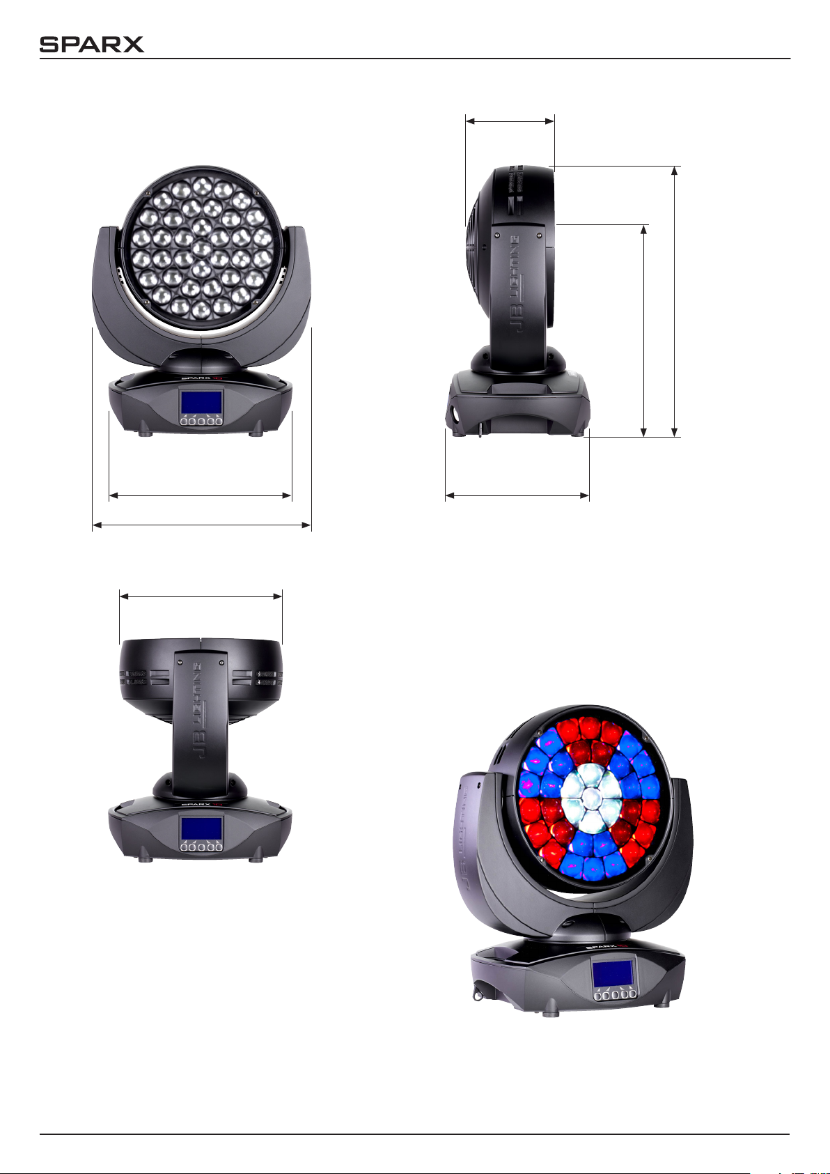
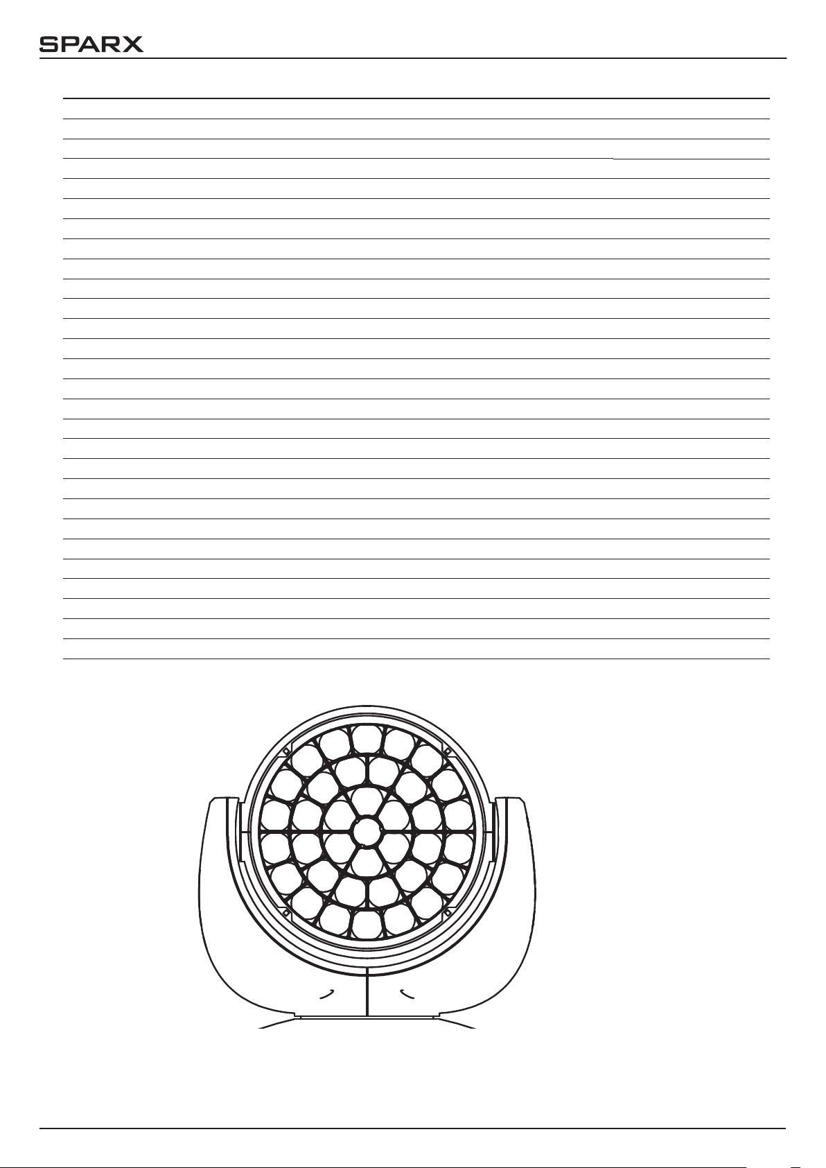
1. Maße und Produktübersicht
158,9
480
370
340
403,8
303
264,8
- 04 -
Page 5
10
2. Einleitung
2.1 Sicherheitshinweise
ACHTUNG:
!
!
Dieses Gerät ist nur für den professionellen Gebrauch geeignet!
Schutzart IP 20 - nur für den Gebrauch in trockener Umgebung (Indoor)!
LED Strahlung - Nicht im Abstand von weniger als 5m und nicht mit optischen Instrumenten in den Strahl blicken. LED-Klasse 3 entsprechend DIN EN 62471
ACHTUNG:
JB-Lighting Lichtanlagentechnik GmbH autorisiert den Gebrauch ihrer Geräte nicht
in lebensunterstützenden Systemen. Lebensunterstützende Systeme sind Systeme
deren Zweck dazu dient Leben zu erhalten oder zu stabilisieren und deren Defekt
oder Fehlfunktion möglicherweise den Tod oder die Verletzung von Personen nach
sich ziehen.
Das Produkt dieser Bedienungsanleitung entspricht folgender EU-Richtlinien:
- Niederspannungsrichtlinie 2014/35/EU
- Elektromagnetische Verträglichkeit 2014/30/EU
2.2 Auspacken des Gerätes
Inhalt der Versandverpackung: Dieser Scheinwerfer, zwei Omega-Bügel mit Bajonett-Verschlüssen, Powercon-Kabel und einmal diese Anleitung pro Sendung.
Öffnen Sie die Verpackung an der Oberseite und entnehmen Sie das Inlay und die beiden
Omega-Bügel. Überprüfen Sie den Sparx10 auf eventuelle Transportschäden, diese sollten umgehend dem Transportunternehmen mitgeteilt werden.
3. Installation
3.1 Netzanschluss
ACHTUNG:
!
Dem Scheinwerfer Sparx10 liegt ein teil-konfektioniertes Stromkabel mit PowerCon-Anschluss
bei (in US-Ausführung ist das Anschlusskabel nicht enthalten). Die Montage des Schutzkontaktstecker, bzw. der Anschluss des Sparx10 an die Stromversorgung (100-240 Volt, 50 - 60 Hertz),
muss von einem autorisierten Fachmann durchgeführt werden.
Anschluss EU-Model:
Leiterfarbe Funktion Symbol
Braun Phase „L“
Netzanschluss nur von einem Fachmann durchführen lassen!
Blau Neutralleiter „N“
Grün/Gelb Schutzleiter
- 05 -
Page 6
10
Anschluss außerhalb der EU:
Weltweit gibt es unterschiedliche Netzausführungen. Der Sparx10 darf nur an folgenden Stromnetzen betrieben werden:
2 Leiter,
1 Phase
Netz
L
N
Sparx10
L
N
PE
3 Leiter,
1 Phase
4 Leiter,
3 Phasen
L
N
L
L
L
L
N
L
PE
N
1
2
3
L
N
PE
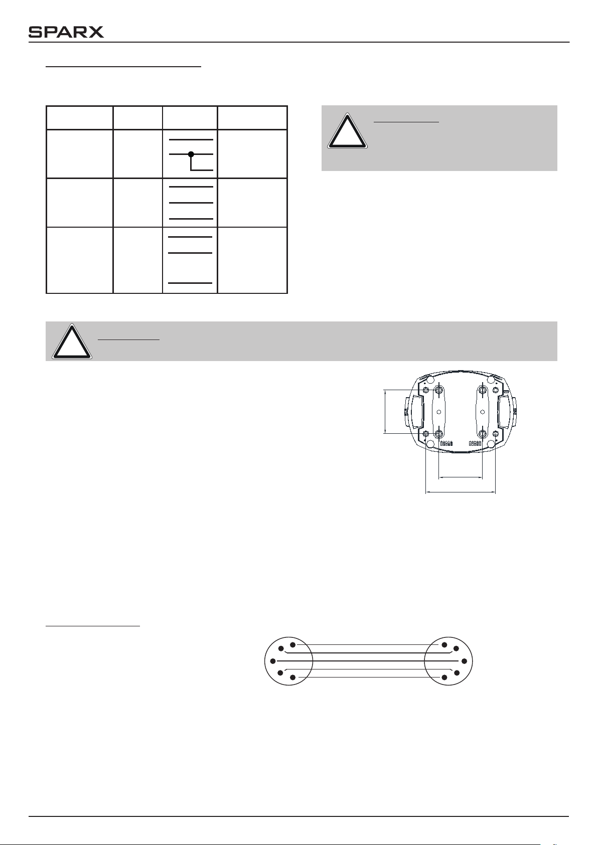
3.2 Montage der Geräte
ACHTUNG: Mindestens 1,0 m Abstand zu brennbaren Gegenständen!
!
Sparx10 immer mit Sicherungsseil zusätzlich sichern!
Der Sparx10 darf stehend nur auf einer harten Unterlage betrieben werden, die im Bodenblech ein gestanzten
Lüftungsschlitze müssen frei bleiben. Bei Verwendung
der Standard-Omega-Bügel kann der Sparx10 in beliebiger Position montiert werden. Verwenden Sie bei der
Montage immer beide Standard-Omega-Bügel. Achten
Sie darauf, das die Camlocs richtig eingerastet sind. Der
Sparx10 muss immer zusätzlich mit Sicherungsseil an der
Sicherungsöse gesichert werden.
ACHTUNG:
!
Der Sparx10 darf in Kanada nur
im 2 Leiter, 1 Phasen Netz maximal mit 120V betrieben werden!
140
140
224
3.3 DMX-Verkabelung
Die DMX Verkabelung (Signalleitungen) sollte mit einem 4-poligen Kabel mit Abschirmung erfolgen. Wir empfehlen ein DMX-Kabel, alternativ kann auch ein 2-poliges Mikro-Kabel verwendet
werden. Damit ist jedoch kein Software-Update möglich, da Pin 4 und 5 nicht belegt sind. Bei
den Steckern und Buchsen handelt es sich um 5-polige oder 3-polige XLR Verbinder, die im
Fachhandel erworben werden können.
Steckerbelegung:
Pin1 = Ground / Abschirmung
1
2
Kabel mit Abschirmung
1
2
Pin2 = DMX Pin3 = DMX +
Pin4 = Data out Pin5 = Data out +
3
4
5
5
3
4
- 06 -
Page 7
10
Der Sparx10 verfügt über je zwei DMX-in und DMX-out Anschlüsse, die jeweils parallel durch
verbunden sind. Benutzen Sie pro Scheinwerfer jeweils nur einen DMX-in und DMX-out Anschluss! Die Geräte können nicht als DMX-Splitter benutzt werden.
Verbinden Sie nun den DMX-Ausgang Ihres Controllers mit dem 1. Sparx10 (Controller DMX-Out
-> Sparx10 DMX-In). Anschließend den 1. Sparx10 mit dem 2. Sparx10 (Sparx10 DMX-Out ->
Sparx10 DMX-In) und so weiter. Alle DMX-Ein/Ausgänge sind durch kontaktiert, d.h. Sie können
den 3-poligen DMX-In in Kombination mit dem 5-poligen DMX-Out Anschluss benutzen. In manchen Fällen ist es ratsam einen so genannten Endstecker (XLR-Stecker mit einem Widerstand
von 120 Ohm zwischen Pin 2 und Pin 3) einzustecken. Ob ein Endstecker benötigt wird hängt
von verschiedenen Faktoren ab, unter anderem den benutzten Kabellängen und der Geräte Anzahl. Solange jedoch keine Probleme in der DMX-Linie auftreten, kann darauf verzichtet werden.
3.4 Netzstrom verkabeln
Anschlusswerte: Spannung 100-240 V, Frequenz 50 - 60 Hz, Leistung max. 600 VA
Die elektrische Sicherheit sowie die Funktion des Gerätes ist nur dann gewährleistet, wenn es
an ein vorschriftsmäßig installiertes Schutzleitersystem angeschlossen wird. Es ist sehr wichtig,
dass diese grundlegende Sicherheitsvoraussetzung vorhanden ist. Lassen Sie im Zweifelsfall
die Elektroinstallation durch einen Fachmann überprüfen. Der Hersteller kann nicht für Schäden
verantwortlich gemacht werden, die durch einen fehlenden oder unterbrochenen Schutzleiter
oder durch unsachgemäßen Anschluss verursacht wurden! (z. B. Elektrischer Schlag). Benutzen
Sie das Gerät nur im komplett zusammengebauten Zustand, damit keine elektrischen Bauteile
berührt werden können. (Gefahr 100-240 V)
Wenn Sie die aufgeführten Punkte beachtet haben, können Sie die Geräte einstecken, oder von
einem Fachmann an das Netz anschließen lassen.
ACHTUNG: Der Sparx10 kann sofort aueuchten falls Standalone-Betrieb
!
3.5 Netzdurchgang verkabeln
!
Der Sparx10 verfügt über einen PowerCon-Netzausgang. Entsprechend der örtlichen Gegebenheiten können mehrere Geräte durch PowerCon-IN und PowerCon-OUT verlinkt werden. Verbinden Sie maximal fünf Sparx10 in einer Kette. Nutzen Sie dafür ein zugelassenes dreiadriges
Kabel mit min. 1,5 mm² Querschnitt. Die Verkabelung muss mit den kodierten Originalsteckern
von Neutrik erfolgen. Dabei sind die Installationshinweise vom Hersteller (www.neutrik.com) und
die Farbkodierung des Kabels zu beachten.
Leiterfarbe Funktion Symbol
Braun Phase „L“
Blau Neutralleiter „N“
aktiviert ist oder ein DMX-Signal anliegt!
ACHTUNG: Nur von einem Fachmann durchführen lassen!
Grün/Gelb Schutzleiter
- 07 -
Page 8
10
4. Bedienfeld
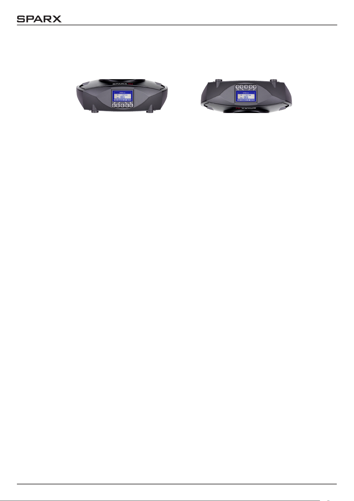
Der Sparx10 verfügt über ein grasches Display, dass bei hängender Installation um 180° gedreht werden kann.
Drehen des Displays
Die aktuelle Ausrichtung des Displays wird durch Drücken der mittleren Taste bestimmt.
Am Bedienfeld können sämtliche Parameter des Sparx10 eingestellt werden (siehe Menü-Übersicht nächste Seite).
Im Hauptmenü lässt sich die Adresse direkt einstellen. Durch Drücken der rechten Base-Taste
beim Einstecken des Sparx10 wird überdies der Resetvorgang abgebrochen damit eine Adressierung auch im Case erfolgen kann. Ebenso informiert das Hauptmenü über den eingestellten DMXMode und bei eingeschaltetem Wireless Mode über die Feldstärke des zugehörigen Sendemoduls.
Durch “ENTER” wird ein Untermenü aufgerufen oder eine Eingabe bestätigt, “ESC” dient zum
Verlassen einer Funktion oder eines Menüpunktes, „UP“ und „DOWN“ dient zum Navigieren innerhalb des Menüs und zur Eingabe von Werten.
Besondere Bereiche können nur über eine Tastenkombination aufgerufen werden. Dabei wird
die Taste “ENTER” gedrückt (gedrückt halten) und dann zusätzlich mit der gegenüberliegenden
Taste “ESC” der Zugang zum Menü freigeschaltet. Dies gilt im SERVICE-Bereich für die Funktion
FINE ADJUST, sowie im STANDALONE Bereich für die Funktionen MODIFY, RUN und REMOTE.
Das Verlassen der Funktion erfolgt dann mit „ESC“ (gedrückt halten) und gleichzeitigem Drücken
von „ENTER“, der Bereich MODIFY und FINE ADJUST kann mit „ESC“ verlassen werden.
Außerdem lässt sich das Hauptmenü gegen unbeabsichtigten Zugriff sperren. Die Sperrung erfolgt ebenfalls durch Drücken der Taste “ENTER” (gedrückt halten) und dann zusätzlich mit der
gegenüberliegenden Taste “ESC” sperren. Das Verlassen der Funktion erfolgt hierbei in umgekehrter Reihenfolge.
Der Displaybeleuchtung werde besondere Funktionen zugeordnet.
Während des Resets bleibt die Displaybeleuchtung ausgeschaltet. Langsam blinkende Displaybeleuchtung bei der Anzeige JB-Lighting bedeutet es liegt kein DMX-Signal an.
Schnell blinkende Displaybeleuchtung bei der Anzeige JB-Lighting bedeutet, das in der
„ERROR LIST“ ein Fehler abgespeichert ist, der noch nicht gelöscht wurde (löschen folgende
Seite, Menü-Übersicht - Service). Schnell blinkende Displaybeleuchtung bei einer Fehlermeldung im Display (z.B. *PAN TIMEOUT) zeigt einen aktuellen Fehler an. Wenden Sie sich in diesem Fall an Ihren Händler oder unsere Serviceabteilung. Empfängt der Sparx10 ein DMX-Signal
erlischt die Displaybeleuchtung nach 30 Sekunden.
- 08 -
Page 9
10
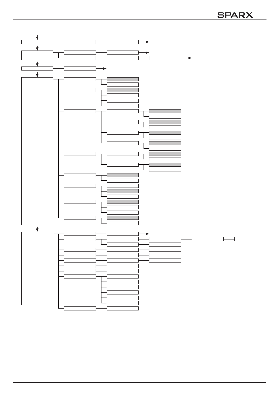
4.1 Menü-Übersicht
ENTER
FACTORY DEF. LOAD DEFAULTS SURE?
UP
USER DEFAULTS
DMX ADDRESS ADDRESS +/-
ENTER ENTER
LOAD DEFAULTS SURE?
SAVE DEFAULTS SURE? PASSWORD
PERSONALITY
DMX INPUT MODE WIRED
WIRED/WIRELESS
DMX MODE MODE 1
MODE 2
MODE 3
MODE 4
PAN / TILT RESOLUTION
PAN INVERS
TILT INVERS
PAN/TILT SWAP
CURVES DIMMER CURVE SQUARE
RGB CURVE SQUARE
SHORTEST DIST. ON
OFF
CAMERA MODE 50 Hz
60 Hz
FLEX
COOLING MODE STANDARD
SILENT
HIGH-POWER
WLJB DMX HOLD FADE OUT
DMX HOLD
16 BIT
8 BIT
NORMAL
INVERS
NORMAL
INVERS
NORMAL
INVERS
LINEAR
LINEAR
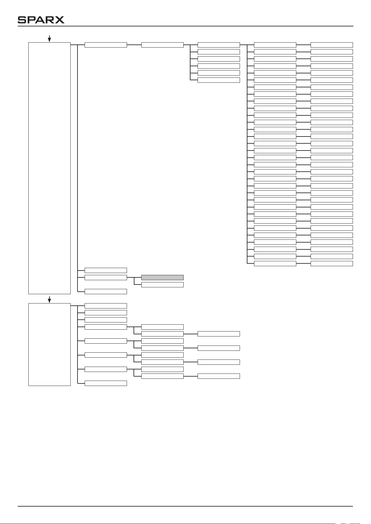
SERVICE
RESET FIXTURE SURE?
ERROR LIST LIST
CLEAR
FUNCTION TEST START TEST
LED TEST START TEST TEST RUNNING
DMX TEST DMX CHANNEL CH 001: --- +/-
INIT PAN/TILT
DISPLAY CONTR. D. CONTR: +000 +/-
FINE ADJUST
RECEIVE SOFTW. SURE?
SURE?
SKAL RED
SKAL GREEN
SKAL BLUE
SKAL WHITE
SKAL ALL
OFS ZOOM
PAN TIMEOUT COUNT: 1 CLEAR?
SURE?
TEST RUNNING
- 09 -
Page 10
10
STANDALONE
EDIT STEP NR. +/-
RUN
TIMEBASE 1 SEC
1/10 SEC
REMOTE
MODIFY
CAPT DMX
INSERT
DELETE
RESET STEP
CLEAR ALL
FADE TIME FADE TIME +/-
NEXT TIME NEXT TIME +/-
PAN PAN +/-
TILT TILT +/-
CONTROL CONTROL +/-
SHUTTER SHUTTER +/-
DIMMER DIMMER +/-
ZOOM ZOOM +/-
MAPPING MAPPING +/-
PATTERN MODE PATT. MODE +/-
PATTERN PATTERN +/-
PATTERN SPEED PATTERN SP. +/-
COLOR SPREAD COL. SPREAD +/-
SPARKLE SPARKLE +/-
SPARKLE SPEED SPARKLE SP. +/-
CTC 3200K
COLOR
SPEED PAN/TILT
SPEED EFFEKT
MOVE BLACKOUT
RED GLOW
GREEN GLOW
BLUE GLOW
WHITE GLOW
RED
GREEN
BLUE
WHITE
RED PATTERN
GREEN PATTERN
BLUE PATTERN
WHITE PATTERN
CTC 3200K +/-
COLOR +/-
SPEED P/T +/-
SPEED EFFEKT +/-
MOVE BO. +/-
RED GLOW +/-
GREEN GLOW +/-
BLUE GLOW +/-
WHITE GLOW +/-
RED +/-
GREEN +/-
BLUE +/-
WHITE +/-
RED PATTERN +/-
GREEN PATT. +/-
BLUE PATTERN +/-
WHITE PATT. +/-
INFO
SOFTWARE VER.
FIRMWARE VER.
TOT OPERAT. TIME
TEMP BASE LCD ACTUAL
MAX RESET?
TEMP BASE PS ACTUAL
MAX RESET?
TEMP HEAD DRV ACTUAL
MAX RESET?
TEMP HEAD LED ACTUAL
MAX RESET?
TEMP HEAD LEDS
- 10 -
Page 11

10
4.2 FACTORY DEFAULTS - Werkseinstellungen
Um den Sparx10 auf die Werkseinstellung zurück zu setzen, gehen Sie auf den Menüpunkt
FACTORY DEFAULTS -> LOAD DEFAULTS. Nach dem Bestätigen der Sicherheitsabfrage SURE?
mit “ENTER” werden alle Parameter auf Werkseinstellung zurück gesetzt. Der aktuelle Weißabgleich (Kapitel 6.1) bleibt bei der Rücksetzung erhalten.
4.3 USER DEFAULTS - Benutzereinstellungen
Hat der Benutzer den Sparx10 im PERSONALITY Menü auf seine persönlichen Einstellungen
programmiert, so können diese im USER DEFAULTS Menü abgespeichert und geladen werden.
Um unbeabsichtigtes verändern der Daten zu verhindern muss beim Speichervorgang als Passwort: „JB-LIGHTING“ eingegeben werden.
4.4 DMX ADDRESS - DMX Adressierung
Die DMX Adressierung kann direkt im Display vorgenommen werden. Durch Drücken der Taste
„UP“ oder „DOWN“ stellen Sie die gewünschte DMX-Adresse ein. Mit der Taste „ENTER“ wird
der Wert bestätigt. Die DMX Adressierung kann aber auch innerhalb des Menüs unter DMX
ADDRESS vorgenommen werden.
4.5 PERSONALITY - Persönliche Einstellungen DMX INPUT MODE
Im Sparx10 ist werksseitig ein Funk-DMX-Empfangsmodul eingebaut. Um dieses in Verbindung
mit dem JB-Lighting Wireless TRX Sendemodul zu benutzen lässt sich der Menüpunkt WIRED
(Werkseinstellung) auf WIRED/WIRELESS umstellen. Der Login des Empfängers auf den Sender
erfolgt über die „Start“ Taste (siehe hierzu Bedienungsanleitung Wireless TRX). Hat sich das
Gerät eingeloggt wird der entsprechende Funkkanal angezeigt. Eine Pegelanzeige im Display
informiert über die aktuelle Empfangsqualität. Wird der Sparx10 zusätzlich über die DMX Anschlussbuchsen angeschlossen, so hat dieses Signal Priorität vor der Funkstrecke.
DMX MODE
Der Sparx10 verfügt über 3 Betriebsmodi (siehe Kanalbelegung). Über den Mode 1 lassen sich
alle Parameter des Sparx10 bedienen. Durch die Wahlmöglichkeit Mode 2 - 16 Bit auf RGBW
lassen sich die Farbkanäle feiner justieren. Um DMX-Kanäle einzusparen lässt sich der Sparx10
im Mode 3 auf 24 Kanäle reduzieren.
PAN / TILT
Unter RESOLUTION lässt sich die Bewegungsauösung von 16 Bit auf 8 Bit einstellen. In
der Werkseinstellung ist diese auf 16 Bit eingestellt. In der 8 Bit Auösung lässt sich der P8
weniger exakt positionieren, je nach Lichtkonsole jedoch schneller bedienen. Die Menüpunkte
PAN INVERS und TILT INVERS ermöglichen ein Invertieren der Bewegungsrichtung. Unter PAN/
TILT SWAP lassen sich die Kanäle Pan und Tilt vertauschen.
CURVES
Die Dimmerkurve, sowie die RGBW Farbmischkurven lassen sich jeweils von exponential (square)
auf linear (linear) umstellen. In der Exponentialkurve (Werkseinstellung) bewirkt dies ein weicheres Ein- und Ausblendverhalten des Dimmers, sowie ein sanfteres Überblenden der RGBWFarbmischung.
- 11 -
Page 12

10
SHORTEST DISTANCE
Dieser Menüpunkt spricht nur auf den Farbradkanal an. Der Farbradkanal simuliert das Farbrad
unserer konventionellen Moving-Heads. In der Werkseinstellung (ON) wechseln die Farben über
die kürzeste Distanz zueinander. Ein Umstellen auf OFF bewirkt, dass der Farbwechsel nur über
die konventionelle Reihenfolge erfolgt.
CAMERA MODE
Um ein Flimmern bei TV Aufnahmen zu vermeiden, lässt sich der Sparx10 an verschiedene Kamerasysteme von 50 Hertz (PAL, Secam) auf 60 Hertz (NTSC) anpassen. Der Flex Mode wird
eingestellt falls abweichende Kamerasysteme benutzt werden. Ab Werk ist der Sparx10 auf 60
Hertz eingestellt. Die Umstellung ist auch mit dem Lichtmischpult über den Steuerkanal möglich.
COOLING MODE
Im Menüpunkt COOLING MODE lässt sich die Lüftersteuerung des Sparx10 einstellen. Die
STANDARD-Einstellung sollte in den meisten Fällen gewählt werden. Mit der Umschaltung auf
SILENT lassen sich die Lüftergeräusche auf ein Minimum reduzieren. Der Zeitraum für diese
Einstellung sollte begrenzt sein und nur in ausreichend belüfteten Räumen benutzt werden. Bei
Festinstallationen, sowie schlecht belüfteten Räumen sollte der HI POWER Mode eingestellt werden. Eine Gefahr für die Lebensdauer des Geräts besteht in keinem Modus, da der Sparx10 über eine
Temperatur-Sicherheitsabschaltung verfügt.
WLJB DMX HOLD
Hier lässt sich die Vorentscheidung treffen was bei Signalverlust im Wireless DMX Betrieb geschehen soll. Bei Wireless Hold bleibt der Sparx10, wie im Wired Betrieb, bei seinem zuletzt
empfangenen Schritt stehen. Bei Fade out dimmt das Gerät nach 5 Sekunden aus. Bei Signalempfang fährt der Sparx10 zuerst auf seine neue Position und dimmt dann wieder ein.
4.6 STANDALONE Betrieb
Im Standalone-Betrieb können bis zu 20 Programmschritte im Sparx10 gespeichert werden, die
dann als Endlosschleife ablaufen. Die Speicherung der Bilder kann dabei auf zwei Arten erfolgen.
Entweder Sie stellen die gewünschten DMX-Werte direkt am Sparx10 ein und speichern diese
ab, oder Sie stellen die DMX-Werte über ein angeschlossenes DMX-Pult ein und speichern diese
anschließend im Sparx10 ab.
Die Menüpunkte MODIFY, RUN und REMOTE können nur mit Hilfe einer Tastenkombination aufgerufen werden. Dazu Drücken Sie “ENTER”, halten diese Taste gedrückt und drücken zusätzlich
„ESC“. Entfernen Sie vor dem Aktivieren dieser Menü-Punkte alle anderen Geräte in der DMXLinie, die DMX senden, wie z.B. Pulte oder andere Scheinwerfer, die nicht als Slave-Geräte konguriert sind, da sonst gegebenenfalls Beschädigungen an den DMX-Treibern auftreten können.
Programmieren des Standalone Programms am Scheinwerfer-Display:
Rufen Sie den Menüpunkt STANDALONE, EDIT auf. Im Menüpunkt STEP NR+/- wählen Sie den
gewünschten Step aus und können diesen und seine Kanalparameter in den folgenden Menüpunkten verändern:
Im Menüpunkt MODIFY stellen Sie die gewünschte Lichtstimmung und Position ein und bestimmen mit FADE TIME (Einblendzeit) und NEXT TIME (Zeit des gesamten Schritts) die einzelnen
Ablaufzeiten der Schritte.
Mit INSERT fügen Sie einen zusätzlichen Programmschritt ein. Die DMX-Werte des vorigen
Schritts werden in den neuen Schritt kopiert.
Mit DELETE löschen Sie einen Schritt heraus. Das Display zeigt Ihnen dabei STEP NR: 1/X an.
Mit den Auswahltasten gehen Sie dabei auf den gewünschten Schritt.
- 12 -
Page 13

10
Mit RESET STEP setzen Sie einen Schritt auf seinen Ursprungswert (DMX 000) zurück. Das Display zeigt Ihnen dabei STEP NR: 1/X an. Mit den Auswahltasten suchen Sie sich Ihren Schritt
aus. Mit CLEAR ALL setzen Sie die kompletten Standalone-Programmschritte zurück. Unter
MODIFY nden Sie danach wieder STEP1/1. Im Menüpunkt STANDALONE, TIMEBASE haben
Sie die Möglichkeit die Fade Time und Next Time von 1 Sekunde auf 1/10 Sekunde umzustellen.
Übernehmen der DMX Werte von einem externen Pult:
Um die DMX-Werte eines angeschlossenen Pultes zu übernehmen müssen Sie zuerst den
Capture DMX Eingang freischalten. Hierzu gehen Sie zum Menüpunkt CAPT DMX. Das Display zeigt Ihnen jetzt CAPTURE DMX 01/01, mit der Übernahmetaste schalten Sie auf START
CAPTURE. Nun reagiert der Sparx10 auf die Signale des externen Pultes.
Start des Standalone-Programms:
Rufen Sie das STANDALONE-Menü auf und navigieren Sie bis zum Untermenü RUN. Bestätigen die Auswahl durch Drücken der Tastenkombination “ENTER” drücken, gedrückt halten und
gleichzeitig “ESC”. Das Display zeigt dann: S-ALONE: 01/XX und das Programm läuft in einer
Endlosschleife ab.
Deaktivieren: Drücken Sie die Taste “ESC”, halten Sie diese gedrückt und drücken Sie dann
zusätzlich “ENTER”. Das Menü springt eine Ebene zurück und RUN wird im Display dargestellt.
Betrieb über Master-Slave Funktion:
Verbinden Sie die Sparx10 über DMX Leitungen, aktivieren Sie bei allen Slave-Geräten den
Menüpunkt REMOTE. Navigieren Sie dazu im STANDALONE-Menü bis zum Untermenü
REMOTE. Aktivieren Sie die Funktion REMOTE durch die Tastenkombination “ENTER” drücken,
gedrückt halten und zusätzlich “ESC” drücken. Der Scheinwerfer bendet sich im Slave-Modus,
wenn im Display der Status REMOTE INACTIVE oder REMOTE ACTIVE dargestellt wird.
REMOTE INACTIVE: Der Sparx10 bendet sich im Slave-Modus empfängt aber kein DMX-Signal.
REMOTE ACTIVE: Der Sparx10 bendet sich im Slave-Modus und empfängt ein DMX-Signal. Das
Master-Gerät wird über den Menüpunkt MODIFY programmiert und über RUN (durch die Tastenkombination “ENTER” drücken, gedrückt halten und zusätzlich “ESC” drücken) gestartet.
Preload Demo:
Über diesen Bereich können 20 werksseitig vorprogrammierte Effekte geladen werden. Diese
lassen sich über MODIFY verändern und somit wird das Kennenlernen der Sparx10 Effekte vereinfacht.
4.7 INFO
Hier werden Sie über den jeweiligen Software- und Firmwarestand informiert. Im Menüpunkt
TOT OPERATE TIME werden die Gesamtstunden des Sparx10 gespeichert. Diese können nicht
zurückgesetzt werden.
Der Sparx10 überprüft laufend über Temperatursensoren seine Betriebstemperatur. Diese können in folgenden Bereichen ausgelesen werden:
TEMP BASE LCD - Leiterkarte Bedienfeld
TEMP BASE PS - Netzteil
TEMP HEAD DRV - LED Treiberplatine
TEMP HEAD LED - Durchschnittstemperaturen LEDs
Diese Werte zeigen jeweils die aktuelle sowie die maximale Temperatur. Diese Maximalwerte
können einzeln gelöscht werden.
Als letzter Menüpunkt werden noch die TEMP HEAD LEDS - Einzeltemperaturen der LED´s angezeigt
- 13 -
Page 14

10
5. Kanalbelegung
Der Sparx10 verfügt über 4 unterschiedliche DMX-Modi. Der jeweilige Modus lässt sich im
Menüpunkt PERSONALITY -> DMX MODE einstellen. Der eingestellte Modus wird im Hauptmenü
angezeigt.
Mode 1(M1) Mode 2 (M2) Mode 3 (M3) Mode 4 (M4)
Kanal 1 Pan Pan Pan Pan
Kanal 2 Pan fein Pan fein Pan fein Pan fein
Kanal 3 Tilt Tilt Tilt Tilt
Kanal 4 Tilt fein Tilt fein Tilt fein Tilt fein
Kanal 5 Steuerkanal Steuerkanal Steuerkanal Steuerkanal
Kanal 6 Shutter Shutter Shutter Shutter
Kanal 7 Dimmer Dimmer Dimmer Dimmer
Kanal 8 Zoom Zoom Zoom Zoom
Kanal 9 Segmentauswahl Segmentauswahl Segmentauswahl Segmentauswahl
Kanal 10 Mustermodus Mustermodus Mustermodus Mustermodus
Kanal 11 Muster Muster Muster Muster
Kanal 12 Mustergeschwindigkeit Mustergeschwindigkeit Mustergeschwindigkeit Mustergeschwindigkeit
Kanal 13 Farbverlauf Farbverlauf Farbverlauf Farbverlauf
Kanal 14 Sparkle Sparkle Sparkle Sparkle
Kanal 15 Sparklegeschwindigkeit Sparklegeschwindigkeit Sparklegeschwindigkeit Sparklegeschwindigkeit
Kanal 16 CTC 3200K CTC 3200K CTC 3200K CTC 3200K
Kanal 17 Farbrademulation Farbrademulation Farbrademulation Farbrademulation
Kanal 18 Pan/Tilt-Geschwindigkeit Pan/Tilt-Geschwindigkeit Pan/Tilt-Geschwindigkeit Pan/Tilt-Geschwindigkeit
Kanal 19 Effekt-Geschwindigkeit Effekt-Geschwindigkeit Effekt-Geschwindigkeit Effekt-Geschwindigkeit
Kanal 20 Blackout Move Blackout Move Blackout Move Blackout Move
Kanal 21 Rot Rot Rot Rot
Kanal 22 Grün Rot fein Grün Grün
Kanal 23 Blau Grün Blau Blau
Kanal 24 Weiß Grün fein Weiß Weiß
Kanal 25 Rot Blau Rot
Kanal 26 Grün Blau fein Grün
Kanal 27 Blau Weiß Blau
Kanal 28 Weiß Weiß fein Weiß
Kanal 29 Rot Rot Rot
Kanal 30 Grün Rot fein Grün
Kanal 31 Blau Grün Blau
Kanal 32 Weiß Grün fein Weiß
Kanal 33 Blau Überblendung (Crossfade)
Kanal 34 Blau fein Rot (LED-Gruppe 1)
Kanal 35 Weiß Grün (LED-Gruppe 1)
Kanal 36 Weiß fein Blau (LED-Gruppe 1)
Kanal 37 Rot Weiß (LED-Gruppe 1)
Kanal 38 Rot fein Rot (LED-Gruppe 2)
Kanal 39 Grün Grün (LED-Gruppe 2)
Kanal 40 Grün fein Blau (LED-Gruppe 2)
Kanal 41 Blau Weiß (LED-Gruppe 2)
Kanal 42 Blau fein Rot (LED-Gruppe 3)
Kanal 43 Weiß Grün (LED-Gruppe 3)
Kanal 44 Weiß fein Blau (LED-Gruppe 3)
Kanal 45 Weiß (LED-Gruppe 3)
Glow RGBW
}
Main RGBW
}
Pattern RGBW
}
}
}
}
Glow RGBWMain RGBW
Pattern RGBW
Glow RGBW
}
Main RGBW
}
Pattern RGBW
}
- 14 -
Page 15

10
Mode 1(M1) Mode 2 (M2) Mode 3 (M3) Mode 4 (M4)
Kanal 46 Rot (LED-Gruppe 4)
Kanal 47 Grün (LED-Gruppe 4)
Kanal 48 Blau (LED-Gruppe 4)
Kanal 49 Weiß (LED-Gruppe 4)
Kanal 50 Rot (LED-Gruppe 5)
Kanal 51 Grün (LED-Gruppe 5)
Kanal 52 Blau (LED-Gruppe 5)
Kanal 53 Weiß (LED-Gruppe 5)
Kanal 54 Rot (LED-Gruppe 6)
Kanal 55 Grün (LED-Gruppe 6)
Kanal 56 Blau (LED-Gruppe 6)
Kanal 57 Weiß (LED-Gruppe 6)
Kanal 58 Rot (LED-Gruppe 7)
Kanal 59 Grün (LED-Gruppe 7)
Kanal 60 Blau (LED-Gruppe 7)
Kanal 61 Weiß (LED-Gruppe 7)
Kanal 62 Rot (LED-Gruppe 8)
Kanal 63 Grün (LED-Gruppe 8)
Kanal 64 Blau (LED-Gruppe 8)
Kanal 65 Weiß (LED-Gruppe 8)
l l
l l
l l
l l
l l
l l
l l
l l
Kanal 134 Rot (LED-Gruppe 26)
Kanal 135 Grün (LED-Gruppe 26)
Kanal 136 Blau (LED-Gruppe 26)
Kanal 137 Weiß (LED-Gruppe 26)
Kanal 138 Rot (LED-Gruppe 27)
Kanal 139 Grün (LED-Gruppe 27)
Kanal 140 Blau (LED-Gruppe 27)
Kanal 141 Weiß (LED-Gruppe 27)
Kanal 142 Rot (LED-Gruppe 28)
Kanal 143 Grün (LED-Gruppe 28)
Kanal 144 Blau (LED-Gruppe 28)
Kanal 145 Weiß (LED-Gruppe 28)
Kanal 146 Rot (LED-Gruppe 29)
Kanal 147 Grün (LED-Gruppe 29)
Kanal 148 Blau (LED-Gruppe 29)
Kanal 149 Weiß (LED-Gruppe 29)
Kanal 150 Rot (LED-Gruppe 30)
Kanal 151 Grün (LED-Gruppe 30)
Kanal 152 Blau (LED-Gruppe 30)
Kanal 153 Weiß (LED-Gruppe 30)
- 15 -
Page 16
10
Mode 1(M1) Mode 2 (M2) Mode 3 (M3) Mode 4 (M4)
Kanal 154 Rot (LED-Gruppe 31)
Kanal 155 Grün (LED-Gruppe 31)
Kanal 156 Blau (LED-Gruppe 31)
Kanal 157 Weiß (LED-Gruppe 31)
Kanal 158 Rot (LED-Gruppe 32)
Kanal 159 Grün (LED-Gruppe 32)
Kanal 160 Blau (LED-Gruppe 32)
Kanal 161 Weiß (LED-Gruppe 32)
Kanal 162 Rot (LED-Gruppe 33)
Kanal 163 Grün (LED-Gruppe 33)
Kanal 164 Blau (LED-Gruppe 33)
Kanal 165 Weiß (LED-Gruppe 33)
Kanal 166 Rot (LED-Gruppe 34)
Kanal 167 Grün (LED-Gruppe 34)
Kanal 168 Blau (LED-Gruppe 34)
Kanal 169 Weiß (LED-Gruppe 34)
Kanal 170 Rot (LED-Gruppe 35)
Kanal 171 Grün (LED-Gruppe 35)
Kanal 172 Blau (LED-Gruppe 35)
Kanal 173 Weiß (LED-Gruppe 35)
Kanal 174 Rot (LED-Gruppe 36)
Kanal 175 Grün (LED-Gruppe 36)
Kanal 176 Blau (LED-Gruppe 36)
Kanal 177 Weiß (LED-Gruppe 36)
Kanal 178 Rot (LED-Gruppe 37)
Kanal 179 Grün (LED-Gruppe 37)
Kanal 180 Blau (LED-Gruppe 37)
Kanal 181 Weiß (LED-Gruppe 37)
- 16 -
25
24
26
23
27
11
10
22
12
9
28
13 14
4
3
8
21
29
5
1
2
20
19
30
6
7
37
15
18
31
16
17
36
32
35
33
34
Die Pan/Tilt-Werte sind
hierbei auf 127/60 eingestellt. Das Display zeigt in
die gleiche Richtung wie
die LED‘s.
Page 17
10
M1 M2 M3 M4 Funktion DMX
1 1 1 1 Pan (X) Bewegung 433,6° 000-255
2 2 2 2 Pan (X) fein 000-255
3 3 3 3 Tilt (Y) Bewegung 333,3° 000-255
4 4 4 4 Tilt (Y) fein 000-255
5 5 5 5 Steuerkanal
100% Ausgangsleistung der LED-Stränge
Fade out über Fader (langsam - schnell)
Grundabgleich RGB
Fade out über Fader (langsam - schnell)
Weißabgleich RGB (Weiß wie bei Farbrademulation Farbe 0)
Fade out über Fader (langsam - schnell)
Abgleich für Color Picker (lineare RGB-Kurve)
Fade out über Fader (langsam - schnell)
}
Lichtmischpult
Mode1
(Reaktionszeit schnell)
000-007
008-015
016-023
024-031
100% Ausgangsleistung der LED-Stränge
Fade out über Fader (langsam - schnell)
Grundabgleich RGB
Fade out über Fader (langsam - schnell)
Weißabgleich RGB (Weiß wie bei Farbrademulation Farbe 0)
Fade out über Fader (langsam - schnell)
Abgleich für Color Picker (lineare RGB-Kurve)
Fade out über Fader (langsam - schnell)
}
}
}
Lichtmischpult
Mode 2
Lichtmischpult
Mode 3
Lichtmischpult
Mode 4
032-039
040-047
048-055
056-063
064-071
072-079
080-087
088-095
096-103
104-111
112-119
120-127
100% Ausgangsleistung der LED-Stränge
Fade out über Fader (langsam - schnell)
Grundabgleich RGB
Fade out über Fader (langsam - schnell)
Weißabgleich RGB (Weiß wie bei Farbrademulation Farbe 0)
Fade out über Fader (langsam - schnell)
Abgleich für Color Picker (lineare RGB-Kurve)
Fade out über Fader (langsam - schnell)
}
Lichtmischpult
Mode 5
(Reaktionszeit
langsam)
128-135
136-143
144-151
152-159
- 17 -
Page 18
10
Sicherheit
Camera Mode, 50Hz (nach 2 Sekunden)
Camera Mode, 60Hz (nach 2 Sekunden)
Camera Mode, FLEX (nach 2 Sekunden)
Sicherheit
Reset (nach 2 Sekunden)
Sicherheit
6 6 6 6 Shutter
Shutter zu
Shutter auf
Shutter pulsierend öffnen >20Hz (0,6sec - 4,8sec)
Shutter auf
Fade-Effekt mit Dimmer (langsam - schnell)
Shutter auf
Shutter zu
Shutter pulsierend öffnen <20Hz (0,6sec - 4,8sec)
Shutter auf
Shutter pulsierend schließen (0,6sec - 4,8sec)
Shutter zu
Shutter fade, 0% (0,6sec - 4,8sec)
Shutter auf
Shutter fade, 100% (0,6sec - 4,8sec)
Shutter zu
Shutter Zufall 100% (0,6sec - 4,8sec)
Shutter auf
Shutter Zufall 0% (0,6sec - 4,8sec)
Shutter zu
Shutter Zufall fade 0% (0,6sec - 4,8sec)
Shutter auf
Shutter Zufall fade 100% (0,6sec - 4,8sec)
Shutter auf
160-207
208-215
216-223
224-231
232-239
240-247
248-255
000-015
016-095
096-110
111-111
112-125
126-126
127-126
128-142
143-143
144-158
159-159
160-174
175-175
176-190
191-191
192-206
207-207
208-222
223-223
224-238
239-239
240-254
255-255
7 7 7 7 Dimmer 0 - 100% 000-255
8 8 8 8 Zoom 0-100% (nah 4° - weit 40°) 000-255
9 9 9 9 Mapping -
Segmentauswahl
Keine Segmentierung, Muster kreisförmig
Segment 01
Segment 02
Segment 03
Segment 04
Segment 05
Segment 06
Hintergrundfarbe (blau) - RGBW Main
Vordergrundfarbe (rot) - RGBW Pattern
Nicht aktiv (weiß) - bzw. RGBW Glow
000-000
001-001
002-002
003-003
004-004
005-005
006-006
007-007
008-008
009-009
- 18 -
010-010
Page 19
10
Segment 07
007-007
Segment 08
Segment 09
Segment 10
Segment 11
Segment 12
Segment 13
Segment 14
Segment 15
Segment 16
008-008
009-009
010-010
011-011
012-012
013-013
014-014
015-015
016-016
Segment 17
Segment 18
Segment 19
Segment 20
Segment 21
Segment 22
Segment 23
Segment 24
Segment 25
017-017
018-018
019-019
020-020
021-021
022-022
023-023
024-024
025-025
Segment 26
026-026
- 19 -
Page 20
10
Segment 27
027-027
Segment 28
Segment 29
Segment 30
Segment 31
Segment 32
Segment 33
Segment 34
Segment 35
Segment 36
028-028
029-029
030-030
031-031
032-032
033-033
034-034
035-035
036-036
Segment 37
Segment 38
Segment 39
Segment 40
Segment 41
Segment 42
Segment 43
Segment 44
Segment 45
037-037
038-038
039-039
040-040
041-041
042-042
043-043
044-044
045-045
- 20 -
Segment 46
046-046
Page 21
10
Segment 47
046-046
Segment 48
Segment 49
Segment 50
Segment 51
Segment 52
Segment 53
Segment 54
Segment 55
Segment 56
047-047
048-048
049-049
050-050
051-051
052-052
053-053
054-054
055-055
Segment 57
Segment 58
Segment 59
Segment 60
Segment 61
Segment 62
Segment 63
Segment 64
Segment 65
056-056
057-057
058-058
059-059
060-060
061-061
062-062
063-063
064-064
Segment 66
065-065
- 21 -
Page 22
10
Segment 67
067-067
Segment 68
Segment 69
Segment 70
Segment 71
Segment 72
Segment 73
Segment 74
Segment 75
Segment 76
068-068
069-069
070-070
071-071
072-072
073-073
074-074
075-075
076-076
Segment 77
Segment 78
Segment 79
Segment 80
Segment 81
Segment 82
Segment 83
Segment 84
Segment 85
077-077
078-078
079-079
080-080
081-081
082-082
083-083
084-084
085-085
- 22 -
Segment 86
Nicht belegt
086-086
087-099
Page 23

10
Ziffern 0-4
100-104
Ziffern 5-9
Smiley klein
Smiley groß
Nicht belegt
Statisches Segment 1
Statisches Segment 2
Statisches Segment 3
Statisches Segment 4
Statisches Segment 5
105-109
110-110
111-111
112-219
220-220
221-221
222-222
223-223
224-224
Statisches Segment 6
Statisches Segment 7
Statisches Segment 8
Statisches Segment 9
Statisches Segment 10
Statisches Segment 11
Nicht belegt
10 10 10 10 Pattern Mode - Muster Einstellungen
Bereich 0-31: RGBW LEDs des inaktiven Segments sind deaktiviert!
Muster frei laufend gefadet
Muster frei laufend geschaltet
Muster weiter schalten über Crossfade Laufrichtung vorwärts
Muster weiter schalten über Crossfade Laufrichtung rückwärts
Pixel zufällig ash schnell
Pixel zufällig snap open / ramp close
Pixel zufällig ash langsam
Pixel zufällig ramp open / snap close
regelmäßiger
Zeitabstand
}
225-225
226-226
227-227
228-228
229-229
230-230
231-255
000-000
001-001
002-002
003-003
004-004
005-005
006-006
007-007
- 23 -
Page 24

10
Pixel zufällig ash schnell
Pixel zufällig snap open / ramp close
Pixel zufällig ash langsam
Pixel zufällig ramp open / snap close
Statische Effekte
Bereich 32-63: RGBW LEDs des inaktiven Segments leuchten in Vordergrundfarbe (Pattern RGBW)
Muster frei laufend gefadet
Muster frei laufend geschaltet
Muster weiter schalten über Crossfade Laufrichtung vorwärts
Muster weiter schalten über Crossfade Laufrichtung rückwärts
Pixel zufällig ash schnell
Pixel zufällig snap open / ramp close
Pixel zufällig ash langsam
Pixel zufällig ramp open / snap close
Pixel zufällig ash schnell
Pixel zufällig snap open / ramp close
Pixel zufällig ash langsam
Pixel zufällig ramp open / snap close
Statische Effekte
Bereich 64-95: RGBW LEDs des inaktiven Segments leuchten in Hintergrundfarbe (Main RGBW)
Muster frei laufend gefadet
Muster frei laufend geschaltet
Muster weiter schalten über Crossfade Laufrichtung vorwärts
Muster weiter schalten über Crossfade Laufrichtung rückwärts
Pixel zufällig ash schnell
Pixel zufällig snap open / ramp close
Pixel zufällig ash langsam
Pixel zufällig ramp open / snap close
Pixel zufällig ash schnell
Pixel zufällig snap open / ramp close
Pixel zufällig ash langsam
Pixel zufällig ramp open / snap close
Statische Effekte
Bereich 96-127: RGBW LEDs des inaktiven Segments leuchten in Glow
RGBW. Glow RGBW überlagert auch die aktiven LEDs.
Muster frei laufend gefadet
Muster frei laufend geschaltet
Muster weiter schalten über Crossfade Laufrichtung vorwärts
Muster weiter schalten über Crossfade Laufrichtung rückwärts
Pixel zufällig ash schnell
Pixel zufällig snap open / ramp close
Pixel zufällig ash langsam
Pixel zufällig ramp open / snap close
Pixel zufällig ash schnell
Pixel zufällig snap open / ramp close
Pixel zufällig ash langsam
Pixel zufällig ramp open / snap close
Statische Effekte
Bereich 128-159: RGBW LEDs des inaktiven Segments leuchten in Glow
RGBW. Glow RGBW wird dabei nur für die inaktiven LED‘s verwendet!
Muster frei laufend gefadet
Muster frei laufend geschaltet
Muster weiter schalten über Crossfade Laufrichtung vorwärts
Muster weiter schalten über Crossfade Laufrichtung rückwärts
zufälliger
Zeitabstand
}
regelmäßiger
Zeitabstand
}
zufälliger
Zeitabstand
}
regelmäßiger
Zeitabstand
}
zufälliger
Zeitabstand
}
regelmäßiger
Zeitabstand
}
zufälliger
Zeitabstand
}
008-008
009-009
010-010
011-011
012-031
032-032
033-033
034-034
035-035
036-036
037-037
038-038
039-039
040-040
041-041
042-042
043-043
044-063
064-064
065-065
066-066
067-067
068-068
069-069
070-070
071-071
072-072
073-073
074-074
075-075
076-095
096-096
097-097
098-098
099-099
100-100
101-101
102-102
103-103
104-104
105-105
106-106
107-107
108-127
128-128
129-129
130-130
131-131
- 24 -
Page 25

10
Pixel zufällig ash schnell
Pixel zufällig snap open / ramp close
Pixel zufällig ash langsam
Pixel zufällig ramp open / snap close
Pixel zufällig ash schnell
Pixel zufällig snap open / ramp close
Pixel zufällig ash langsam
Pixel zufällig ramp open / snap close
Statische Effekte
Bereich 160-191: wie Bereich 0-31 jedoch ohne Glow RGBW
(wird verwendet mit Color Spread und geht dabei auf Vordergrundfarbe!)
Muster frei laufend gefadet
Muster frei laufend geschaltet
Muster weiter schalten über Crossfade Laufrichtung vorwärts
Muster weiter schalten über Crossfade Laufrichtung rückwärts
Pixel zufällig ash schnell
Pixel zufällig snap open / ramp close
Pixel zufällig ash langsam
Pixel zufällig ramp open / snap close
Pixel zufällig ash schnell
Pixel zufällig snap open / ramp close
Pixel zufällig ash langsam
Pixel zufällig ramp open / snap close
Statische Effekte
Makrobereich, kombinierte Effekte aus Segment,
Pattern Mode und Pattern Channel
Nicht belegt
regelmäßiger
Zeitabstand
}
zufälliger
Zeitabstand
}
regelmäßiger
Zeitabstand
}
zufälliger
Zeitabstand
}
132-132
133-133
134-134
135-135
136-136
137-137
138-138
139-139
140-159
160-160
161-161
162-162
163-163
164-164
165-165
166-166
167-167
168-168
169-169
170-170
171-171
172-191
192-235
236-255
11 11 11 11 Pattern - Ablaufmuster der Effekte
Muster inaktiv
Muster 1
Muster 2
Muster 3
Muster 4
Muster 5
Muster 6
000-000
001-001
002-002
003-003
004-004
005-005
006-006
Muster 7
Nicht belegt
Zufällige Ablaufmuster 1 - 7
Nicht belegt
007-007
008-127
128-135
136-255
- 25 -
Page 26

10
12 12 12 12 Pattern Speed - Muster Ablaufgeschwindigkeit
Laufrichtung vorwärts (schnell -> langsam)
Stopp
Laufrichtung rückwärts (langsam -> schnell)
13 13 13 13 Color spread - Farbverlauf
Farbverlauf inaktiv
Farbverlauf zunehmend indexierbar vorwärts
Farbverlauf zunehmend Laufrichtung vorwärts (schnell -> langsam)
Stopp
Farbverlauf abnehmend Laufrichtung vorwärts (langsam -> schnell)
Farbverlauf abnehmend indexierbar vorwärts
Farbverlauf zunehmend Laufrichtung vorwärts (schnell -> langsam)
Stopp
Farbverlauf abnehmend Laufrichtung vorwärts (langsam -> schnell)
14 14 14 14 Sparkle - Glittereffekt
Sparkle Effekt inaktiv
Sparkle Effekt Intensität (Minimum - Maximum)
15 15 15 15 Sparkle Geschwindigkeit
Sparkle Effekt gefadet (langsam -> schnell)
Sparkle Effekt geschaltet (langsam -> schnell)
Wiederholung der Fade- und Schaltblöcke
000-126
127-128
129-255
000-000
001-063
064-094
095-096
097-127
128-191
192-222
223-224
225-255
000-000
001-255
000-031
032-063
064-255
16 16 16 16 CTC 0 - 100% 000-255
17 17 17 17 Farbrademulation
Inaktiv, Farbmischung nur über RGB
Weiß
Weiß / Rot
Rot
Rot / Gelb
Gelb
Gelb / Magenta
Magenta
Magenta / Grün
Grün
Grün / Orange
Orange
Orange / Blau
Blau
Blau / Türkis
Türkis
Türkis / Weiß
Weiß 2700 Kelvin
Weiß 2700 Kelvin, halogenes ausdimmen
Weiß 3200 Kelvin
Weiß 3200 Kelvin, halogenes ausdimmen
Weiß 4200 Kelvin
Weiß 5600 Kelvin
Weiß 6500 Kelvin
Weiß 8000 Kelvin
Farbwechseleffekt (schnell - langsam)
Farbwechseleffekt (stopp)
Farbwechseleffekt (langsam - schnell)
000-001
002-003
004-007
008-011
012-015
016-019
020-023
024-027
028-031
032-035
036-039
040-043
044-047
048-051
052-055
056-059
060-063
064-064
065-065
066-066
067-067
068-068
069-069
070-070
071-191
192-222
223-224
225-255
- 26 -
Page 27

10
18 18 18 18 Pan/Tilt Geschwindigkeit
Bewegung in Echtzeit
Bewegung zeitverzögert (schnell - langsam)
19 19 19 19 Effektgeschwindigkeit
Effekte in Echtzeit
Effekte zeitverzögert (schnell - langsam)
20 20 20 20 Blackout Move
Ohne Funktion
Wahl der Segmente für Shuttereffekte in Verbindung mit dem Shutterkanal
Ohne Funktion
Blackout bei Pan/Tilt
Blackout bei Farbwechsel
Ohne Funktion
Blackout bei Pan/Tilt und Farbwechsel
Die Fadezeit des Dimmers ist einstellbar von langsam 5sec - max.
21 21 21 Rot (8 Bit) 0-100% 000-255
22 Rot fein (16 Bit) 0-100% 000-255
22 23 22 Grün (8 Bit) 0-100% 000-255
000-003
004-255
000-003
004-255
000-000
001-070
071-095
096-127
128-159
160-223
224-255
24 Grün fein (16 Bit) 0-100% 000-255
23 25 23 Blau (8 Bit) 0-100% 000-255
26 Blau fein (16 Bit) 0-100% 000-255
24 27 24 Weiß (8 Bit) 0-100% 000-255
28 Weiß fein (16 Bit) 0-100% 000-255
25 29 21 25 Rot (8 Bit) 0-100% 000-255
30 Rot fein (16 Bit) 0-100% 000-255
26 31 22 26 Grün (8 Bit) 0-100% 000-255
32 Grün fein (16 Bit) 0-100% 000-255
27 33 23 27 Blau (8 Bit) 0-100% 000-255
34 Blau fein (16 Bit) 0-100% 000-255
}
Glow RGBW
Main RGBW
28 35 24 28 Weiß (8 Bit) 0-100% 000-255
36 Weiß fein (16 Bit) 0-100% 000-255
}
- 27 -
Page 28

10
29 37 29 Rot (8 Bit) 0-100% 000-255
38 Rot fein (16 Bit) 0-100% 000-255
30 39 30 Grün (8 Bit) 0-100% 000-255
40 Grün fein (16 Bit) 0-100% 000-255
31 41 31 Blau (8 Bit) 0-100% 000-255
42 Blau fein (16 Bit) 0-100% 000-255
32 43 32 Weiß (8 Bit) 0-100% 000-255
44 Weiß fein (16 Bit) 0-100% 000-255
33 Überblendung interne Effektengine -> Einzel-LED-Ansteuerung 0-100% 000-255
34 Rot (LED-Gruppe 1) 0-100% 000-255
35 Grün (LED-Gruppe 1) 0-100% 000-255
36 Blau (LED-Gruppe 1) 0-100% 000-255
37 Weiß (LED-Gruppe 1) 0-100% 000-255
38 Rot (LED-Gruppe 2) 0-100% 000-255
39 Grün (LED-Gruppe 2) 0-100% 000-255
}
Pattern RGBW
40 Blau (LED-Gruppe 2) 0-100% 000-255
41 Weiß (LED-Gruppe 2) 0-100% 000-255
42 Rot (LED-Gruppe 3) 0-100% 000-255
43 Grün (LED-Gruppe 3) 0-100% 000-255
44 Blau (LED-Gruppe 3) 0-100% 000-255
45 Weiß (LED-Gruppe 3) 0-100% 000-255
46 Rot (LED-Gruppe 4) 0-100% 000-255
47 Grün (LED-Gruppe 4) 0-100% 000-255
48 Blau (LED-Gruppe 4) 0-100% 000-255
49 Weiß (LED-Gruppe 4) 0-100% 000-255
- 28 -
Page 29

10
50 Rot (LED-Gruppe 5) 0-100% 000-255
51 Grün (LED-Gruppe 5) 0-100% 000-255
52 Blau (LED-Gruppe 5) 0-100% 000-255
53 Weiß (LED-Gruppe 5) 0-100% 000-255
l
l
l
l
l
l
l
l
l
l
l
l
l
l
l
l
162 Rot (LED-Gruppe 33) 0-100% 000-255
163 Grün (LED-Gruppe 33) 0-100% 000-255
164 Blau (LED-Gruppe 33) 0-100% 000-255
165 Weiß (LED-Gruppe 33) 0-100% 000-255
166 Rot (LED-Gruppe 34) 0-100% 000-255
167 Grün (LED-Gruppe 34) 0-100% 000-255
168 Blau (LED-Gruppe 34) 0-100% 000-255
169 Weiß (LED-Gruppe 34) 0-100% 000-255
170 Rot (LED-Gruppe 35) 0-100% 000-255
171 Grün (LED-Gruppe 35) 0-100% 000-255
172 Blau (LED-Gruppe 35) 0-100% 000-255
173 Weiß (LED-Gruppe 35) 0-100% 000-255
174 Rot (LED-Gruppe 36) 0-100% 000-255
175 Grün (LED-Gruppe 36) 0-100% 000-255
176 Blau (LED-Gruppe 36) 0-100% 000-255
177 Weiß (LED-Gruppe 36) 0-100% 000-255
178 Rot (LED-Gruppe 37) 0-100% 000-255
179 Grün (LED-Gruppe 37) 0-100% 000-255
180 Blau (LED-Gruppe 37) 0-100% 000-255
181 Weiß (LED-Gruppe 37) 0-100% 000-255
- 29 -
Page 30

10
Anordnung der LED-Gruppen 1-37
Die Pan/Tilt-Werte sind hierbei auf 127/60 eingestellt, Das Display zeigt in die gleiche Richtung
wie die LED‘s.
29
28
27
30
31
13 14
26
12
15
32
5
25
11
4
16
6
33
1
24
10
3
7
17
34
2
22
9
21
8
20
23
5.1 Farbmischung
Der Sparx10 verfügt über einen Farbrademulationskanal, Main RGBW, Pattern RGBW, Glow
RGBW, sowie einen CTC Kanal. Um die Funktionen zu überschauen sind diese mit unterschiedlichen Prioritäten belegt. Der Farbradkanal hat erste Priorität vor der Main RGBW. Nur wenn der
Farbradkanal auf DMX-Wert 000-001 gesetzt ist, kann mit den RGBW Farbmischungen gearbeitet werden. Die RGBW Glow Kanäle dienen dazu ein Grundleuchten des Leuchtfeldes zu erzeugen um diese dann mit der RGBW zu überlagern. Der CTC Kanal kann sowohl in Kombination
mit dem Farbradkanal als auch mit der RGBW Farbmischung benutzt werden. Werden die Effektkanäle 9-13 eingesetzt werden, so fungiert Main RGBW als Hintergrundfarbe und Pattern RGBW
als Vordergrundfarbe (Musterfarbe). Ist die Farbrademulation aktiv so agiert Main RGBW als
Hintergrundfarbe und die Farbrademulation als Vordergrundfarbe (Musterfarbe). Pattern RGBW
ist hierbei inaktiv.
19
37
18
35
36
5.2 Steuerkanal
Über den Steuerkanal (Kanal 5) können die RGBW-Stränge zusätzlich abgeglichen betrieben
werden, dabei werden die abgeglichenen Modi hauptsächlich im Vermietbereich genutzt um bei
Zumietung von Geräten ein homogenes Ergebnis zu erzielen.
Im Bereich DMX 0-7: Unabgeglichener Modus, maximale Helligkeit der RGBW-Stränge.
Im Bereich DMX 8-15: Grundabgleich der Scheinwerfer, damit alle Scheinwerfer verschiedens-
ter Produktionsserien immer das gleiche Weiß liefern (Werksabgleich). Gegebenenfalls geringfügig reduzierte Helligkeit.
Im Bereich DMX 16-23: Weißabgleich, deutlich reduzierte Helligkeit bei der Farbe Blau, gegebenenfalls geringfügig reduzierte Helligkeit der anderen Grundfarben. Durch diese Einstellung ist
der Weißton gleich dem Weißton der Farbrademulation wenn alle RGB-Kanäle auf 100% Intensität eingestellt sind.
Im Bereich DMX 24-31: Abgleich wie im Bereich 16-23 DMX, jedoch wird hier die RGBW-Farbmischkurve zusätzlich auf lineare Farbmischung gesetzt, um die Verwendung von Farb-, bzw.
Color-Picker Funktionen diverser Lichtsteueranlagen zu ermöglichen.
Diese Bereiche werden auf dem Steuerkanal 5x wiederholt um das Ansprechverhalten des
Sparx10 an Lichtsteuerungen verschiedenster Hersteller anzupassen. Hierbei läuft das Ansprechverhalten von schnell (Mode1) nach langsam (Mode 5).
- 30 -
Page 31

10
5.3 Benutzerhinweise Steuerkanal Kanal 5
Verschiedene Lichtsteuerkonsolen geben bei gefadeten oder über Fader bediente Lichtstimmungen nicht jeden DMX Wert aus, sie überspringen mehr oder weniger DMX Werte. Um ein
ashen oder shuttern des Sparx10 beim Ausdimmen oder Farbwechseln zu vermeiden stehen
daher 5 Modi zur Auswahl. Je nach Wahl des Modus wird aber auch die Reaktionszeit des
Scheinwerfers herabgesetzt.
Mapping Kanal 9
Dieser Kanal splittet die kreisförmig ablaufenden Muster des Patternkanals auf verschiedene
LED Segmente auf.
Pattern Mode Kanal 10
Übergreifend auf Mapping, Pattern und Pattern Speed kontrolliert der Pattern Mode ob ein Effekt
gefadet, geschaltet, statisch oder über Pixelashs abläuft. Ein Makrobereich hilft darüber hinaus
Effekte einfach zu programmieren.
Pattern / Pattern Geschwindigkeit Kanal 11/12
Der Musterkanal erzeugt zunehmende, abnehmende, zufällige Muster die über den Geschwindigkeitskanal geregelt werden. Ohne aktiven Mapping Kanal laufen diese immer Kreisförmig ab.
Der Pattern Mode Kanal bestimmt dabei auf welche Weise dies geschieht.
Color Spread Kanal 13
Dieser Kanal generiert einen indexierbaren oder durchlaufenden Farbverlauf über die Vordergrundfarbe des Effekts.
Sparkle / Sparkle Geschwindigkeit Kanal 14/15
Diesem Kanal verdankt der Sparx10 seinen Namen. Hiermit können einzigartige Glittereffekte in
Verbindung mit Dimmer und Zoom erzeugt werden. Je nach Intensität wird das Leuchtfeld auf
seine Grundfarben aufgesplittet. D.h. bei Vollfarben wird ein Ein-/Ausdimmen der Einzel LED´s
erzeugt. Bei einer Mischfarbe spaltet sich diese auf Ihre Grundfarben auf.
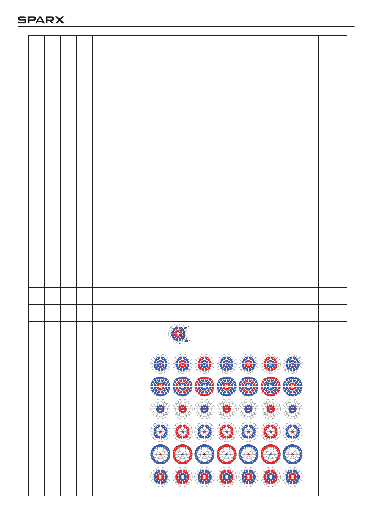
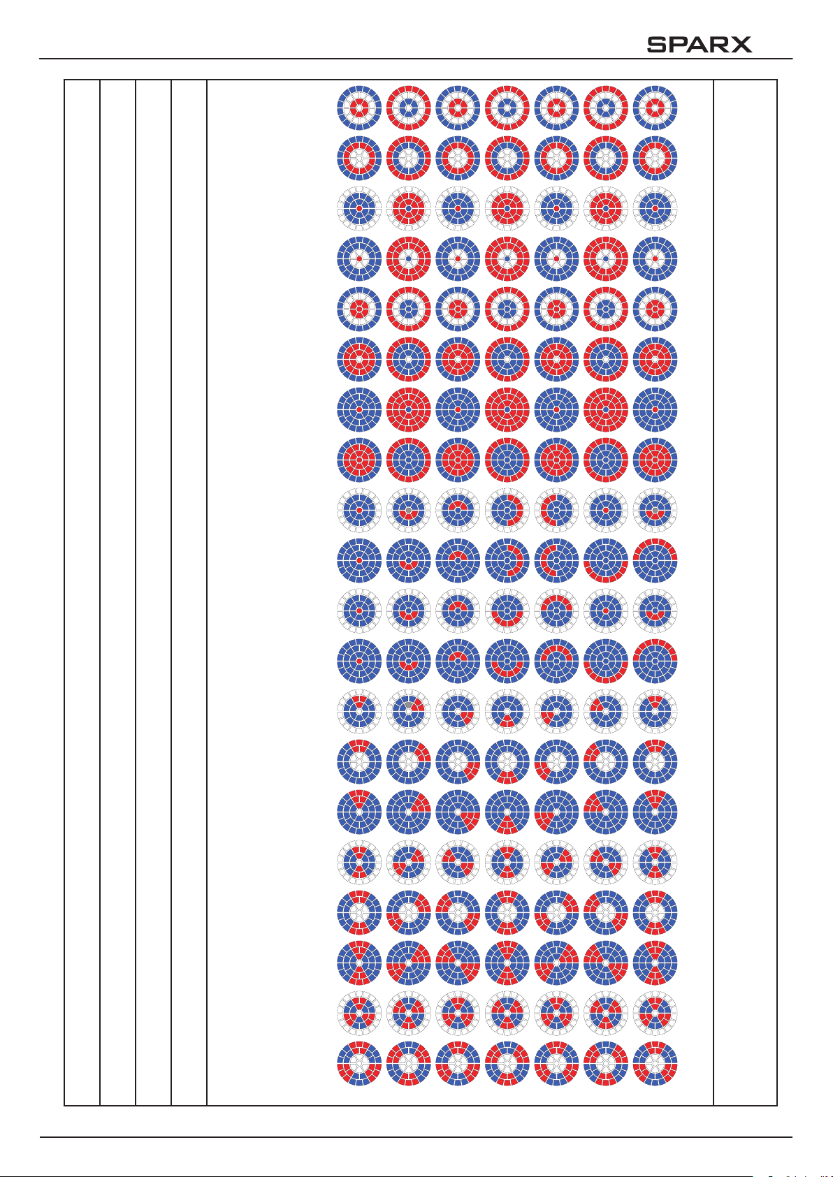
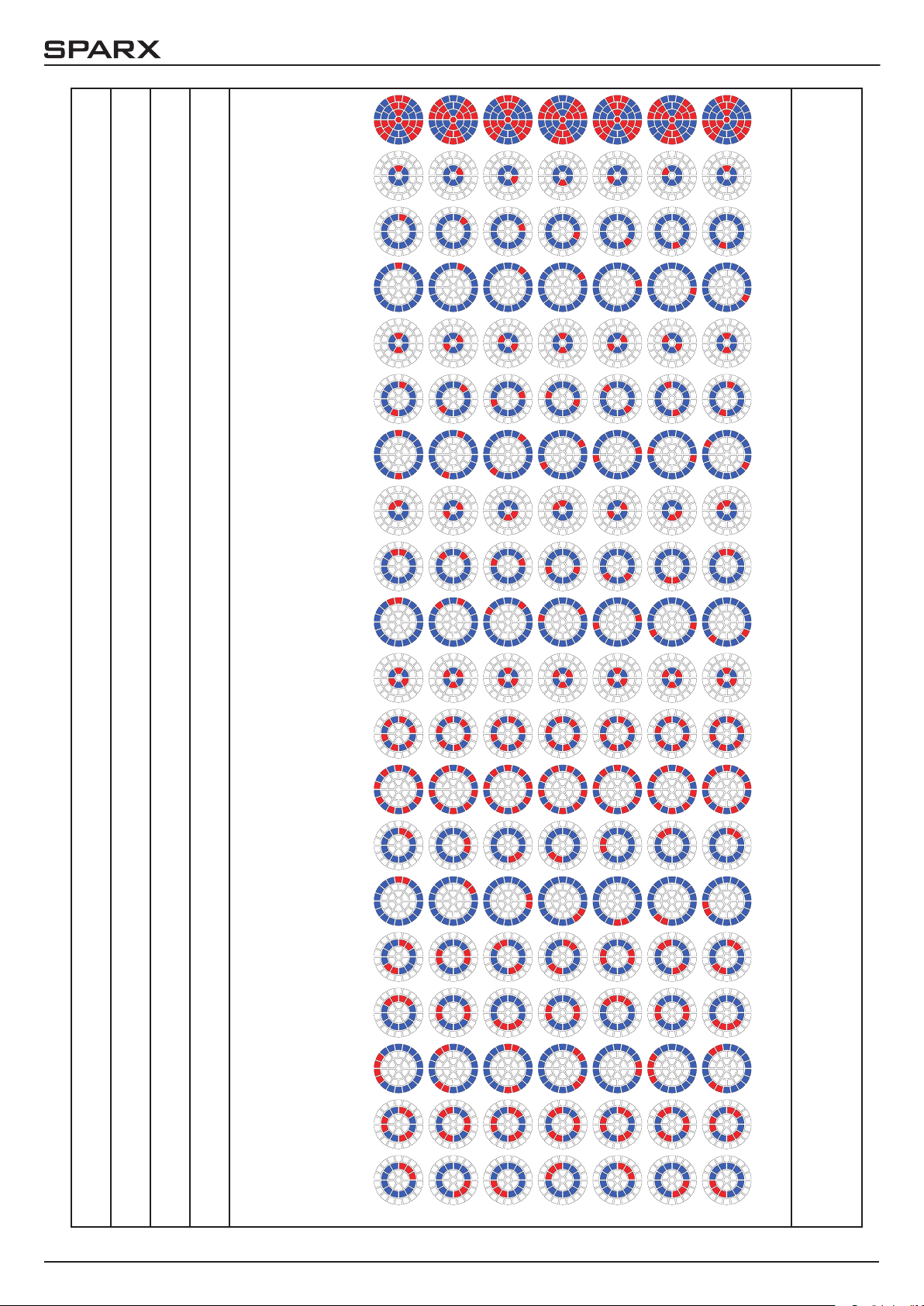
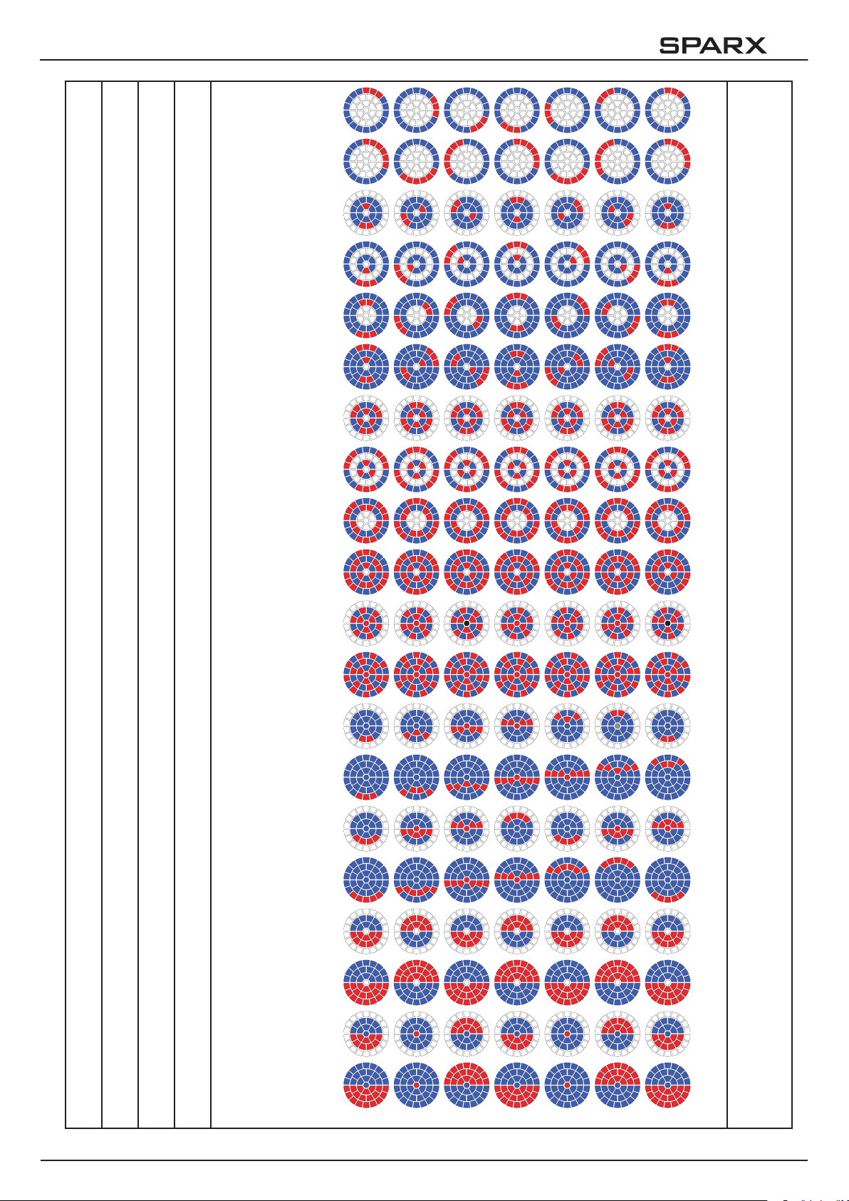
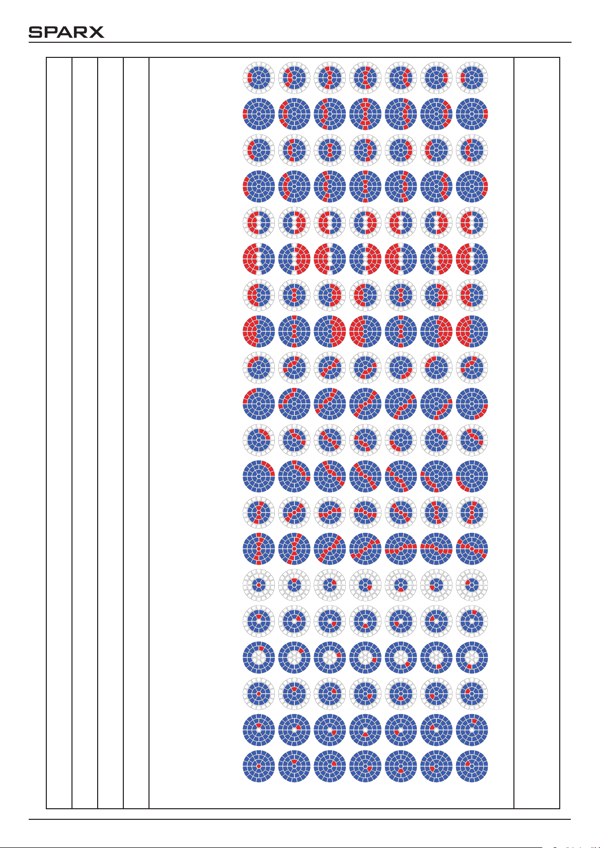
Beispiele zu Anwendung der Kanäle 9-15
In der folgenden Tabelle nden Sie ein paar Muster und Effekte, die Sie als Vorlage verwenden
können um weitere und auch eigenen Effekte zu realisieren.
Mapping
CH09
Pattern
Mode
CH10
Pattern
CH11
Pattern
Speed
CH12
000 001 001 026 000 000 000 000 000 255 255 000 000 000 000
080 000 005 013 000 000 000 000 000 255 255 108 000 000 000
079 128 001 004 000 255 000 000 000 255 255 000 000 000 000
086 004 004 004 000 000 000 000 000 066 255 255 171 000 000
027 001 001 026 000 000 000 000 000 255 255 000 000 000 000
033 129 004 005 255 255 171 000 000 255 255 000 000 000 000
086 006 004 008 000 000 000 000 000 080 255 255 171 000 000
110 012 001 000 000 000 000 000 000 255 255 255 171 000 000
111 012 001 008 000 000 000 000 000 255 255 255 171 000 000
000 000 000 000 000 000 000 255 000 255 000 000 000 201 010
Glow
R
CH21
Glow
G
CH22
Glow
B
CH23
Main
R
CH25
Main
G
CH26
Main
B
CH27
Pattern
R
CH39
Pattern
G
CH30
Pattern
B
CH31
Sparkle
CH14
Sparkle
Speed
CH15
- 31 -
Page 32

10
Kanal 33 (Transition/Crossfade) nur im Mode 4 verfügbar
Durch den Kanal 33 kann zwischen der internen Effektengine und der reellen Einzel-LED-Ansteuerung umgeschaltet bzw. über geblendet werden. Wird auf dem Kanal 33
der DMX-Wert 255 gesendet, so arbeitet der Scheinwerfer
zu 100 % in der Einzel-LED-Ansteuerung. Die folgenden
Kanäle 34-181 dienen hierbei zur Ansteuerung der einzelnen LEDs, jeweils in der Reihenfolge Rot, Grün, Blau,
Weiß. Die folgende Abbildung zeigt die Anordnung der
LED-Gruppen wenn der Scheinwerfer stehend mit den
PAN/TILT-Werten 127/60 angesteuert wird und das Display hierbei in die gleiche Richtung wie die LED‘s zeigt.
25
24
27
26
11
10
23
22
12
9
28
13 14
4
3
8
21
29
5
1
2
20
19
30
6
7
37
15
18
31
16
17
36
32
33
34
35
6. Service
6.1 Servicemenü RESET FIXTURE
Auf den Befehl „Reset“ führt der Sparx10 eine Initialisierung auf seine Startwerte aus. Es ist der
gleiche Vorgang wie nach dem Einschalten des Sparx10. Sollte eine Fehlermeldung im Display
erscheinen könnte dies eine erste Maßnahme sein, diese zu beheben.
ERROR LIST
Der Sparx10 speichert alle auftretenden Fehler intern ab. Eine Fehlermeldung kann eine harmlose Ursache haben. Bei öfters auftretenden Fehlermeldungen sollten Sie unseren Stützpunkthändler kontaktieren. Alle Fehlermeldungen werden mit der jeweiligen Häugkeit angezeigt und
können gelöscht werden.
FUNCTION TEST
Diese Funktion erlaubt Ihnen alle Funktionen des Sparx10 zu testen ohne den Betrieb über ein
Lichtmischpult. Die Pan/Tilt Rückstellung ist dabei deaktiviert.
LED TEST
Der Sparx10 prüft hierbei alle LED´s einzeln auf RGBW Funktionalität. Sollte eine LED defekt sein
wird dies durch eine Fehlermeldung angezeigt.
DMX TEST
Über diesen Menüpunkt lässt sich der DMX-Eingang testen. Wählen Sie über die Funktionstasten den zu testenden DMX Kanal aus. Das Display zeigt den ankommenden Wert an, gleichzeitig
reagiert der Sparx10 entsprechend.
INIT PAN TILT
Der Sparx10 wird ab Werk in der Pan/Tilt Postion kalibriert. Verliert er diese Kalibrierung, d.h. der
Scheinwerfer fährt gegen die Anschläge, bzw. ndet seine Position nicht mehr, oder es musste
die Pan/Tilt-Platine getauscht werden, so kann er über diese Funktion neu initialisiert werden.
Dieser Vorgang dauert ca. 10 Minuten und schließt mit einem Reset ab.
DISPLAY CONTRAST
Bei starker Erwärmung kann sich der Kontrast des LCD Displays verändern. In diesem Menüpunkt lässt sich der Kontrast nachstellen.
- 32 -
Page 33

10
FINE ADJUST
Weißabgleich der Farben
Dieser Weißabgleich wird werksseitig vom Hersteller durchgeführt und muss nur in einzelnen
Sonderfällen angepasst werden. Bedingt durch den Herstellungsprozess, können bei LEDs eines
Typs Helligkeitsunterschiede im direkten Vergleich auffallen. Generell geben alle LED-Hersteller
Bereiche an, in denen ihre Produkte streuen. Das Einteilen in verschieden fein abgestufte Klassen wird als Klasseneinteilung (engl.: Binning) bezeichnet. Die Unterschiede im Binning werden
beim Sparx10 werksseitig durch einen Weißabgleich angepasst. Die Anpassung an einen Referenzscheinwerfer stellt sicher, dass Sparx10 aus unterschiedlichen Produktionszyklen problemlos miteinander betrieben werden können.
Um einen Weißabgleich durchzuführen kann die Helligkeit der Lichtquellen Rot-Grün-Blau-Weiß
einzeln eingestellt werden. Schließen Sie hierzu ein DMX-Pult an den Scheinwerfer an und stellen Sie den Scheinwerfer so ein, dass dieser in einer Entfernung von ca. 8 Meter zur Wand einen
weißen Punkt mit einem Durchmesser von ca. 2-3 Meter macht. Die RGBW-Kanäle müssen
hierzu am Pult jeweils auf DMX 255 stehen!
Wechseln Sie nun am Scheinwerfer in den Menüpunkt SERVICE, FINE ADJUST. Um in den Menüpunkt FINE ADJUST zu gelangen müssen Sie die Tastenkombination „ENTER“ (gedrückt halten)
und „ESC“ drücken. In der folgenden Menüauswahl SKAL RED, SKAL GREEN, SKAL BLUE und
SKALWHITE wird der prozentuale Wert der einzelnen Leuchtstränge eingestellt. Gleichzeitig ändert sich der Farbanteil im Lichtstrahl. Achten Sie darauf das wenigstens ein Farbwert immer auf
100% verbleibt, da sonst die Gesamthelligkeit verringert wird. Diese können Sie unter SKAL ALL
einstellen. Die X/Y Nachregelung des Sparx10 ist hierbei deaktiviert.
Der aktuelle Weißabgleich bleibt auch bei der Rückstellung auf Werkseinstellung (Kapitel 4.2) erhalten. Mit dem Weißabgleich kann das grundsätzliche Verhältnis der RGBW-Kanäle zueinander
verändert werden. Dies beeinusst sowohl den Farbradkanal als auch die RGBW-Kanäle wenn
dies über den Steuerkanal (Kanal 5) eingestellt wird. Sollte z.B. über das FINE ADJUST Menü die
Intensität einer Farbe deutlich verändert worden sein, stimmen die vorab eingestellten Farben
auf dem Farbradkanal nicht mehr.
Zoom
Der Zoombereich wird ab Werk kalibriert. Verliert der Scheinwerfer diese Kalibrierung kann die
Optik des Sparx10 mit dem Offset nachjustiert werden.
RECEIVESOFT
Über diesen Bereich kann die Software des P8 eingespielt werden (siehe 7.3 Software Update)
6.2 Gerät reinigen
!
Sie sollten in regelmäßigen Abständen die Funktion der Lüfter im Kopf und Fuß überprüfen. Vor
allem sollten Sie darauf achten, dass die Lufteinlässe sowie das Innere des Sparx10 frei von
Flusen und Staub sind.
Hierzu öffnen Sie die Lüfter-Abdeckung am Kopf (4x Kreuzschlitzschraube mit Bajonettverschluss) und die Bodenplatte am Fuß. Nun können Sie den Sparx10 mit einem Pinsel und einem
Staubsauger säubern.
ACHTUNG:
Gerät vom Netz trennen und mindestens 10 Minuten abkühlen lassen!
Bei direktem Blick in die Lichtquelle Schweißer-Schutzbrille der Abschwächung 4-5
tragen!
- 33 -
Page 34

10
6.3 Software Update
Der Sparx10 lässt sich über einen PC/Notebook mit Hilfe eines Upgrade-Dongles (USB/
DMX-Converter) über den 5 poligen DMX Eingang updaten. Den Upgrade Dongle mit der dazugehörigen Software erhalten Sie bei unseren Stützpunkt-Händlern.
6.4 Prüfen von elektrischen Betriebsmitteln
Nach DGUV Vorschrift 3 / Vorschrift 4 müssen Elektrische Anlagen und Betriebsmittel einer regelmäßigen Überprüfung unterzogen werden. Als Messpunkt zur Isolations- und Fehlerstrommessung kann hierfür die Befestigungsschraube der DMX 5-pol Buchse verwendet werden. Die
Schraube ist über eine Kontaktscheibe mit allen Blechteilen verbunden.
PE-Messpunkt
- 34 -
Page 35

10
7. Spezifikationen
Maße und Gewicht
Länge ............................................................... 403,8 mm
Breite ............................................................... 264,8 mm
Höhe ............................................................... 480,0 mm
Gewicht netto / brutto ............................................. 12,25 / 14,70 kg
Elektronik
Netzanschluss ............................................. 100-240 V AC, 50-60Hz
Maximale Leistungsaufnahme ............................................. 600,0 VA
Leistungsaufnahme im Standby ............................................ 46,5 VA
Temperatur
Maximale Umgebungstemperatur .............................................40 °C
Minimale Umgebungstemperatur ..............................................5 °C
Optik, Photometrische Daten
Lichtquelle ............................................. 37 RGB LEDs (15W-Klasse)
Lichtstärke ......................... 12200 Lumen (Zoom max.) 9300 Lumen (Zoom min.)
Effekte
Pan ................................................................... 433,6°
Tilt .................................................................... 333,3°
Zoom ..................................................................4°- 40°
Farbtemperatur ........................................CTO, variable 12500K-2500K
Konstruktion
Farbe .................................................................schwarz
Gehäuse ..............................................................PC ABS
Schutzklasse ............................................................. IP 20
Installation
Aufstellungsort .......................................................Innenraum
Aufnahme ......................................................2x Omega Bügel
Position ..................................................................jede
Mindestabstand zu brennbaren Gegenständen ..................................1,0 m
Anschlüsse
Netzeingang .....................................Neutrik PowerCon NAC3MPA (blau)
Netzdurchgang ...................................Neutrik PowerCon NAC3MPB (grau)
DMX in / out USITT DMX512 ...................................5-pin, 3-pin in/out XLR
- 35 -
Page 36

10
8. Konformitätserklärung
Konformitätserklärung
im Sinne der Richtlinie: 2014/35/EU Niederspannungsrichtlinie,
(Richtlinie 2014/35/EU des Europäischen Parlaments und des Rates vom 26.02.2014 zur Angleichung der
Rechtsvorschriften der Mitgliedstaaten betreffend elektrische Betriebsmittel zur
Verwendung innerhalb bestimmter Spannungsgrenzen)
im Sinne der Richtlinie: 2014/30/EU Elektromagnetische Verträglichkeit
(Richtlinie 2014/30/EU des Europäischen Parlaments und des Rates vom 26.02.2014 zur Angleichung der
Rechtsvorschriften der Mitgliedstaaten über die elektromagnetische Verträglichkeit)
Der Hersteller, JB-Lighting Lichtanlagentechnik GmbH
Sallersteigweg 15
89134 Blaustein-Wippingen
erklärt, dass das Produkt: Sparx10
den wesentlichen Schutzanforderungen der Richtlinien entspricht. Es wurden folgende Normen zur Konformitätsbewertung herangezogen:
Aussendung - Anforderungen Einrichtungen der Informationstechnik, Funkstöreigenschaften gemäß EN 55022:2010 Grenzwerte und Messverfahren
Leitungsgeführte Störaussendung Einrichtungen der Informationstechnik, Funkstöreigenschaften -
EN 55022:2010 Grenzwerte und Messverfahren
Abstrahlungen Einrichtungen der Informationstechnik, Funkstöreigenschaften -
EN 55022:2010 Grenzwerte und Messverfahren
Oberschwingungsströme Elektromagnetische Verträglichkeit
EN 61000-3-2:2015 Teil 3-2: Grenzwerte, Prüfung von Oberschwingungsströmen
(für Geräte mit einem Eingangsstrom < 16A pro Phase)
Flicker Elektromagnetische Verträglichkeit (EMV)
EN 61000-3-3:2013 Teil 3-3: Grenzwerte, Begrenzung von Spannungsänderungen,
Spannungsschwankungen und Flicker in Niederspannungsnetzen
(für Geräte mit einem Eingangsstrom < 16A pro Phase)
Störfestigkeit - Anforderungen Elektromagnetische Verträglichkeit (EMV) - Teil 6-2:
gemäß EN 61000-6-2:2005 Fachgrundnorm – Störfestigkeit Industriebereich
EN 61000-4-2:2009 Teil 4-2: Störfestigkeit gegen Entladung statischer Elektrizität
EN 61000-4-3:2006 +A1:2008 +A2:2010 Teil 4-3: Störfestigkeit gegen hochfrequente elektromagnetische Felder
EN 61000-4-4:2012 Teil 4-4: Störfestigkeit gegen schnelle transiente elektrische
Störgrößen (Burst)
EN 61000-4-5:2006 Teil 4-5: Störspannungen gegen Stoßspannungen (Surge)
EN 61000-4-6:2014 Teil 4-6: Störfestigkeit gegen leitungsgeführte Störgrößen,
induziert durch HF
EN 61000-4-8:2010 Teil 4-8: Störfestigkeit gegen Magnetfelder mit energietechnischen
Frequenzen
EN 61000-4-11:2004 Teil 4-11: Störfestigkeit gegen Spannungseinbrüche, Kurzzeit unterbrechungen und Spannungsschwankungen
Blaustein, den 01.11.2014
________________________
Jürgen Braungardt
Geschäftsführer
- 36 -
Page 37

10
- 37 -
Page 38

10
English
Contains also French warnings!
Comprend les avertissements en langue français
- 38 -
Page 39

10
1. Dimensions & product overview
158,9
480
370
340
403,8
303
264,8
- 39 -
Page 40

10
2. Introduction
2.1 Safety instruction
WARNING: This device is for professional use only! Protection rating IP 20 - only
!
!
indoor use
WARNING: LED Radiation - do not look into the beam at a distance of less than
5 meters (197 inches) from the front surface of the product. Do not view the light
output with optical instruments or any device that may concentrate the beam. LED
class 3 according to EN 62471.
WARNING: JB-Lighting Lichtanlagentechnik GmbH does not authorize or warrant
its products for use in life support systems. Life support systems are equipment intended to support or sustain life, and whose failure to perform, when properly used
in accordance with instructions provided, can be reasonably expected to result in
personal injury or death.
This product conforms to the European Community Directives:
- Low voltage directive 2014/35/EU
- Electromagnetic compatibility 2014/30/EU
ATTENTION: Cet appareil ne convient que pour un usage professionnel! Degré de
!
!
2.2 Unpacking
This package contains the Sparx10, two omega brackets with 1/4 turn fasteners, this manual
(one per shipment) as well as a power cable with PowerCon connector (no cable in US model).
Open the top of the box and remove the inlay. Remove the unit from the box. For any damage
occurring during transport, report to the transport company immediately.
protection: IP 20
ATTENTION: Rayonnement LED - Ne pas regarder le faisceau à moins de 5m ou à
l‘aide d‘un instrument à optiques. LED classe 3 selon la norme DIN EN 62471
ATTENTION: JB-Lighting Lichtanlagentechnik GmbH n‘autorise pas l‘utilisation
de leurs appareils dans des systèmes ou dispositifs permettant le maintient en vie.
Sont considère systèmes ou dispositifs de maintient en vie tous systèmes qui ont
pour but de maintenir la vie ou de la stabilisée et qu‘un défaut ou défaillance éventuelle de celui-ci ne blesse ou entraine la mort d‘autrui.
Le produit décrit dans ce manuel est conforme aux directives Européennes suivantes:
- Directive appliquée à la Basse Tension 2014/35/EU
- Directive CEM 2014/30/EU
3. Installation
3.1 Connection to Mains
WARNING: To ensure proper installation of the plug consult a qualied technician!
!
- 40 -
ATTENTION: Installation de la connexion au réseau doit être effectuée par un professionnel!
Page 41

10
The Sparx10 is supplied with a power cable with a Neutrik PowerCon connector. Install a 3-prong
grounding type plug that ts your supply. US model comes without power cable and connectors.
Required cable type see 4.5. Connected load: voltage 100-240 V, frequency 50 - 60 Hz
Connection EU-model:
Color Function Symbol
brown Live „L“
blue Neutral „N“
green/yellow Ground
Connection non EU-model:
The Sparx10 may only be connected to mains supply systems according to this drawing:
mains
2 conductor
1 phase
3 conductor
1 phase
4 conductor
3 phase
3.2 Rigging the fixture
WARNING: Keep xtures at least 1,0 meter away from inammable articles! Always
use a safety cable attached to the base!
L
N
L
N
L
L
L
L
N
1
2
3
!
ATTENTION: Respecter une distance minimale de 1,0 m entre le projecteur est
d‘éventuelles objets inammables! Sécuriser toujours le Sparx10 avec une élingue
de sécurité appropriée!
Sparx10
L
N
PE
L
PE
N
L
N
PE
WARNING: only can be used in
Canadian mains supply system
with 2 conductor, 1 phase with
max. 120V!
!
ATTENTION: Le A8 peut être utilisé au Canada avec 2 conducteurs, 1 phase et une tension
maximal de 120V!
The Sparx10 can either be placed on the oor or hang on
a trussing system in any position. When placing the unit
on the oor make sure that it stands on rigid ground, because the air inlets in the base must not be covered with
anything! To mount the unit on a trussing system use two
of the original JB-Lighting omega brackets with Camloc-connectors. The Camlocs must snap in to be locked
properly. Always attach a safety cable to secure the unit.
140
140
224
- 41 -
Page 42

10
3.3 DMX wiring
Use a shielded twisted-pair cable with two pairs to connect the serial link. Connect all pins if
you want to upgrade the software in cross-load. If a microphone cable (or any other cable with
only one pair) is used the software can not be updated via DMX line because pin 4 and 5 are not
connected.
Pin assignment:
Pin 1 = shield
Pin 2 = data -
Pin 3 = data +
Pin 4 = data out Pin 5 = data out +
The Sparx10 has 3pin and 5pin XLR connectors for DMX-in and DMX-out. Do not connect more
than one data input and one data output on a xture.
Connect the DMX-out of the control desk to the rst Sparx10 in line. (lighting control desk DMX-Out
-> Sparx10 DMX-in). Connect the second Sparx10 to the rst in line, and so on (Sparx10 no. 2 DMX-In
-> Sparx10 no. 1 DMX-Out). All 3-pin and 5-pin connectors are wired parallel. Do not use this xture
as a DMX splitter! The DMX-Out of the last unit in line is not occupied unless problems occur. Then
use a termination plug with the last Sparx10 in line. (XLR-connector with a 120 Ohm resistor soldered
between pin 2 and pin 3). Problems might occur when the line is overloaded, e.g.
3.4 Installing a plug on the power cord
Install a plug like described in chapter 3.1.
Connected load: Voltage 100-240 Volts, frequency 50 - 60 Hz, power max. 600 VA. Connect the
xture to a proper installed grounded system only. If any doubts on the electrical installations
occur, consult a qualied electrician. In case of damages occurring due to a not proper installed
electrical system, warranty claims will be invalidated. Don´t use xtures when top cover is not
xed properly. Contact with electronic parts can result in risk for life. (Electrical shock 100-240 V)
3
1
2
4
5
shielded signal cable
1
2
3
4
5
Connect xture only after assuring that the electrical installation ts your demands. If any doubts
occur consult a qualied technician!
WARNING: Sparx10 might light up immediately if standalone mode is active or DMX
signal is connected!
!
ATTENTION: Le projecteur Sparx10 peut s’illumine directement, lorsque le mode
standalone et activé ou si un signal DMX est programmé!
3.5 Relaying power to other fixtures
WARNING: To ensure proper installation of the plug consult a qualied technician!
!
Power can be relayed to another device via the grey PowerCon throughput socket that accepts
a grey PowerCon NAC3FCB cable connector. Note that blue input and grey throughput connectors have different design: one type cannot be connected to the other.
ATTENTION: Installation de la connexion au réseau doit être effectuée par un professionnel!
- 42 -
Page 43

10
The value of Sparx10 in chain depends on the local power network. Never use more than ve in
one line. Power throughput cable must be rated 20A min., have three conductors 1,5mm² min.
conductor size and a outer cable diameter of 5-15mm. Use only original PowerCon plug from
Neutrik. See installation manual from manufacturer (www.neutrik.com).
Color Function Symbol
brown Live „L“
blue Neutral „N“
green/yellow Ground
4. Control panel
The Sparx10 is equipped with a backlit graphic display, which can be rotated through 180 deg.
if the unit is installed upside down.
Rotating the display
Use the centred button to change the orientation of the display. To adjust the personal setting of
the Sparx10 use keys located on the control panel. Functions see menu on the following page.
The Sparx10 can be addressed in the main menu. For addressing in a case, the reset can be
aborted by pressing the right base button during powering the xture. The main menu also informs about the DMX-mode. If wireless DMX is used, the eld intensity from the sender will be
displayed. Press „ENTER“ to enter a menu, select a function or apply a selection. Press keys
„DOWN“ and „UP“ to scroll within a menu or set values. To escape a function press key „ESC“.
A few functions can be entered or recalled by means of a combination of two keys. For example
FINE ADJUST at menu SERVICE and MODIFY, RUN and REMOTE at menu STANDALONE. To
enter these functions press „ENTER”, keep it down and press “ESC” in addition. To leave the
menu press „ESC“ hold it down and press „Enter“, MODIFY and FINE ADJUST you can leave
only by pressing „ESC“.
The main menu can be locked to avoid an accidental change of the conguration. To lock press
“ENTER” and keep it down and press “ESC” in addition. To unlock press „ESC“ (keep it down)
and press „ENTER“ in addition.
Special functions are assigned to the display lighting:
The display is not illuminated during reset. Slow ashing of the display illumination means no
DMX signal is connected. Fast ashing of the display illumination showing „JB-Lighting“ means
a failure was reported and stored in the ERROR LIST (To clear - see menu navigation on next
page). Fast ashing of the display illumination showing an error message means an current failure is reported, e. g. *PAN TIMEOUT - please contact your dealer or our service department. If
the Sparx10 receives a DMX-signal the display illumination dims out after 30 seconds in order
not to irritated during standard operation.
- 43 -
Page 44

10
4.1 Menu navigation
ENTER
FACTORY DEF. LOAD DEFAULTS SURE?
UP
DMX ADDRESS ADDRESS +/-
ENTER ENTER
LOAD DEFAULTS SURE?
SAVE DEFAULTS SURE? PASSWORD
PERSONALITY
DMX INPUT MODE WIRED
WIRED/WIRELESS
DMX MODE MODE 1
MODE 2
MODE 3
MODE 4
PAN / TILT RESOLUTION
PAN INVERS
TILT INVERS
PAN/TILT SWAP
CURVES DIMMER CURVE SQUARE
RGB CURVE SQUARE
SHORTEST DIST. ON
OFF
CAMERA MODE 50 Hz
60 Hz
FLEX
COOLING MODE STANDARD
SILENT
HIGH-POWER
WLJB DMX HOLD FADE OUT
DMX HOLD
16 BIT
8 BIT
NORMAL
INVERS
NORMAL
INVERS
NORMAL
INVERS
LINEAR
LINEAR
SERVICE
RESET FIXTURE SURE?
ERROR LIST LIST
CLEAR
FUNCTION TEST START TEST
LED TEST START TEST TEST RUNNING
DMX TEST DMX CHANNEL CH 001: --- +/-
INIT PAN/TILT
DISPLAY CONTR. D. CONTR: +000 +/-
FINE ADJUST
RECEIVE SOFTW. SURE?
SURE?
SKAL RED
SKAL GREEN
SKAL BLUE
SKAL WHITE
SKAL ALL
OFS ZOOM
PAN TIMEOUT COUNT: 1 CLEAR?
SURE?
TEST RUNNING
- 44 -
Page 45

10
STANDALONE
EDIT STEP NR. +/-
RUN
TIMEBASE 1 SEC
1/10 SEC
REMOTE
MODIFY
CAPT DMX
INSERT
DELETE
RESET STEP
CLEAR ALL
FADE TIME FADE TIME +/-
NEXT TIME NEXT TIME +/-
PAN PAN +/-
TILT TILT +/-
CONTROL CONTROL +/-
SHUTTER SHUTTER +/-
DIMMER DIMMER +/-
ZOOM ZOOM +/-
MAPPING MAPPING +/-
PATTERN MODE PATT. MODE +/-
PATTERN PATTERN +/-
PATTERN SPEED PATTERN SP. +/-
COLOR SPREAD COL. SPREAD +/-
SPARKLE SPARKLE +/-
SPARKLE SPEED SPARKLE SP. +/-
CTC 3200K
COLOR
SPEED PAN/TILT
SPEED EFFEKT
MOVE BLACKOUT
RED GLOW
GREEN GLOW
BLUE GLOW
WHITE GLOW
RED
GREEN
BLUE
WHITE
RED PATTERN
GREEN PATTERN
BLUE PATTERN
WHITE PATTERN
CTC 3200K +/-
COLOR +/-
SPEED P/T +/-
SPEED EFFEKT +/-
MOVE BO. +/-
RED GLOW +/-
GREEN GLOW +/-
BLUE GLOW +/-
WHITE GLOW +/-
RED +/-
GREEN +/-
BLUE +/-
WHITE +/-
RED PATTERN +/-
GREEN PATT. +/-
BLUE PATTERN +/-
WHITE PATT. +/-
INFO
SOFTWARE VER.
FIRMWARE VER.
TOT OPERAT. TIME
TEMP BASE LCD ACTUAL
MAX RESET?
TEMP BASE PS ACTUAL
MAX RESET?
TEMP HEAD DRV ACTUAL
MAX RESET?
TEMP HEAD LED ACTUAL
MAX RESET?
TEMP HEAD LEDS
- 45 -
Page 46

10
4.2 FACTORY DEFAULTS
To set back the Sparx10 to factory defaults choose in the menu FACTORY DEFAULT -> LOAD
DEFAULTS. After conrming SURE? with ENTER, the personal settings of the Sparx10 will be
set back to factory defaults.
If the white balance was adjusted before, it will be not affected by the set back to factory defaults.
4.3 USER DEFAULTS
If personal settings are done in the PERSONALITY menu, the user can save and reload it in the
USER DEFAULTS menu. To make sure that the personal settings are not changed quickly on a
stage, the save progress is locked with the password „JB-LIGHTING“.
4.4 DMX ADDRESS
Change the DMX address directly by pressing the keys „UP“ and „DOWN“. Conrm and store it
by pressing key „ENTER“. The DMX address can also be changed in the menu DMX ADDRESS.
4.5 PERSONALITY DMX INPUT MODE
The Sparx10 provides an embedded radio-DMX receiver. The receiver works with the
JB-Lighting Wireless TRX transmitter. To enable the Sparx10 to receive radio-DMX change the
menu from WIRED (factory default) to WIRED/WIRELESS. The xture needs to be logged in to
the Wireless TRX transmitter. To log-in press the „Start“ button (see also manual Wireless TRX).
The radio channel is displayed when the Sparx10 is logged. The main display will show the intensity of the incoming signal. If the Sparx10 is connected either via DMX cable and radio-DMX,
the cable signal has priority.
DMX MODE
The Sparx10 offers 3 different operating modes (see DMX protocol page 40). Mode 1 is an 8 bit
mode with which you can control all features of your Sparx10. For using the full range of DMX
channels use the mode 2 - 16 BIT. Use this mode for smoother operation with the RGBW channels. In order to operate the Sparx10 with less DMX channels the DMX mode can be set to mode
3. In this mode there are all channels in 8 bit mode without Pan/Tilt.
PAN / TILT
RESOLUTION sets pan and tilt to 8 bit or 16 bit control resolution. The default setting is 16 bit.
If this ne resolution is not required, you can set to 8 bit for quicker operation of pan/tilt values.
The PAN INVERS and TILT INVERS commands invert the direction of pan and tilt. The PAN/TILT
SWAP command sets pan commands to tilt and vice versa.
CURVES
Dimming curves can be adjusted for the dimmer channel and the RGBW channels. There is a
square-law curve for ner control at low intensity and coarser control at high intensity and a linear-law curve available.
SHORTEST DISTANCE
This setting is only for the color wheel channel. Switched to ON (default) it always take the shortest route from one colour to another in order to simulate a physical color wheel. Switched to OFF
it routes only from white to turquoise and backwards.
CAMERA MODE
For icker free recording in TV-studios the Sparx10 offers three different modes from 50 Hertz
(PAL, Secam) to 60 Hertz (NTSC). Flex mode is designed, if cameras have a refresh frequency that makes the 50 or 60Hz settings ineffective. Factory default is 60Hz. Access the menu
PERSONALITY -> CAMERA MODE and choose the required frequency. To conrm press
“ENTER”. This can be also controlled with the control channel (channel 5) via lighting desk.
- 46 -
Page 47

10
COOLING MODE
The Sparx10 offers three different modes for fan operation. The default setting STANDARD will
suit most applications. Switch to SILENT to reduce the speed of the fans to a minimum. This
mode is to be used only a well ventilated rooms with low ambient temperature, with reduced light
output or if the xture is only required occasionally. The HI POWER mode is designed to be used
in areas with higher air temperature or for xed installations. The fans start to run faster with more
airow which produces more noise.
There is in no mode danger for the lifetime of the Sparx10. If the temperature rise to much the
xture switches off automatically.
WLJB DMX HOLD
The behaviour of the Sparx10 in case the wireless DMX connection is interrupted can be set to:
1. DMX Hold - Sparx10 freezes on the last received DMX value.
2. Fade out - Sparx10 fades out after 5 seconds.
When DMX signal is back the Sparx10 rst turn to its new position and fades in.
4.6 STANDALONE mode
A sequence, up to 20 steps, consisting of preprogrammed cues can be recalled by means of
the STANDALONE MODE. The sequence will run as a loop. Cues can be entered in two different
ways. The rst way is to program every feature by means of the key of the units on-board control
panel. The second way is to program the cues by means of a connected DMX control console
and to store them in the xture.
IMPORTANT! The functions MODIFY, RUN and REMOTE can be accessed only by pressing a
combination of keys and not just by pressing „ENTER“. Before activating the functions make
sure that there is just one DMX-transmitter in the DMX-line (e.g. one control console or one master xture). A number of DMX-transmitters can damage the DMX driver of the xtures. To enter
the functions press “ENTER” (keep it down) and press „ESC“ in addition.
Programming the stand alone sequence:
Enter the menu STANDALONE -> EDIT. STEP NR 01/01 will be displayed. Enter the MODIFY
menu to get access to the xtures functions. Recall the functions and enter DMX values. Enter
FADE TIME (during which the effects will move to the programmed position) Enter NEXT TIME
which will be the duration of the step. Add a new step with INSERT. The DMX values of the last
step will be automatically copied to the new step. With DELETE one step of the sequence can
be deleted. Choose the step and conrm the function with ENTER. To reset the DMX values of a
step use RESET STEP. Select the step and conrm with “ENTER”. All DMX values of the step will
be set to zero. With CLEAR ALL the complete sequence will be deleted and the display will show
STEP 01/01
Store cues from a DMX controller:
The DMX values can also be programmed by means of a DMX console. Enter the STANDALONE
menu and navigate to CAPT DMX. Program the DMX values with an external DMX console. To
capture the data press „ENTER“. The xtures display will show START CAPTURE. To insert, delete or reset use the keys of the control panel of the xture.
Activate the standalone mode:
The standalone mode is activated in the menu STANDALONE -> RUN. To enter the functions
press “ENTER” (keep it down) and press “ESC” in addition. Sparx10 will execute sequence in a
repeating loop. To leave press “ESC” and hold it down and press “ENTER” in addition.
- 47 -
Page 48

10
Operation in Master-Slave mode:
To set a xture to slave-mode navigate to REMOTE. To activate the slave function press “ENTER”
(keep it down) and press “ESC” in addition. The display will show either REMOTE INACTIVE if no
DMX-signal is being received or REMOTE ACTIVE if a DMX-signal is being received. To leave this
function press “ESC” (keep it down) and press “ENTER” in addition. Connect the Sparx10 with
DMX cables. Select STANDALONE -> RUN with the master xture. Start function by pressing
“ENTER” (keep it down) and pressing “ESC” in addition. All connected xtures will repeat the
steps synchronized to the master xture. To leave the menu press “ESC” (keep it down) and press
“ENTER” in addition. If you realize that a xture reacts inaccurate check if the display shows
REMOTE ACTIVE.
Pre-load Demo:
The Sparx10 provides 20 pre-programmed Effects in the Pre-load demo menu. The user can
load it an change the values with MODIFY. A quick introducing in the effects of Sparx10 can be
done.
4.7 INFO
The menu informs about the current software/rmware version. The non-resettable TOT OPERATE TIME counter displays total hours of use since the Sparx10 was manufactured.
Temperature readouts from the display panel (TEMP BASE LCD) and power supply unit (TEMP
BASE PS) in the base as well as the driver (TEMP HEAD DRV) and LED PCB (TEMP HEAD LED)
in the head are available. In each case, you can view the current temperature and the maximum
temperature reached since the readout was last reset individually. The TEMP HEAD LEDs views
the actual temperature of the single LEDs.
- 48 -
Page 49

10
5. DMX protocol
The Sparx10 offers 4 different channel modes. The mode can be set in menu item PERSONALITY -> DMX MODE. The used mode will be displayed in the main menu.
Mode 1 (M1) Mode 2 (M2) Mode 3 (M3) Mode 4 (M4)
Channel 1 Pan Pan Pan Pan
Channel 2 Pan ne Pan ne Pan ne Pan ne
Channel 3 Tilt Tilt Tilt Tilt
Channel 4 Tilt ne Tilt ne Tilt ne Tilt ne
Channel 5 Control Control Control Control
Channel 6 Shutter Shutter Shutter Shutter
Channel 7 Dimmer Dimmer Dimmer Dimmer
Channel 8 Zoom Zoom Zoom Zoom
Channel 9 Mapping Mapping Mapping Mapping
Channel 10 Pattern mode Pattern mode Pattern mode Pattern mode
Channel 11 Pattern Pattern Pattern Pattern
Channel 12 Pattern speed Pattern speed Pattern speed Pattern speed
Channel 13 Color spread Color spread Color spread Color spread
Channel 14 Sparkle Sparkle Sparkle Sparkle
Channel 15 Sparkle speed Sparkle speed Sparkle speed Sparkle speed
Channel 16 CTC 3200K CTC 3200K CTC 3200K CTC 3200K
Channel 17 Fixed colors Fixed colors Fixed colors Fixed colors
Channel 18 Pan/Tilt speed Pan/Tilt speed Pan/Tilt speed Pan/Tilt speed
Channel 19 Effect speed Effect speed Effect speed Effect speed
Channel 20 Blackout move Blackout move Blackout move Blackout move
Channel 21 Red Red Red Red
Channel 22 Green Red ne Green Green
Channel 23 Blue Green Blue Blue
Channel 24 White Green ne White White
Channel 25 Red Blue Red
Channel 26 Green Blue ne Green
Channel 27 Blue White Blue
Channel 28 White White ne White
Channel 29 Red Red Red
Channel 30 Green Red ne Green
Channel 31 Blue Green Blue
Channel 32 White Green ne White
Channel 33 Blue Transition / crossfade
Channel 34 Blue ne Red (LED group 1)
Channel 35 White Green (LED group 1)
Channel 36 White ne Blue (LED group 1)
Channel 37 Red White (LED group 1)
Channel 38 Red ne Red (LED group 2)
Channel 39 Green Green (LED group 2)
Channel 40 Green ne Blue (LED group 2)
Channel 41 Blue White (LED group 2)
Channel 42 Blue ne Red (LED group 3)
Channel 43 White Green (LED group 3)
Channel 44 White ne Blue (LED group 3)
Channel 45 White (LED group 3)
Glow RGBW
}
Main RGBW
}
Pattern RGBW
}
}
}
}
Glow RGBWMain RGBWPattern RGBW
Glow RGBW
}
Main RGBW
}
Pattern RGBW
}
- 49 -
Page 50

10
Mode 1 (M1) Mode 2 (M2) Mode 3 (M3) Mode 4 (M4)
Channel 46 Red (LED group 4)
Channel 47 Green (LED group 4)
Channel 48 Blue (LED group 4)
Channel 49 White (LED group 4)
Channel 50 Red (LED group 5)
Channel 51 Green (LED group 5)
Channel 52 Blue (LED group 5)
Channel 53 White (LED group 5)
Channel 54 Red (LED group 6)
Channel 55 Green (LED group 6)
Channel 56 Blue (LED group 6)
Channel 57 White (LED group 6)
Channel 58 Red (LED group 7)
Channel 59 Green (LED group 7)
Channel 60 Blue (LED group 7)
Channel 61 White (LED group 7)
Channel 62 Red (LED group 8)
Channel 63 Green (LED group 8)
Channel 64 Blue (LED group 8)
Channel 65 White (LED group 8)
l l
l l
l l
l l
l l
l l
l l
l l
Channel 134 Red (LED group 26)
Channel 135 Green (LED group 26)
Channel 136 Blue (LED group 26)
Channel 137 White (LED group 26)
Channel 138 Red (LED group 27)
Channel 139 Green (LED group 27)
Channel 140 Blue (LED group 27)
Channel 141 White (LED group 27)
Channel 142 Red (LED group 28)
Channel 143 Green (LED group 28)
Channel 144 Blue (LED group 28)
Channel 145 White (LED group 28)
Channel 146 Red (LED group 29)
Channel 147 Green (LED group 29)
Channel 148 Blue (LED group 29)
Channel 149 White (LED group 29)
Channel 150 Red (LED group 30)
Channel 151 Green (LED group 30)
Channel 152 Blue (LED group 30)
Channel 153 White (LED group 30)
- 50 -
Page 51

10
Mode 1 (M1) Mode 2 (M2) Mode 3 (M3) Mode 4 (M4)
Channel 154 Red (LED group 31)
Channel 155 Green (LED group 31)
Channel 156 Blue (LED group 31)
Channel 157 White (LED group 31)
Channel 158 Red (LED group 32)
Channel 159 Green (LED group 32)
Channel 160 Blue (LED group 32)
Channel 161 White (LED group 32)
Channel 162 Red (LED group 33)
Channel 163 Green (LED group 33)
Channel 164 Blue (LED group 33)
Channel 165 White (LED group 33)
Channel 166 Red (LED group 34)
Channel 167 Green (LED group 34)
Channel 168 Blue (LED group 34)
Channel 169 White (LED group 34)
Channel 170 Red (LED group 35)
Channel 171 Green (LED group 35)
Channel 172 Blue (LED group 35)
Channel 173 White (LED group 35)
Channel 174 Red (LED group 36)
Channel 175 Green (LED group 36)
Channel 176 Blue (LED group 36)
Channel 177 White (LED group 36)
Channel 178 Red (LED group 37)
Channel 179 Green (LED group 37)
Channel 180 Blue (LED group 37)
Channel 181 White (LED group 37)
25
24
26
23
27
11
10
22
12
9
28
13 14
4
3
8
21
29
5
1
2
20
19
30
6
7
37
15
18
31
16
17
36
32
35
33
34
The Pan/Tilt values are at
127/60. The display of the
xture is looking in the same
direction like the LED’s
- 51 -
Page 52

10
M1 M2 M3 M4 Function DMX
1 1 1 1 Pan (X) movement 433,6° 000-255
2 2 2 2 Pan (X) ne 000-255
3 3 3 3 Tilt (Y) movement 333,3° 000-255
4 4 4 4 Tilt (Y) ne 000-255
5 5 5 5 Control
Full output power on LEDs
Fade out with fader (slow - fast)
Basic adjustment RGB
Fade out with fader (slow - fast)
White balance RGB (same white as xed colors color 0)
Fade out with fader (slow - fast)
Color balance for color picker function
Fade out with fader (slow - fast)
}
Lighting
desk
mode1
(reaction time
fast)
000-007
008-015
016-023
024-031
Full output power on LEDs
Fade out with fader (slow - fast)
Basic adjustment RGB
Fade out with fader (slow - fast)
White balance RGB (same white as xed colors color 0)
Fade out with fader (slow - fast)
Color balance for color picker function
Fade out with fader (slow - fast)
Full output power on LEDs
Fade out with fader (slow - fast)
Basic adjustment RGB
Fade out with fader (slow - fast)
White balance RGB (same white as xed colors color 0)
Fade out with fader (slow - fast)
Color balance for color picker function
Fade out with fader (slow - fast)
Full output power on LEDs
Fade out with fader (slow - fast)
Basic adjustment RGB
Fade out with fader (slow - fast)
White balance RGB (same white as xed colors color 0)
Fade out with fader (slow - fast)
Color balance for color picker function
Fade out with fader (slow - fast)
}
}
}
Lighting
desk
mode 2
Lighting
desk
mode 3
Lighting
desk
mode 4
032-039
040-047
048-055
056-063
064-071
072-079
080-087
088-095
096-103
104-111
112-119
120-127
- 52 -
Full output power on LEDs
Fade out with fader (slow - fast)
Basic adjustment RGB
Fade out with fader (slow - fast)
White balance RGB (same white as xed colors color 0)
Fade out with fader (slow - fast)
Color balance for color picker function
Fade out with fader (slow - fast)
}
Lighting
desk
mode 5
(reaction time
slow)
128-135
136-143
144-151
152-159
Page 53

10
Safe
Camera mode, 50Hz (after 2 seconds)
Camera mode, 60Hz (after 2 seconds)
Camera mode, FLEX (after 2 seconds)
Safe
Reset (after 2 seconds)
Safe
6 6 6 6 Shutter
Shutter closed
Shutter open
Shutter pulse opening >10Hz (0,6 sec - 4,8 sec)
Shutter open
Fade effect with dimmer (slow - fast)
Shutter open
Shutter closed
Shutter pulse opening <10Hz (0,6 sec - 4,8 sec)
Shutter open
Shutter pulse closing (0,6 sec - 4,8 sec)
Shutter closed
Shutter fade, 0% (0,6 sec - 4,8 sec)
Shutter open
Shutter fade, 100% (0,6 sec - 4,8 sec)
Shutter closed
Shutter random 100% (0,6 sec - 4,8 sec)
Shutter open
Shutter random 0% (0,6 sec - 4,8 sec)
Shutter closed
Shutter random fade 0% (0,6 sec - 4,8 sec)
Shutter open
Shutter random fade 100% (0,6 sec - 4,8 sec)
Shutter open
160-207
208-215
216-223
224-231
232-239
240-247
248-255
000-015
016-095
096-110
111-111
112-125
126-126
127-126
128-142
143-143
144-158
159-159
160-174
175-175
176-190
191-191
192-206
207-207
208-222
223-223
224-238
239-239
240-254
255-255
7 7 7 7 Dimmer 0 - 100% 000-255
8 8 8 8 Zoom 0-100% (narrow 4° - wide 40°) 000-255
9 9 9 9 Mapping - segment
selection
No mapping, pattern circular
Segment 01
Segment 02
Segment 03
Segment 04
Segment 05
Segment 06
Background color (blue) - RGBW Main
Foreground color (red) - RGBW Pattern
Not active (white) - resp. RGBW Glow
000-000
001-001
002-002
003-003
004-004
005-005
006-006
- 53 -
Page 54

10
Segment 07
007-007
Segment 08
Segment 09
Segment 10
Segment 11
Segment 12
Segment 13
Segment 14
Segment 15
Segment 16
008-008
009-009
010-010
011-011
012-012
013-013
014-014
015-015
016-016
Segment 17
Segment 18
Segment 19
Segment 20
Segment 21
Segment 22
Segment 23
Segment 24
Segment 25
017-017
018-018
019-019
020-020
021-021
022-022
023-023
024-024
025-025
- 54 -
Segment 26
026-026
Page 55

10
Segment 27
027-027
Segment 28
Segment 29
Segment 30
Segment 31
Segment 32
Segment 33
Segment 34
Segment 35
Segment 36
028-028
029-029
030-030
031-031
032-032
033-033
034-034
035-035
036-036
Segment 37
Segment 38
Segment 39
Segment 40
Segment 41
Segment 42
Segment 43
Segment 44
Segment 45
037-037
038-038
039-039
040-040
041-041
042-042
043-043
044-044
045-045
Segment 46
046-046
- 55 -
Page 56

10
Segment 47
047-047
Segment 48
Segment 49
Segment 50
Segment 51
Segment 52
Segment 53
Segment 54
Segment 55
Segment 56
048-048
049-049
050-050
051-051
052-052
053-053
054-054
055-055
056-056
Segment 57
Segment 58
Segment 59
Segment 60
Segment 61
Segment 62
Segment 63
Segment 64
Segment 65
057-057
058-058
059-059
060-060
061-061
062-062
063-063
064-064
065-065
- 56 -
Segment 66
066-066
Page 57

10
Segment 67
067-067
Segment 68
Segment 69
Segment 70
Segment 71
Segment 72
Segment 73
Segment 74
Segment 75
Segment 76
068-068
069-069
070-070
071-071
072-072
073-073
074-074
075-075
076-076
Segment 77
Segment 78
Segment 79
Segment 80
Segment 81
Segment 82
Segment 83
Segment 84
Segment 85
077-077
078-078
079-079
080-080
081-081
082-082
083-083
084-084
085-085
Segment 86
Not used
086-086
087-099
- 57 -
Page 58

10
Numerary 0-4
100-104
Numerary 5-9
Smiley small
Smiley big
Not used
Static segment 1
Static segment 2
Static segment 3
Static segment 4
Static segment 5
105-109
110-110
111-111
112-219
220-220
221-221
222-222
223-223
224-224
Static segment 6
Static segment 7
Static segment 8
Static segment 8
Static segment 10
Static segment 11
Not used
10 10 10 10 Pattern mode
Block 0-31: RGBW LED‘s of the inactive segment are deactivated.
Pattern faded
Pattern switch
Pattern switch with cross fade clockwise
Pattern switch with cross fade anti clockwise
Pixel random ash fast
Pixel random snap open / ramp close
Pixel random ash slow
Pixel random ramp open / snap close
}
regular
interval
225-225
226-226
227-227
228-228
229-229
230-230
231-255
000-000
001-001
002-002
003-003
004-004
005-005
006-006
007-007
- 58 -
Page 59

10
Pixel random ash fast
}
}
}
}
}
}
}
}
random
interval
regular
interval
random
interval
regular
interval
random
interval
regular
interval
random
interval
regular
interval
Pixel random snap open / ramp close
Pixel random ash slow
Pixel random ramp open / snap close
Static effects
Block 32-63: RGBW LED‘s of the inactive segment illuminate in foreground (pattern) color
Pattern faded
Pattern switch
Pattern switch with cross fade clockwise
Pattern switch with cross fade anti clockwise
Pixel random ash fast
Pixel random snap open / ramp close
Pixel random ash slow
Pixel random ramp open / snap close
Pixel random ash fast
Pixel random snap open / ramp close
Pixel random ash slow
Pixel random ramp open / snap close
Static effects
Block 64-95: RGBW LED‘s of the inactive segment illuminate in background (main) color
Pattern faded
Pattern switch
Pattern switch with cross fade clockwise
Pattern switch with cross fade anti clockwise
Pixel random ash fast
Pixel random snap open / ramp close
Pixel random ash slow
Pixel random ramp open / snap close
Pixel random ash fast
Pixel random snap open / ramp close
Pixel random ash slow
Pixel random ramp open / snap close
Static effects
Block 96-127: RGBW LED‘s of the inactive segment illuminate in Glow
RGBW color. Glow RGBW overlays also the active LEDs.
Pattern faded
Pattern switch
Pattern switch with cross fade clockwise
Pattern switch with cross fade anti clockwise
Pixel random ash fast
Pixel random snap open / ramp close
Pixel random ash slow
Pixel random ramp open / snap close
Pixel random ash fast
Pixel random snap open / ramp close
Pixel random ash slow
Pixel random ramp open / snap close
Static effects
Block 128-159: RGBW LED‘s of the inactive segment illuminate in
Glow RGBW color. Only the inactive LEDs illuminate in Glow RGBW color.
Pattern faded
Pattern switch
Pattern switch with cross fade clockwise
Pattern switch with cross fade anti clockwise
Pixel random ash fast
Pixel random snap open / ramp close
Pixel random ash slow
Pixel random ramp open / snap close
008-008
009-009
010-010
011-011
012-031
032-032
033-033
034-034
035-035
036-036
037-037
038-038
039-039
040-040
041-041
042-042
043-043
044-063
064-064
065-065
066-066
067-067
068-068
069-069
070-070
071-071
072-072
073-073
074-074
075-075
076-095
096-096
097-097
098-098
099-099
100-100
101-101
102-102
103-103
104-104
105-105
106-106
107-107
108-127
128-128
129-129
130-130
131-131
132-132
133-133
134-134
135-135
- 59 -
Page 60

10
Pixel random ash fast
}
}
}
random
interval
regular
interval
random
interval
Pixel random snap open / ramp close
Pixel random ash slow
Pixel random ramp open / snap close
Static effects
Block 160-191: same as block 0-31 without glow RGBW. (use together
with color spread channel - working with foreground color.
Pattern faded
Pattern switch
Pattern switch with cross fade clockwise
Pattern switch with cross fade anti clockwise
Pixel random ash fast
Pixel random snap open / ramp close
Pixel random ash slow
Pixel random ramp open / snap close
Pixel random ash fast
Pixel random snap open / ramp close
Pixel random ash slow
Pixel random ramp open / snap close
Static effects
Macro area, combined effects included mappings,
pattern mode and patterns
Not used
136-136
137-137
138-138
139-139
140-159
160-160
161-161
162-162
163-163
164-164
165-165
166-166
167-167
168-168
169-169
170-170
171-171
172-191
192-235
236-255
11 11 11 11 Pattern
Pattern off
Pattern 01
Pattern 02
Pattern 03
Pattern 04
Pattern 05
Pattern 06
000-000
001-001
002-002
003-003
004-004
005-005
006-006
- 60 -
Pattern 07
Not used
Random Pattern
Not used
007-007
008-127
128-135
136-255
Page 61

10
12 12 12 12 Pattern speed
Clockwise (fast -> slow)
Stop
Anti clockwise (slow -> fast)
13 13 13 13 Color spread
Color spread off
Color spread snap increasing indexable clockwise
Color spread snap increasing clockwise (fast - slow)
Stop
Color spread snap decreasing anti clockwise (slow - fast)
Color spread fade decreasing indexable anti clockwise
Color spread fade decreasing anti clockwise (fast - slow)
Stop
Color spread fade decreasing anti clockwise (slow - fast)
14 14 14 14 Sparkle
Sparkle effect off
Sparkle effect intensity (minimum - maximum)
15 15 15 15 Sparkle speed
Sparkle effect faded (slow - fast)
Sparkle effect switched (slow - fast)
Repeat of fade and switch block
000-126
127-128
129-255
000-000
001-063
064-094
095-096
097-127
128-191
192-222
223-224
225-255
000-000
001-255
000-031
032-063
064-255
16 16 16 16 CTC 0 - 100% 000-255
17 17 17 17 Fixed colors
Inactive: RGB color mixing active
White
White / red
Red
Red / yellow
Yellow
Yellow / magenta
Magenta
Magenta / green
Green
Green / orange
Orange
Orange / blue
Blue
Blue / turquoise
Turquoise
Turquoise / white
White 2700 kelvin
White 2700 kelvin, tungsten fade out
White 3200 kelvin
White 3200 kelvin, tungsten fade out
White 4200 kelvin
White 5600 kelvin
White 6500 kelvin
White 8000 kelvin
Color change effect (fast to slow)
Color change effect (stop)
Color change effect (slow to fast)
000-001
002-003
004-007
008-011
012-015
016-019
020-023
024-027
028-031
032-035
036-039
040-043
044-047
048-051
052-055
056-059
060-063
064-064
065-065
066-066
067-067
068-068
069-069
070-070
071-191
192-222
223-224
225-255
- 61 -
Page 62

10
18 18 18 18 Pan/tilt speed
Movement in real time
Movement delayed (fast to slow)
19 19 19 19 Effect speed
Effects in real time
Effects delayed (fast to slow)
20 20 20 20 Blackout move
Not used
Shutter working on selected mapping
Not used
Blackout at PAN/TILT movement
Blackout at color change
Not used
Blackout at color change and PAN/TILT movement
dimmer fade time can be adjusted from slow (5sec) to fast
21 21 21 Red (8 Bit) 0-100% 000-255
22 Red fine (16 Bit) 0-100% 000-255
22 23 22 Green (8 Bit) 0-100% 000-255
000-003
004-255
000-003
004-255
000-000
001-070
071-095
096-127
128-159
160-223
224-255
24 Green fine (16 Bit) 0-100% 000-255
23 25 23 Blue (8 Bit) 0-100% 000-255
26 Blue fine (16 Bit) 0-100% 000-255
24 27 24 White (8 Bit) 0-100% 000-255
28 White fine (16 Bit) 0-100% 000-255
25 29 21 25 Red (8 Bit) 0-100% 000-255
30 Red fine (16 Bit) 0-100% 000-255
26 31 22 26 Green (8 Bit) 0-100% 000-255
32 Green fine (16 Bit) 0-100% 000-255
27 33 23 27 Blue (8 Bit) 0-100% 000-255
34 Blue fine (16 Bit) 0-100% 000-255
}
Glow RGBW
Main RGBW
28 35 24 28 White (8 Bit) 0-100% 000-255
36 White fine (16 Bit) 0-100% 000-255
- 62 -
}
Page 63

10
29 37 29 Red (8 Bit) 0-100% 000-255
38 Red fine (16 Bit) 0-100% 000-255
30 39 30 Green (8 Bit) 0-100% 000-255
40 Green fine (16 Bit) 0-100% 000-255
31 41 31 Blue (8 Bit) 0-100% 000-255
42 Blue fine (16 Bit) 0-100% 000-255
32 43 32 White (8 Bit) 0-100% 000-255
44 White fine (16 Bit) 0-100% 000-255
33 Transition/crossfade effect engine - single LED control 0-100% 000-255
34 Red (LED group 1) 0-100% 000-255
35 Green (LED group 1) 0-100% 000-255
36 Blue (LED group 1) 0-100% 000-255
37 White (LED group 1) 0-100% 000-255
38 Red (LED group 2) 0-100% 000-255
39 Green (LED group 2) 0-100% 000-255
}
Pattern RGBW
40 Blue (LED group 2) 0-100% 000-255
41 White (LED group 2) 0-100% 000-255
42 Red (LED group 3) 0-100% 000-255
43 Green (LED group 3) 0-100% 000-255
44 Blue (LED group 3) 0-100% 000-255
45 White (LED group 3) 0-100% 000-255
46 Red (LED group 4) 0-100% 000-255
47 Green (LED group 4) 0-100% 000-255
48 Blue (LED group 4) 0-100% 000-255
49 White (LED group 4) 0-100% 000-255
- 63 -
Page 64

10
50 Red (LED group 5) 0-100% 000-255
51 Green (LED group 5) 0-100% 000-255
52 Blue (LED group 5) 0-100% 000-255
53 White (LED group 5) 0-100% 000-255
l
l
l
l
l
l
l
l
l
l
l
l
l
l
l
l
162 Red (LED group 33) 0-100% 000-255
163 Green (LED group 33) 0-100% 000-255
164 Blue (LED group 33) 0-100% 000-255
165 White (LED group 33) 0-100% 000-255
166 Red (LED group 34) 0-100% 000-255
167 Green (LED group 34) 0-100% 000-255
168 Blue (LED group 34) 0-100% 000-255
169 White (LED group 34) 0-100% 000-255
170 Red (LED group 35) 0-100% 000-255
171 Green (LED group 35) 0-100% 000-255
172 Blue (LED group 35) 0-100% 000-255
173 White (LED group 35) 0-100% 000-255
174 Red (LED group 36) 0-100% 000-255
175 Green (LED group 36) 0-100% 000-255
176 Blue (LED group 36) 0-100% 000-255
177 White (LED group 37) 0-100% 000-255
178 Red (LED group 37) 0-100% 000-255
179 Green (LED group 37) 0-100% 000-255
180 Blue (LED group 37) 0-100% 000-255
- 64 -
181 White (LED group 34) 0-100% 000-255
Page 65

10
Arrangement of the LED groups 1-37
The Pan/Tilt values are at 127/60. The display of the xture is looking in the same direction like
the LED’s
29
13 14
5
1
2
8
19
20
30
6
7
37
15
18
31
16
17
36
32
33
34
35
25
24
26
23
27
11
10
22
28
12
4
3
9
21
5.1 Color mixing
The Sparx10 features a color wheel emulation, main RGBW, pattern RGBW, glow RGBW and
CTC channel. The color wheel emulation has priority. Only if the color wheel emulation is set to
DMX value 000-001 it is possible to operate the RGBW channels. The glow RGBW is used for
glow effects and can overlay the other colors. The CTC channel can be combined with both
the RGBW channels and the color wheel emulation. If the effect channels 9-13 are in use, the
main RGBW is used as background color and the pattern RGBW is used as foreground color
(pattern color). If color wheel emulation is active (DMX value > 001) the main RGBW is still used
as background color but the the effects ( foreground - pattern) are working with the color wheel
emulation. Pattern RGBW has no function in this juncture.
5.2 Control channel
The control channel (channel 5) offers additional control over the RGB-channels.
DMX 000-007: no white balance active.
DMX 008-015: basic adjustment on the RGB channels. So it‘s possible to have always the same
white from different production series (factory adjustment). Marginal reduced intensity of the
RGBW strings.
DMX 016-023: White balance, reduced intensity in blue, possible reduction in intensity of green
and red. If xtures are set to this DMX value the white of color wheel emulation (color 0) and RGB
color mixing is the same.
DMX 024-031: White balance same to DMX 016-023, plus the RGBW curves are working in linear mode so it is possible to use the color picker function of various lighting control desks.
These areas are repeated 5 times to adapt the response of the Sparx10 to lighting controls from
different manufacturers. The response runs from fast (mode 1) to slow (mode 5).
5.3 User notes Control channel 5
Some lighting desks have a delay during DMX refreshing and DMX values get missed during a
fade out or using the fader. That means the Sparx10 with his fast reaction time rate this happen
as a shutter and shows ickering in the beam. To avoid this you can select 5 different operating
modes. Depending on the mode, the reaction time of the Sparx10 gets lower.
- 65 -
Page 66

10
Mapping - channel 9
The mapping channel split the circular patterns from pattern channel to different LED segments.
Pattern mode - channel 10
Is an overall channel for mapping, pattern und pattern speed. The pattern mode controls if a
effect is fade, switch, static or a pixel ash. Also a macro area helps fast programming.-
Pattern / Pattern speed - channel 11/12
This channel provides 7 increasing, decreasing and random patterns and can controlled by
speed and direction with the pattern speed channel. Without mapping channel, the patterns run
in circular form. The pattern mode as overall controls the kind of running.
Color spread - channel 13
This channel generates an indexable and rotatable color spread on the foreground color of the
running effect.
Sparkle / Sparkle speed - channel 14/15
This is the name given channel of the Sparx10. This channel offers a unique sparkling effect additional with dimmer and zoom channel. The beam is splitted to the ground colors of the beam
depending on the intensity of the channel value. That means full colors get in sparkling forms to
fade in and fade out effects. A mixed color is splitted to the ground colors.
Examples for use of channels 9 to 15
In the following table you will nd some congurations of the channels to create patterns and
effects. This table you can use as a template to create your own patterns and effects.
Mapping
CH09
Pattern
Mode
CH10
000 001 001 026 000 000 000 000 000 255 255 000 000 000 000
080 000 005 013 000 000 000 000 000 255 255 108 000 000 000
079 128 001 004 000 255 000 000 000 255 255 000 000 000 000
086 004 004 004 000 000 000 000 000 066 255 255 171 000 000
027 001 001 026 000 000 000 000 000 255 255 000 000 000 000
033 129 004 005 255 255 171 000 000 255 255 000 000 000 000
086 006 004 008 000 000 000 000 000 080 255 255 171 000 000
110 012 001 000 000 000 000 000 000 255 255 255 171 000 000
111 012 001 008 000 000 000 000 000 255 255 255 171 000 000
000 000 000 000 000 000 000 255 000 255 000 000 000 201 010
Pattern
CH11
Pattern
Speed
CH12
Glow
R
CH21
Glow
G
CH22
Glow
B
CH23
Main
R
CH25
Main
G
CH26
Main
B
CH27
Pattern
R
CH39
Pattern
G
CH30
Pattern
B
CH31
Sparkle
CH14
Channel 33 (Transition) only available in Mode 4
With channel 33 can be switched between the internal
effect engine and the real individual LED control. If you
send on channel 33 a DMX value of 255, the moving head
works 100% in single-LED control. Than the following
channels 34-181 used to control the individual LEDs in
red, green, blue, white. The gure shows the arrangement
of the LED groups if PAN/TILT values are 127/60, the xture is standing and the display of the xture is looking in
the same direction like the LED’s.
25
24
27
26
11
10
23
22
12
9
28
13 14
4
3
8
21
29
5
1
2
20
19
30
6
7
37
15
18
31
16
17
36
32
33
34
35
Sparkle
Speed
CH15
- 66 -
Page 67

10
6. Service
6.1 Service menu RESET FIXTURE
This menu offers the command to reset the Sparx10 and can be used as a rst remedy if an error
occurs.
ERROR LIST
The ERROR LIST command displays a list of any errors detected. An error can simply be a
harmless and isolated incident, but if repeated errors occur, the Sparx10 may require service or
repair.
FUNCTION TEST
This menu provides a general test of all effects. It allows testing the Sparx10 without controller.
The re-positioning of pan/tilt is disabled.
LED TEST
The Sparx10 check LED by LED on functionality. If a LED non working a error code will be displayed with the position of the LED and the kind of failure. Failure could be a short or open of the
LED, or the driver of the LED.
DMX TEST
This menu view the DMX values received on each channel. If the Sparx10 does not behave as
expected, reading the DMX values can help to troubleshoot.
INIT PAN TILT
The INIT PAN TILT feature reinitializes pan and tilt relative to their end stops. Use this feature if
pan and tilt appear to have lost the calibration, that means if the pan or tilt beat the reset point
or loose the nd back position or if you have changed the pan/tilt pcb. This process will take
approx. 10 minutes and nishes with a reset.
DISPLAY CONTRAST
During a heating treatment the contrast of the LCD display can vary. The setting of the contrast
can be changed in this menu.
FINE ADJUST
White balance:
The white balance is done by the manufacturer and must be adjusted only in individual special
cases. The intensity of the LEDs might vary due to the process of manufacturing. In generally
LED manufacturer select their products to so-called binning. All Sparx10 are being adjusted to a
reference product before they will be delivered, to make sure that there are no variations.
In order to perform a white balance the brightness of the light sources of red, green, blue and
white can be adjusted individually.
Therefore connect a DMX console to the Sparx10 and turn it on. Adjust the Sparx10 to make in
a distance of about 8 meters from the wall a white dot with a diameter of about 2 meters. The
RGBW channels must be set to DMX 255 each! Now select at Sparx10 the menu item SERVICE
-> FINE ADJUST. Enter the FINE ADJUST menu by pressing „ENTER“ (keep pressed) and press
„ESC“ additionally. In the following menu item SKAL RED, SKAL GREEN, SKAL BLUE and SKAL
WHITE the intensity of red, green, blue and white can be adjusted. Change the value by means
of keys „UP“ and „DOWN“. The light beam will be altered according to the received input. Pay attention, that one color value stays at 100%. Otherwise the brightness of the unit will be reduced.
The intensity of the xture can be adjusted from 0% -100% with SKAL ALL. There is no pan & tilt
readjustment during this process.
Setting the xture back to factory defaults will not effect the white balance (chapter 4.2). The ne adjust always inuences the function color wheel emulation and RGBW colour mixing only if selected
at control channel 5. So for instance if one of the RGBW channels has been reduced signicantly the
colors of the color wheel emulation will appear different compared to standard factory settings.
- 67 -
Page 68

10
Zoom & focus:
The zoom effect in all Sparx10 is calibrated at the factory. But if necessary it is possible to netune the zoom using the ZOOM OFS command.
RECEIVESOFT
Use the RECEIVE SOFT command to prepare the Sparx10 for a software upload. See 6.3 software update and the uploader device documentation.
6.2 Cleaning the fixture
WARNING: Disconnect xture from mains, and allow unit to cool down for at
!
!
To ensure a long and satisfying performance of the xture, check function of the fans in the
head and in the base from time to time. Most important: make sure that there is no dust or uff
covering the louvres. To clean the xture open the head cover and the baseplate. Use a brush
and a vacuum cleaner to remove dust and uff. Don´t damage or bend any parts. Incompetent
performance of the maintenance will invalidate the warranty claims. Consult qualied service
technician!
least 10 minutes! With direct view on the beam source use a welding
goggle of reduction 4-5!
ATTENTION: Débranchez l‘appareil du secteur et le laissé refroidir au moins 10
minutes! Lors d‘un regard direct dans la source lumineuse il est
fortement recommandé de porter une lunettes de soudeur équipée
de verres à vision atténué degré 4-5!!
6.3 Software update
To update the xture via PC/Notebook, a upgrade dongle (USB/DMX converter) with software is
required. The upgrade dongle has to be connected to the xture with a 5 pin XLR connector. The
software for the products is available from the JB-Lighting homepage at www.jb-lighting.de.
6.4 Verifying electronic devices
In accordance with the applicable German safety regulations (Accident Prevention and Insurance, DGUV regulation 3 / regulation 4), electrical installation and equipment have to undergo
inspection at regular intervals. For this purpose, the xing screw of the 5-pin DMX socket may
serve as measuring point for the insulation and fault current measurement. This screw is connected to all sheet metal parts by means of a contact disc.
PE - measurement point
- 68 -
Page 69

10
10
7. Specifications
Dimension and weight
Length .............................................................. 403,8 mm
Width ............................................................... 264,8 mm
Height .............................................................. 480,0 mm
Weight net / gross ................................................ 12,25 / 14,70 kg
Electronic
Mains .................................................... 100-240 V AC, 50-60Hz
Maximum power consumption ..............................................600 VA
Power consumption (standby) ............................................. 46,5 VA
Temperature
Maximum environmental temperature ..........................................40 °C
Minimum environmental temperature ...........................................5 °C
Optic, photo metrical data
Light source ..........................................37 RGBW LEDs (15 watt class)
Illumination ..........................12200 lumen (zoom max.) 9300 lumen (zoom min.)
Effects
Pan ................................................................... 433,6°
Tilt .................................................................... 333,3°
Zoom ..................................................................4°- 40°
Color temperature ......................................CTO, variable 12500K-2500K
Construction
Color ...................................................................black
Housing ...............................................................PC ABS
Protection class ........................................................... IP 20
Installation
Place of installation ....................................................... indoor
Mounting .....................................................2x omega brackets
Mounting position ...........................................................any
Minimum distance to ammable items .........................................1,0 m
Connections
Power-In ........................................Neutrik PowerCon NAC3MPA (blue)
Power-Thru ......................................Neutrik PowerCon NAC3MPB (grey)
DMX in / out USITT DMX512 ...................................5-pin, 3-pin in/out XLR
- 69 -
- 69 -
Page 70

10
10
8. Declaration of conformity
Declaration of Conformity
in terms of directive 2014/35/EU - low voltage directive
(Directive 2014/35/EU of the council from 26. February 2014 on the harmonisation of the laws of Member States relating to elec-
trical equipment designed for use within certain voltage limits)
in terms of directive 2014/30/EU - electromagnetic compatibility
(Directive 2014/30/EU of the council from 26. February 2014 on the approximation of the laws of the Member States relating to
electromagnetic compatibility)
The Manufacturer JB-lighting Lichtanlagentechnik GmbH
Sallersteigweg 15
89134 Blaustein-Wippingen
declare that the product Sparx10
is in agreement with the safety requirements of this directives. Following standards are contained in the evaluation
of the declaration of conformity:
Emission - requirements according Information technology equipment - Radio disturbance
to: EN 55022:2010 characteristics - Limits and methods of measurements
Conducted emissions Information technology equipment - Radio disturbance characteristics EN 55022:2010 Limits and methods of measurements
Radiated emissions Information technology equipment - Radio disturbance characteristics EN 55022:2010 Limits and methods of measurements
Harmonic current emissions Electromagnetic compatibility (EMC)
EN 61000-3-2:2015 part 3-2: Limits - Limits for harmonic current emissions
(equipment input current < 16A per phase)
Flicker Electromagnetic compatibility (EMC)
EN 61000-3-3 part 3-3: Limits - Limitation of voltage changes, voltage uctuation and icker
in public low-voltage supply systems, for equipment with rated
current < 16 A per phase and not subjected to conditional connection
Immunity - Requirements according to Electromagnetic compatibility (EMC) - Part 6-2:
DIN EN 61000-6-2:2005 Generic standards - Immunity for industrial environments
EN 61000-4-2:2009 Part 4-2: Testing and measurements techniques
Electrostatic discharge immunity test
EN 61000-4-3: 2006 + A1:2008 + A2:2010 Part 4-3: Testing and measurements techniques
Radiated, radio-frequency, electromagnetic eld immunity test
EN 61000-4-4:2012 Part 4-4: Testing and measurements techniques
Electrical fast transient/burst immunity test
EN 61000-4-5:2006 Part 4-5: Testing and measurements techniques
Surge immunity test
EN 61000-4-6:2014 Part 4-6: Testing and measurements techniques
Immunity to conducted disturbances, induced by radio-frequency elds
EN 61000-4-8:2010 Part 4-8: Testing and measurements techniques
Power frequency magnetic eld immunity test
EN 61000-4-11:2004 Part 4-11: Testing and measurements techniques
Voltage dips, short interruptions and voltage variations immunity tests
Blaustein, 01.11.2014
_______________________
Jürgen Braungardt
Managing Director
- 70 -
- 70 -
Page 71

10
- 71 -
Page 72

JB-Lighting Lichtanlagentechnik GmbH
Sallersteig 15
89134 Blaustein
Tel. +49 7304 9617-0
Fax. +49 7304 9617-99
info@jb-lighting.de
www.jb-lighting.de
 Loading...