

Page 1
Operating instructions
Version 1.02
Software >= 1.00
P18 Wash
Page 2

- 02 -
P 18 W a s h
Page 3

- 03 -
P 18 W a s h
Content
1. Dimensions . . . . . . . . . . . . . . . . . . . . . . . . . . . . . . . . . . . . . . . . . . . . . . . . . . . . . . . . . . . . . .04
2. Product overview . . . . . . . . . . . . . . . . . . . . . . . . . . . . . . . . . . . . . . . . . . . . . . . . . . . . . . . . .05
3. Introduction . . . . . . . . . . . . . . . . . . . . . . . . . . . . . . . . . . . . . . . . . . . . . . . . . . . . . . . . . . . . . .06
3.1 Safety instructions . . . . . . . . . . . . . . . . . . . . . . . . . . . . . . . . . . . . . . . . . . . . . . . . . . . . . . . . . . . . . . . 06
3.2 Unpacking the device . . . . . . . . . . . . . . . . . . . . . . . . . . . . . . . . . . . . . . . . . . . . . . . . . . . . . . . . . . . . 08
4. Installation . . . . . . . . . . . . . . . . . . . . . . . . . . . . . . . . . . . . . . . . . . . . . . . . . . . . . . . . . . . . . . .08
4.1 Fitting the plug to the connection cable . . . . . . . . . . . . . . . . . . . . . . . . . . . . . . . . . . . . . . . . . . . . . . . 08
4.2 Mains connection . . . . . . . . . . . . . . . . . . . . . . . . . . . . . . . . . . . . . . . . . . . . . . . . . . . . . . . . . . . . . . . 09
4.3 Wiring the power feed-through . . . . . . . . . . . . . . . . . . . . . . . . . . . . . . . . . . . . . . . . . . . . . . . . . . . . . 09
4.4 Signal connections . . . . . . . . . . . . . . . . . . . . . . . . . . . . . . . . . . . . . . . . . . . . . . . . . . . . . . . . . . . . . . 10
4.4.1 DMX cabling . . . . . . . . . . . . . . . . . . . . . . . . . . . . . . . . . . . . . . . . . . . . . . . . . . . . . . . . . . . . . . . . . . 10
4.4.2 Ethernet cabling . . . . . . . . . . . . . . . . . . . . . . . . . . . . . . . . . . . . . . . . . . . . . . . . . . . . . . . . . . . . . . . 10
4.4.3 Wireless reception ..... . . . . . . . . . . . . . . . . . . . . . . . . . . . . . . . . . . . . . . . . . . . . . . . . . . . . . . . 10
4.5 Mounting the devices . . . . . . . . . . . . . . . . . . . . . . . . . . . . . . . . . . . . . . . . . . . . . . . . . . . . . . . . . . . . . 11
5. Control panel . . . . . . . . . . . . . . . . . . . . . . . . . . . . . . . . . . . . . . . . . . . . . . . . . . . . . . . . . . . .12
5.1 Menu overview . . . . . . . . . . . . . . . . . . . . . . . . . . . . . . . . . . . . . . . . . . . . . . . . . . . . . . . . . . . . . . . . . 14
5.2 FACTORY DEFAULTS - Factory settings . . . . . . . . . . . . . . . . . . . . . . . . . . . . . . . . . . . . . . . . . . . . . . 16
5.3 USER DEFAULTS - User settings . . . . . . . . . . . . . . . . . . . . . . . . . . . . . . . . . . . . . . . . . . . . . . . . . . . . 16
5.4 DMX / NET ADDRESS - DMX addressing / Artnet addressing . . . . . . . . . . . . . . . . . . . . . . . . . . . . . . 16
5.5 PERSONALITY - Personal settings . . . . . . . . . . . . . . . . . . . . . . . . . . . . . . . . . . . . . . . . . . . . . . . . . . 16
5.6 STANDALONE operation . . . . . . . . . . . . . . . . . . . . . . . . . . . . . . . . . . . . . . . . . . . . . . . . . . . . . . . . . . 18
5.7 INFO . . . . . . . . . . . . . . . . . . . . . . . . . . . . . . . . . . . . . . . . . . . . . . . . . . . . . . . . . . . . . . . . . . . . . . . . . 19
5.8 Shortcuts - quick access . . . . . . . . . . . . . . . . . . . . . . . . . . . . . . . . . . . . . . . . . . . . . . . . . . . . . . . . . . 19
6. Channel assignment . . . . . . . . . . . . . . . . . . . . . . . . . . . . . . . . . . . . . . . . . . . . . . . . . . . . . .20
6.1 Operating modes . . . . . . . . . . . . . . . . . . . . . . . . . . . . . . . . . . . . . . . . . . . . . . . . . . . . . . . . . . . . . . . . 20
6.2 DMX channel assignment Mode 1 and Mode 2 . . . . . . . . . . . . . . . . . . . . . . . . . . . . . . . . . . . . . . . . . 22
6.3 Control channel . . . . . . . . . . . . . . . . . . . . . . . . . . . . . . . . . . . . . . . . . . . . . . . . . . . . . . . . . . . . . . . . . 25
6.4 Zoom, auto focus distance, autofocus adjust . . . . . . . . . . . . . . . . . . . . . . . . . . . . . . . . . . . . . . . . . . . 26
6.5 Sparkle effect, sparkle speed . . . . . . . . . . . . . . . . . . . . . . . . . . . . . . . . . . . . . . . . . . . . . . . . . . . . . . . 26
7. Service . . . . . . . . . . . . . . . . . . . . . . . . . . . . . . . . . . . . . . . . . . . . . . . . . . . . . . . . . . . . . . . . . .26
7.1 Service menu . . . . . . . . . . . . . . . . . . . . . . . . . . . . . . . . . . . . . . . . . . . . . . . . . . . . . . . . . . . . . . . . . . . 26
7.4 Cleaning the device . . . . . . . . . . . . . . . . . . . . . . . . . . . . . . . . . . . . . . . . . . . . . . . . . . . . . . . . . . . . . . 27
7.5 Software update . . . . . . . . . . . . . . . . . . . . . . . . . . . . . . . . . . . . . . . . . . . . . . . . . . . . . . . . . . . . . . . . 27
7.6 Testing of electrical equipment . . . . . . . . . . . . . . . . . . . . . . . . . . . . . . . . . . . . . . . . . . . . . . . . . . . . . . 27
8. Specifications . . . . . . . . . . . . . . . . . . . . . . . . . . . . . . . . . . . . . . . . . . . . . . . . . . . . . . . . . . . .28
9. Declaration of Conformity . . . . . . . . . . . . . . . . . . . . . . . . . . . . . . . . . . . . . . . . . . . . . . . . . .29
Page 4
- 04 -
P 18 W a s h
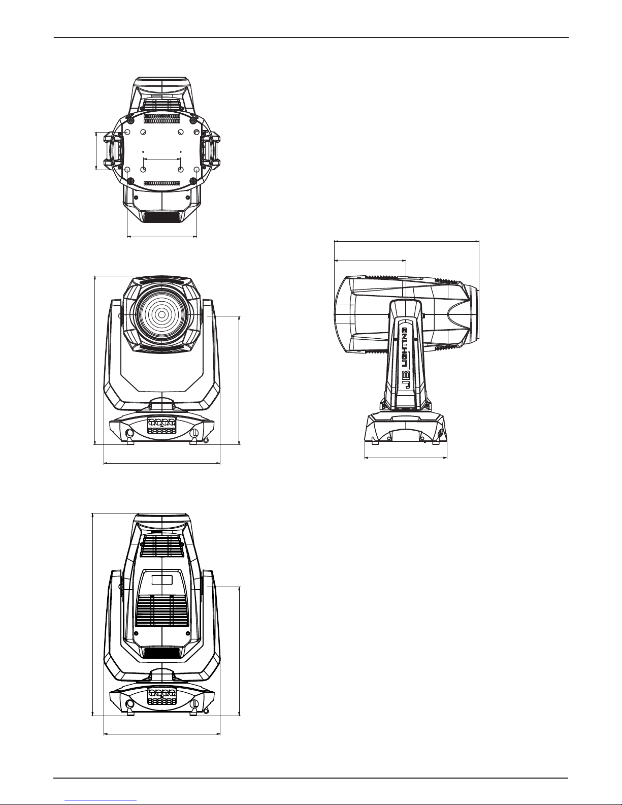
1. Dimensions
Name
Erstellt
Datum
Prisma
Fax.: 07304 / 9617-99
Tel.: 07304 / 9617-0
P18
17.01.2018
Kuehngruen
Allgemeintoleranzen
Blechdicke:
Material:
Farbe:
Oberfläche:
Abmessung:
Lichtanlagentechnik GmbH
Sallersteig 15, 89134 Blaus tein
6
3
0
435
4
8
0
,
5
1
4
0
140
258,4
307
267
541
Name
Erstellt
Datum
F
ax.: 07304 / 9617-99
Tel.: 07304 / 9617-0
17.01.2018
Kuehngruen
Blechdicke:
Material:
Farbe:
Oberfläche:
Abmessung:
Lich
tanlagentechnik GmbH
Sall
ersteig 15, 89134 Blaus tein
307
267
541
Name
Erstellt
Datum
Prisma
Fax.: 07304 / 9617-99
Tel.: 07304 / 9617-0
P18
17.01.2018
Kuehngruen
Allgemeintoleranzen
Blechdicke:
Material:
Farbe:
Oberfläche:
Abmessung:
Lichtanlagentechnik GmbH
Sallersteig 15, 89134 Blaustein
435
4
8
0
,
5
1
4
0
140
258,4
307
6
7
5
4
1
4
0
140
258,4
267
541
Page 5
- 05 -
P 18 W a s h
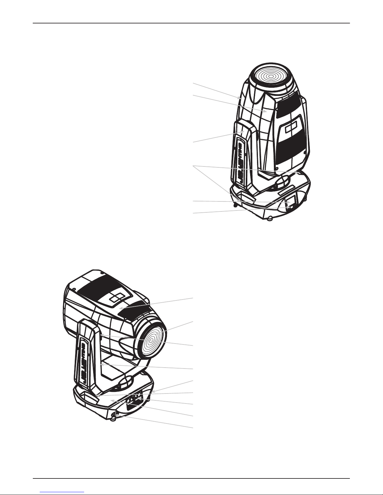
2. Product overview
Head
Fresnel front lens
Tilt lock
Arm
PowerCON TRUE1 Output
Pan lock
DMX/Ethernet/USB ports
Base
PowerCON TRUE1 Input
Bottom cover
Top cover
Arm cover
Handles
LCD display
Function keys
Page 6
- 06 -
P 18 W a s h
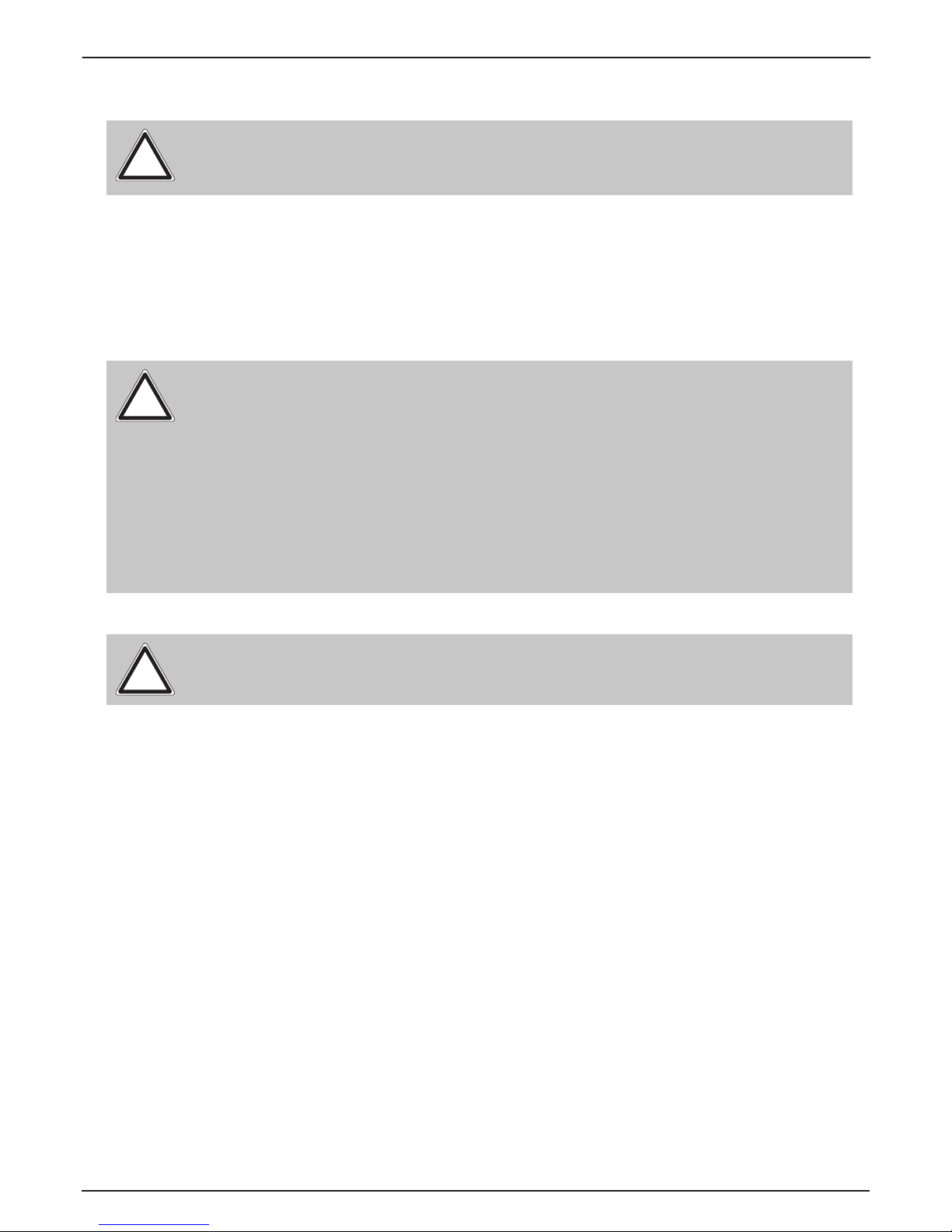
3. Introduction
ATTENTION: For your own safety, please read these operating instructions carefully
before rst use.
!
3.1 Safety instructions
This spotlight has left our company in excellent condition. To maintain this condition and to
ensure safe operation, it is absolutely essential to observe the following safety instructions and
warnings which are described in this operating manual.
The manufacturer accepts no liability for damage caused to the device by disregard of these
operating instructions or unauthorised modications.
Please note that damage caused by manual modications to this unit is not covered bythewarranty.
Ensure that the mains voltage to be connected is not higher than that indicated on the type plate.
Thisdevice should only be operated with the power source indicated on the type plate. If you are
not sure what type of power supply you have, contact your dealer or power supplier.
Always disconnect the device from the power supply before carrying out cleaning work or before
replacing fuses or parts.
The mains plug must always be accessible after the spotlight has been installed. Do not overload
the sockets or extension cables as this could result in re or electric shock. Do not place any
objects on the power cable. Do not install the spotlight in such a way that people can trip over
or step on the power cable. Make sure that the power cable can never be crushed or damaged
by sharp edges. Check the unit and the power cable from time to time.
Leave maintenance work to a qualied technician!
ATTENTION: This device is only suitable for professional use! Protection class IP 20
- only for use in dry environments (indoors)!
ATTENTION: JB-Lighting Lichtanlagentechnik GmbH does not authorise the use
of its devices in life support systems. Life-supporting systems are systems whose
purpose is to maintain or stabilise life and whose defect or malfunction may result
indeath or injury to persons.
The product in this manual complies with the following EU directives:
- Low Voltage Directive 2014/35/EU
- EMC Directive 2014/30/EU
ATTENTION: Disconnect the device from the power supply before opening thedevice.
You can suffer an electrical shock from touching live parts (high voltage).
!
!
Page 7
- 07 -
P 18 W a s h
Never connect this device to a dimmer pack.
During rst use, some smoke and odour may occur. This is normal and does not necessarily
mean that the device is defective.
The device becomes hot during operation. Never touch the device with bare hands during
operation!
When replacing fuses, only use the same types with identical values! Only have fuse replacement
carried out by a qualied technician
If the device has been exposed to strong temperature uctuations (e.g. after transport), thedevice
must not be switched on immediately. The resulting condensation can damage your device.
Leave the device switched off until it has reached room temperature.
Do not shake or knock the device. Avoid brute force during installation or operation.
This light was designed for indoor use only. Do not expose this device to rain or moisture.
When choosing a mounting location, make sure that the device is not exposed to extreme heat,
moisture or dust.
Ventilation openings and slots in the head and foot of the spotlight are used for ventilation
toensure reliable operation of the device and to protect it from overheating, these openings must
not be covered.
Never cover the front lens when the spotlight is in use.
The openings should never be covered with substances or other objects so that the airways are
blocked.
This device must not be operated in an environment without adequate ventilation.
The device may only be operated when the housing is closed and all screws/Camlocs are rmly
tightened.
The device must always be secured with an additional safety device.
Ensure that the area below the spotlight is clear during installation, alteration and removal.
ATTENTION: This xture corresponds to protection class I. For this reason, this
spotlight must be connected to a mains socket with earthing contact.
!
ATTENTION: DAMAGE TO EYES! Do not look into the light source for long periods
during operation. This can be harmful to the eyes. Attention: potentially hazardous
radiation - Risk group 2 per DIN EN 62471
Page 8
- 08 -
P 18 W a s h
4. Installation
3.2 Unpacking the device
Contents of the packaging: This spotlight, two Omega brackets with original Camloc fasteners,
powerCON-TRUE1 cable and a safety note. These instructions are included in the shipment.
Open the packaging at the top and remove the powerCON TRUE1 cable, the inlay and the safety
instructions. The Omega brackets are located under the spotlight. Check the P18 Wash for
possible transport damage. This should be communicated immediately to the transport company.
The maximum ambient temperature of 45°C must not be exceeded.
Do not operate the device until you have become familiar with its functions. Prevent operation by
persons who are not qualied to use the device. Most damage is the result of improper operation!
Please use the original packaging or specially adapted ight cases if the device is to betransported.
When using the original packaging, the locks must not be closed!
ATTENTION: Only have plugs installed by a specialist!
!
The P18 Wash spotlight is supplied with a partially assembled power cable with the powerCONTRUE1 plug (only the powerCON-TRUE1 plug is included in the US version). The installation of
thesafety plug or the connection of the P18 Wash to the power supply (100-240 Volt, 50 - 60
Hertz) must becarried out by an authorised specialist.
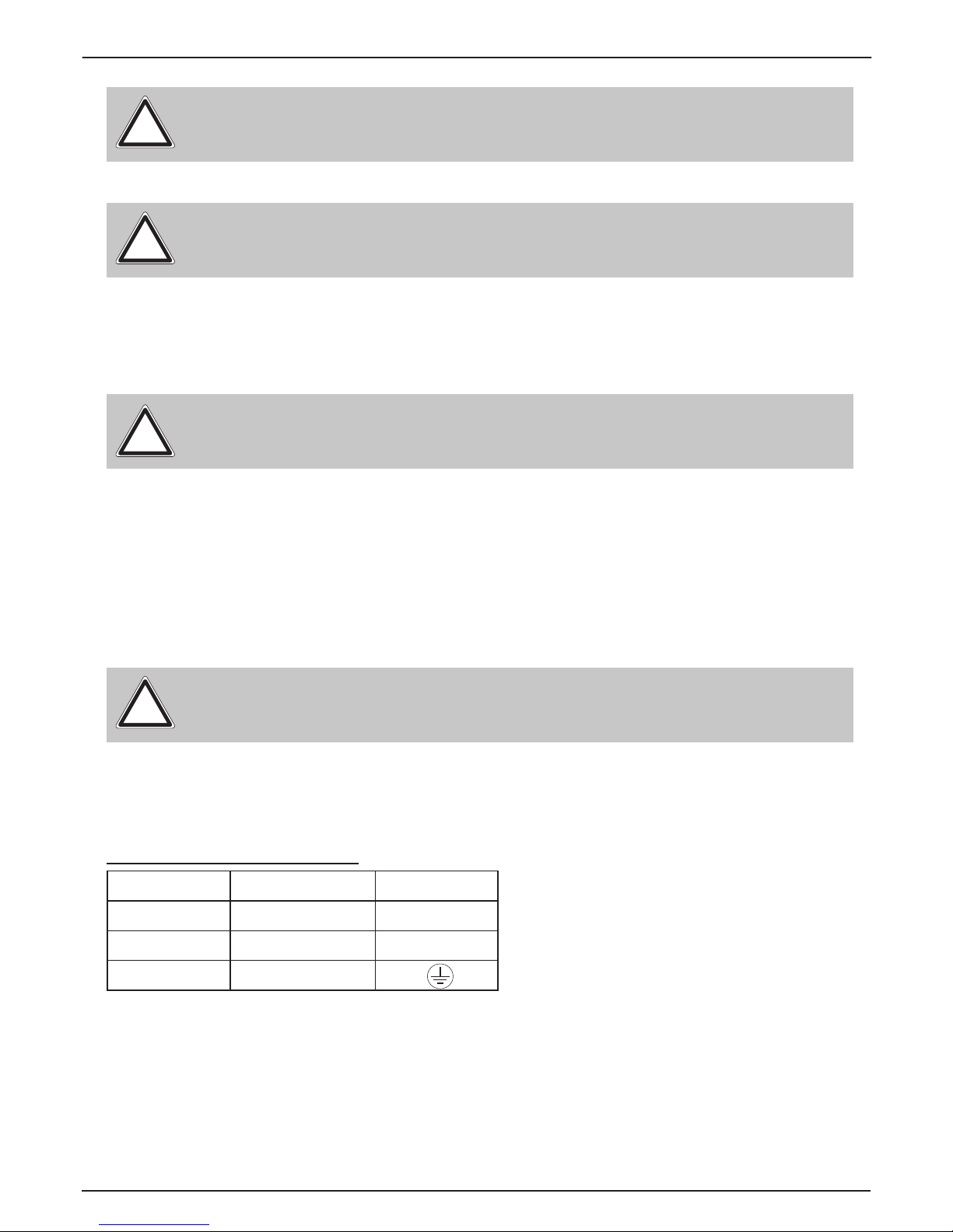
Connection in Germany/Europe:
Wire colour
Function
Symbol
Brown
Phase
“L”
Blue
Neutral wire
“N”
Green/Yellow
Protective earth
“PE”
4.1 Fitting the plug to the connection cable
ATTENTION: The distance between the light emission and the surface to be
illuminated must be at least 2.0 metres.
ATTENTION: The front lens must be replaced if it is visibly damaged to the extent
that itsfunction is impaired, e.g. by cracks or deep scratches!
ATTENTION: To avoid damaging the internal parts of the light head, never let sunlight
shine directly into the front lens.
!
!
!
Page 9
- 09 -
P 18 W a s h
Connected loads: Voltage 100-240 V, frequency 50 - 60 Hz, power max. 1200 VA
The electrical safety and function of the device can only be guaranteed if it is connected to a properly
installed protective conductor system. It is very important that this basic safety requirement
is met. If in doubt, have the electrical installation checked by a specialist. The manufacturer
cannot be held responsible for damage caused by a missing or interrupted protective conductor
(e.g. electric shock)! Only use the device when it is completely assembled so that no electrical
components can be touched. (Danger 100-240 V)
If you have observed the listed points, you can plug in the devices or have them connected
tothe mains by a specialist.
4.2 Mains connection
ATTENTION: The P18 Wash can light up immediately if standalone operation is activated oraDMX signal is present!
!
Connection outside Europe:
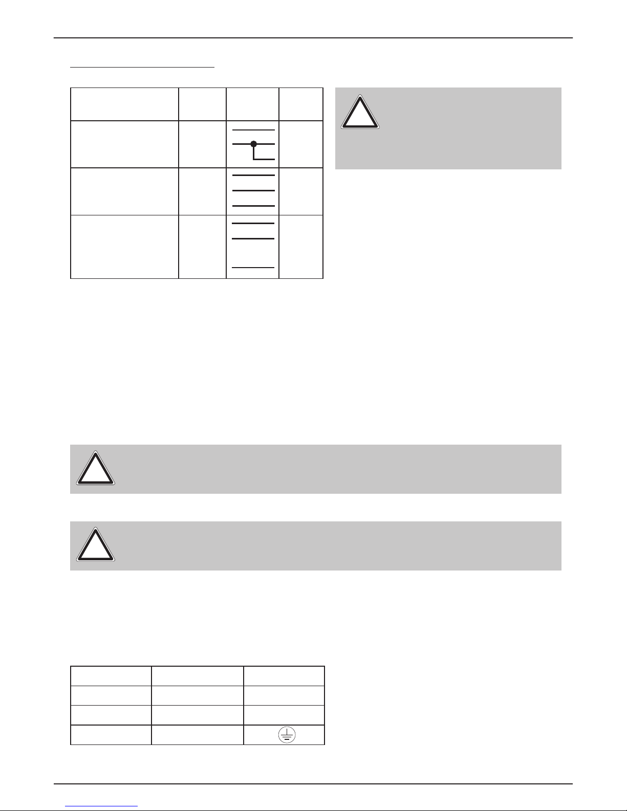
The P18 Wash may only be operated on the following power supply systems:
Mains
P18
Wash
2 wires, 1 phase L
N
L
N
PE
3 wires, 1 phase L
N
L
L
N
4 wires, 3 phases L
1
L
2
L
3
N
L
N
PE
ATTENTION:
In Canada, the P18 Wash may only
be operated in a 2-wire, 1 phase
network with a maximum voltage of
120V!
!
The P18 Wash has a powerCON-TRUE1 out power output. Depending on the local conditions
several devices can be linked by powerCON-TRUE1 in and powerCON-TRUE1 out. Connect a
maximum of two (when using 230V/16A) P18 Washs in a row.
Use an approved three-core cable with a cross-section of at least 1.5 mm². Cabling must be
done with the original Neutrik coded plugs. The installation instructions of the manufacturer
(www.neutrik.com) and the colour coding of the cable must be observed.
4.3 Wiring the power feed-through
ATTENTION: Only have it carried out by a specialist!
!
Wire colour
Function
Symbol
Brown
Phase
“L”
Blue
Neutral wire
“N”
Green/Yellow
Protective earth
“PE”
Page 10
- 10 -
P 18 W a s h
The P18 Wash has a DMX-in and DMX-out connector. Now connect the DMX output of your
controller to the 1st P18 Wash (Controller DMX-Out -> P18 Wash DMX-In). Then the 1st P18
Wash with the 2nd P18 Wash (P18 WashDMX-Out -> P18 Wash DMX-In) and so on. In some
cases it is advisable to insert a so-called end connector (XLR connector with a 120 Ohm
resistor between pin 2 and pin 3). Whether an end connector is required depends on various
factors, including the cable lengths used and the number of devices. However, as long as no
problems occur in the DMX line, this is not necessary.
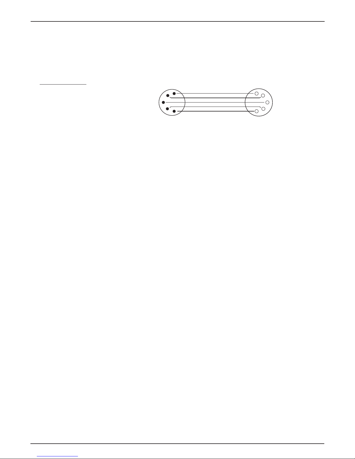
4.4 Signal connections
The DMX cabling (signal lines) should be done with a 4-pin cable with shielding. We recommend
a DMX cable (110 Ohm, 4x0.22mm
2
), alternatively a 2-pole micro cable can be used. The plugs
and sockets are 5-pin XLR connectors, which can be purchased in specialist shops.
Pin assignment:
Pin1 = Ground/Shielding
Pin2 = DMX Pin3 = DMX +
Pin4 = Data out Pin5 = Data out +
1
2
3
4
5
1
2
3
4
5
Cable with shielding
4.4.1 DMX cabling
4.4.2 Ethernet cabling
Ethernet cabling can be done with standard network lines. The sockets on the device are Neutrik
etherCON sockets. Special cables with etherCON connectors are recommended by Neutrik. The
two sockets on the P18 Wash are connected to each other via a switch. Up to 10 devices can
be connected in series without any delay. Of course, the spotlights can also be supplied in a star
conguration via an external switch.
4.4.3 Wireless reception
The P18 Wash is equipped as standard with a LumenRadio CRMX receiver for wireless DMX.
The receiver can process both DMX and RDM. If a cable and wireless connection are connected
to the P18 Wash, the cable connection has priority! The received signal can be output via DMX
and Ethernet as of software version 1.5 (see page 16).
Page 11

- 11 -
P 18 W a s h
4.5 Mounting the devices
WARNING: Allow a distance of at least 0.5 metres from easily ammable material.
!
The P18 Wash can be placed on the oor or hang on
a trussing system. Also a mounting horizontally to a
truss system like in the picture is allowed.
When placing the unit on the oor make sure that it
stands on rigid ground, because the air inlets in the
base must not be covered with anything!
140
258,4
140
Name
Erstellt
Datum
Prisma
Fax.: 07304 / 9617-99
Tel.: 07304 / 9617-0
06.11.2018
Kuehngruen
Allgemeintoleranzen
Blechdicke:
Material:
Farbe:
Oberfläche:
Abmessung:
Lichtanlagentechnik GmbH
Sallersteig 15, 89134 Blaustein
✔
✔
1 2 43
To mount the unit on a trussing system use two of the original JB-Lighting omega brackets with
original Camloc-connectors. You have following four possibilities to mount the omega brackets.
The Camlocs must snap in to be locked properly. Ensure that the structure (truss) to which you
are attaching the xture is secure. If you install the xture to a truss always attach a safety cable,
that can hold at least 10 times the weight of the xture.
✔
Page 12

- 12 -
P 18 W a s h
5. Control panel
The P18 Wash has a graphic colour touch display that can be rotated 180° when installed in a
suspended position. The display can be rotated via the touch screen from software version 1.5.
All parameters of the P18 Wash can be set on the control panel (see menu overview page 14).
Function and operation of the display
The main menu provides information regarding the set DMX mode and, when the wireless mode
is switched on, the eld strength of the associated transmitter module. "ENTER" calls up a submenu or conrms an input. "ESC" is used to exit a function or a menu item. "UP" and "DOWN"
are used to navigate within the menu and to enter values.
Special areas can only be called up using a specic key combination. To do this, press and hold
the "ENTER" key and then use the opposite "ESC" key to access the menu. To exit the function,
proceed in reverse order.
This applies in the SERVICE area for the FINE ADJUST function and in the STANDALONE area
for the MODIFY, RUN and REMOTE functions.
The main menu can also be locked to prevent unintentional access. It is also locked by pressing
the "ENTER" key (keep it pressed) and then additionally locking it with the opposite "ESC" key.
From software 1.5 onwards, all functions can also be operated via the touch display. Starting
with software 1.5, the display is enhanced to show the cooling mode and the set camera mode.
Page 13

- 13 -
P 18 W a s h
Display illumination as function display
The display illumination remains switched off during the reset. Slowly ashing display illumination
when "JB-Lighting" is displayed means no DMX signal is present.
A very rapidly ashing display illumination when "JB-Lighting" is displayed means that a new
error has been stored in the "ERROR LIST", also an error message in the display (e.g. *PAN
TIMEOUT) indicates this current error. This error occurs during this reset or in the operation
before. This error is now automatically set to "read", but remains in the "ERROR LIST".
A rapidly ashing display illumination shows an error in the "ERROR LIST" is still in it but has
already been conrmed or was automatically conrmed. Only when the error has been deleted
from the ERROR LIST does the P18 Wash start again without error signalling.
If errors occur again and again contact the dealer / distributor or our service department.
If the P18 Wash receives a DMX signal, the display illumination goes out after 30 seconds.
DMX addressing
In the main menu, the DMX address can be set directly by pressing the up/down keys.
Display operation via battery backup
By pressing the left button below the display, the conguration battery operation of the headlamp
is activated, so the headlamp can be congured without power. It is possible to congure all the
settings displayed by the menu, for example the DMX address can be set.
Page 14

- 14 -
P 18 W a s h
5.1 Menu overview
CURVES DIMMER CURVE SQUARE
FACTORY DEF. LOAD DEFAULTS SURE?
DMX / NET ADDR ADDRESS +/-
ENTER
ENTER ENTER
PERSONALITY
DMX INPUT CONFIG ON/OFF
UNLINK
NETWORK
PAN / TILT RESOLUTION
PAN INVERS
TILT INVERS
PAN/TILT SWAP
16 BIT
8 BIT
NORMAL
INVERS
NORMAL
INVERS
NORMAL
INVERS
WLJB DMX HOLD
FADE OUT
DMX HOLD
SERVICE
RESET FIXTURE
SURE?
ERROR LIST
LIST
CLEAR
FUNCTION TEST
START TEST
INIT PAN/TILT
TEST RUNNING
SURE?
PAN TIMEOUT COUNT: 1 CLEAR?
SURE?
DMX TEST
DMX CHANNEL CH 001: --- +/-
DISPLAY CONTR.
D. CONTR: +000 +/-
UP
USER DEFAULTS
LOAD DEFAULTS SURE?
SAVE DEFAULTS SURE? PASSWORD
COOLING MODE
STANDARD
BOOST
SHORTEST DIST. ON
OFF
CAMERA MODE
60 HZ
FLEX
50 HZ
LINEAR
LONGLIFE
FINE ADJUST
OFS FOCUS
RECEIVE SOFTW.
SURE?
THEATRE WHISPER
THEATRE SILENT
FAST
DMX ADDRESS
ADDRESS +/-ARTNET ADDRESS
DMX MODE MODE 1
MODE 2
ON
OFF
DEFAULT IP NETWORK 10
NETWORK 2
USER IP BYTE 1
BYTE 2
BYTE 3
BYTE 4
ADDRESS +/-
ADDRESS +/-
ADDRESS +/-
ADDRESS +/-
SURE?
WIRELESS
ARTNET
OFS BL1A
OFS BL1B
OFS BL2A
OFS BL2B
OFS BL3A
OFS BL3B
OFS BL4A
OFS BL4B
OFS BL1A +/-
OFS BL1B +/-
OFS BL2A +/-
OFS BL2B +/-
OFS BL3A +/-
OFS BL3B +/-
OFS BL4A +/-
OFS BL4B +/-
OFS FOCUS +/-
Page 15

- 15 -
P 18 W a s h
STANDALONE
EDIT STEP NR. +/-
RUN
TIMEBASE 1 SEC
1/10 SEC
MODIFY
REMOTE
CAPT DMX
INSERT
DELETE
RESET STEP
CLEAR ALL
INFO
SOFTWARE VER.
FIRMWARE VER.
TOT OP. TIME
TEMP BASE LCD ACTUAL
MAX RESET?
TEMP HEAD MAIN ACTUAL
MAX RESET?
FADE TIME FADE TIME +/-
NEXT TIME NEXT TIME +/-
PAN PAN +/-
TILT TILT +/-
CONTROL CONTROL +/-
SHUTTER SHUTTER +/-
DIMMER DIMMER +/-
FOCUS FOCUS +/-
ZOOM ZOOM +/-
IRIS IRIS +/-
BL 1A
BL 1B
BL 2A
BL 2B
BL 3A
BL 3B
BL 4A
BL 4B
BL 1A +/-
BL 1B +/-
BL 2A +/-
BL 2B +/-
BL 3A +/-
BL 3B +/-
BL 4A +/-
BL 4B +/-
COLOR 1
CYAN
MAGENTA
BL ROT BL ROT +/-
COLOR 1 +/-
CYAN EFF +/-
MAGENTA +/-
TEMP HEAD DRV ACTUAL
MAX RESET?
YELLOW
CTO
SPARKLE
SPARKLE SP
FROST
FROST 2
SPEED P/T
SPEED EFF
MOVE B-OUT
YELLOW +/-
CTO +/-
SPARKLE +/-
SPARKLE SP +/-
FROST +/-
FROST 2 +/-
SPEED P/T +/-
SPEED EFF +/-
MOVE B-OUT +/-
TEMP BASE PS ACTUAL
MAX RESET?
TEMP HEAD LED ACTUAL
MAX RESET?
TEMP HEAD AMB. ACTUAL
MAX RESET?
TOT BAT CHARGE T.
COLOR 2 COLOR 2 +/-
FOCUS DISTANCE FOCUS DIST. +/-
FOCUS ADJUST FOCUS ADJ. +/-
Page 16

- 16 -
P 18 W a s h
5.2 FACTORY DEFAULTS - Factory settings
To reset P18 Wash to the factory settings, go to the menu item FACTORY DEFAULTS, LOAD
DEFAULTS. After conrming the security prompt SURE? with “ENTER”, all parameters are reset
to the factory settings.
5.3 USER DEFAULTS - User settings
If the user has set the P18 Wash in the PERSONALITY menu to their personal settings, these can
besaved and loaded in the USER DEFAULTS menu. In order to prevent unintentional alteration
of the data, you must enter the following password during the saving process: “JB-LIGHTING”.
5.4 DMX / NET ADDRESS - DMX addressing / Artnet addressing
The DMX addressing can be done either directly in the display. Press the "UP" or "DOWN"
button to set the desired DMX address. The value is conrmed with the "ENTER" key. However,
the DMX addressing can also be done within the menu item DMX / NET ADDR, and there under
DMX ADDRESS.
To set the Artnet address, the menu item ARTNET ADDRESS must be selected in the DMX
/ NET ADDR menu. The Artnet address can now be set using the UP / DOWN buttons. The
Artnet address is displayed in the form 000.00.00. This display corresponds to: Netz.Subnetz.
Universum.
5.5 PERSONALITY - Personal settings
DMX INPUT MODE
In this menu item the options WIRELESS and NETWORK are available.
Under WIRELESS -> ON / OFF the factory-installed radio DMX receiver module of Lumen-Radio
can be activated or deactivated and via WIRELESS -> UNLINK the connection to the connected
transmitter can be deleted. In order to connect the xture to a transmitter, wireless must be
set to ON on the xture and the connection button must be pressed briey on the transmitter.
The transmitter is now looking for all xtures where wireless is enabled and xtures that are not
connected to a transmitter. If the P18 Wash has successfully connected to the transmitter, the
display shows a level indication of the current reception quality. If the P18 Wash is additionally
connected via the DMX / etherCON connection sockets, these signals have priority over the
radio link. Using the key shortcut ESC and DOWN, pressed in the main menu, the headlamp can
be booked out of the booked transmitter (see page 19).
Under NETWORK -> ARTNET, the IP address of the xture must be selected or set for Artnet
operation. Each xture has a unique standard IP address. Under ARTNET -> DEFAULT-IP this
can only be changed from the network 10.xxx.xxx.xxx to a network 2.xxx.xxx.xxx. You can set
your own customer-specic IP address under ARTNET -> USER-IP. This address is divided into
BYTE1 to BYTE 4 and can be set one after the other.
DMX MODE
The P18 Wash has 2 operating modes (see channel assignment page 20). All parameters of
P18 Wash can be operated via mode 1. However, all channels (except pan/tilt) are controlled with
8 bits. Byselecting Mode 2 - 16 Bit the gobo, prism rotation, CMY/CTO, dimmer, focus, zoom,
thecomplete shutter slide unit as well as pan/tilt are controlled via 16 Bit.
PAN/TILT
The motion resolution can be changed from 16 bits to 8 bits under RESOLUTION. In the factory
setting, this is set to 16 bits. In 8-bit resolution, the P18 Wash can be positioned less precisely,
but can be operated more rapidly depending on the lighting console. The menu items PAN
INVERSE and TILT INVERSE allow you to invert the direction of movement. Under PAN/TILT
SWAP, the “Pan” and “Tilt” channels can be interchanged.
Page 17

- 17 -
P 18 W a s h
CAMERA MODE
To avoid ickering during TV recordings, the P18 Wash can be adjusted from 50 Hertz (PAL,
Secam) to 60 Hertz (NTSC) for different camera systems. Flex mode is set when using different
camera systems or when shooting with mobile phone cameras or similar non-professional
cameras. A HighFlex mode is also available. In this mode, the repetition frequencies are set
to 3 kHz, which is necessary to ensure smooth movements in dimmed lighting scenes. The
factory setting oftheP18 Wash is 60 Hertz. The changeover is also possible with the light mixing
console via thecontrol channel.
COOLING MODE
In the COOLING MODE menu item you can set the fan control, the speed of the effects and
thebrightness of the P18 Wash. The following settings are available.
THEATRE WHISPER: Brightness 27000lm, all effect/pan/tilt speeds are minimal and therefore
run very quietly (volume 29dB(a)). In this mode, the spotlight runs at the same brightness up to
an ambient temperature of 60°C. It is not necessary to run the fans in this mode.
THEATRE SILENT: Brightness 29000lm, all effect/pan/tilt speeds are somewhat minimised compared to the standard mode, from 40°C ambient temperature the spotlight regulates theLED
power slightly downwards and thus remains at the same volume up to 60°C.
STANDARD: Brightness 32000lm, all effect/pan/tilt speeds run at full speed. From an ambient
temperature of approx. 36°C the fans run to cool the LED accordingly. The brightness remains
constant up to 60° ambient temperature.
BOOST: Brightness 34000lm, all effect/pan/tilt speeds run at full speed. The fans run a little
stronger in this mode, from approx. 40° ambient temperature the fans run again accordingly.
LONGLIFE: Brightness 32000lm, all effect/pan/tilt speeds run at full speed. The fans run a little
stronger in this mode, from approx. 40° ambient temperature the fans run again accordingly. We
would recommend this mode for permanent installations, as the LED module runs cooler and
thus more “stress-free”.
There is no danger to the life of the device in any mode, as the P18 Wash has a temperature safety shutdown. In addition, the LED module is switched off from an ambient temperature of 60°C!
CURVES
The dimmer curve can be changed from exponential (square) to linear. The “exponential” dimmer
curve (factory setting) causes the dimmer to fade in and out more smoothly.
SHORTEST DISTANCE
This menu item addresses both the colour wheel channel and the gobo wheel channels. Inthe
factory setting (ON), the colours/gobos change with each other over the shortest distance.
Switching to OFF causes the colour/gobo to change only in the order specied by the wheels.
Page 18

- 18 -
P 18 W a s h
5.6 STANDALONE operation
In standalone operation, up to 20 program steps can be stored in the P18 Wash, which can then
run in an endless loop. The images can be saved in two ways. Either you program the desired
DMX values directly on P18 Wash and save them, or you set the DMX values via a connected
DMX console and then store them in the P18 Wash.
The menu items MODIFY, RUN and REMOTE can only be called up using a specic key
combination. To do this, press and hold “ENTER”, and also press “ESC”. Before activating these
menu items, remove all other devices in the DMX line that send DMX, e.g. consoles or other
spotlights that are not congured as slave devices, as otherwise damage to the DMX drivers
may occur.
Programming the standalone programme on the spotlight display:
Call up the STANDALONE, EDIT menu item. In the STEP NR+/- menu item, select the desired step
and you can change it and its channel parameters in the following menu items: In theMODIFY
menu item, set the desired lighting scene and position and determine the individual sequence
times of the steps with FADE TIME and NEXT TIME (time for the complete step).
Use INSERT to insert an additional programming step. The DMX values of the previous step are
copied to the new step.
Use DELETE to delete a step. The display shows STEP NR: 1/X. Use the selection keys to move
to the desired step.
With RESET STEP you reset one step to its default values (DMX 000). The display shows STEP
NR: 1/X. Use the selection keys to select your step. CLEAR ALL resets the complete standalone
programming steps. Under MODIFY you will nd STEP1/1 again. In the STANDALONE, TIMEBASE
menu item you have the possibility to change the Fade Time and Next Time from 1 second to
1/10 second.
Launch the standalone program:
Call up the STANDALONE menu and navigate to the RUN submenu. Conrm the selection by
pressing the key combination “ENTER” (press and hold) and simultaneously “ESC”. The display
then shows: S-ALONE: 01/XX and the program runs in an endless loop.
Deactivation: Press and hold the “ESC” key and then also press "ENTER". The menu jumps back
one level and RUN appears in the display.
Operation via master-slave function:
Connect the P18 Wash via DMX lines and activate the REMOTE menu item for all slave devices.
Todothis, navigate in the STANDALONE menu to the REMOTE sub-menu. Activate the REMOTE
function by pressing and holding “ENTER”, and also pressing “ESC”. The spotlight is in slave
mode when the display shows the status REMOTE INACTIVE or REMOTE ACTIVE.
REMOTE INACTIVE: The P18 Wash is in slave mode but does not receive a DMX signal.
REMOTE ACTIVE: The P18 Wash is in slave mode and receives a DMX signal.
The master device is programmed via the MODIFY menu item and started via RUN (press
andhold “ENTER” and also press “ESC”).
Accept the DMX values from an external console:
To accept the DMX values of a connected console, you must rst enable the Capture DMX input.
To do this, go to the CAPT DMX menu item. The display now shows CAPTURE DMX 01/01, press
the Enter key to switch to START CAPTURE. Now the P18 Wash reacts to the signals from the
external console.
From Spotlight Software 1.5 the standalone operation can also be programmed via theApp
we offer.
Page 19

- 19 -
P 18 W a s h
5.7 INFO
The Info menu informs you about the respective software and rmware status, about the total
operating time and the different temperatures of the spotlight. The rst two menu items in theInfo
area are the software version and the rmware version, whereby the software version is an
important source of information for our service requests, the rmware version is less important
source of internal information. Under the menu item TOT OPERATE TIME the total operating time
of the spotlight is displayed. This cannot be deleted!
The following temperatures are also displayed:
TEMP BASE LCD, the temperature on the display board
TEMP BASE PS, the temperature of the power supply unit
TEMP HEAD MAIN, the temperature of the head board
TEMP HEAD DRV, the temperature of the LED driver board
TEMP HEAD LED, the temperature of the LED module
TEMP HEAD AMBIENT, the temperature in the head next to the air inlet (ambient temperature)
Both the current temperature and the maximum temperature are displayed. The maximum
temperatures can be individually deleted.
5.8 Shortcuts - quick access
Pressing the ESC and DOWN buttons in the main menu will log the xture off the programmed
Lumen Radio Wireless transmitter. The xture is now ready to be logged in another transmitter.
Page 20

- 20 -
P 18 W a s h
6. Channel assignment
The P18 Wash has 2 different DMX modes. The respective mode can be set in the PERSONALITYDMX MODE menu item. The set mode is displayed in the main menu.
6.1 Operating modes
Mode 1(M1) Mode 2 (M2)
Channel 1 Pan Pan
Channel 2 Pan ne Pan ne
Channel 3 Tilt Tilt
Channel 4 Tilt ne Tilt ne
Channel 5 Control channel Control channel
Channel 6 Shutter Shutter
Channel 7 Dimmer Dimmer
Channel 8 Focus Fine dimmer
Channel 9 Zoom Focus
Channel 10 Focus distance Fine focus
Channel 11 Focus adjust Zoom
Channel 12 Iris Fine zoom
Channel 13 Aperture 1a Focus distance
Channel 14 Aperture 1b Focus adjust
Channel 15 Aperture 2a Iris
Channel 16 Aperture 2b Fine iris
Channel 17 Aperture 3a Aperture 1a
Channel 18 Aperture 3b Aperture 1a ne
Channel 19 Aperture 4a Aperture 1b
Channel 20 Aperture 4b Aperture 1b ne
Channel 21 Aperture rotation Aperture 2a
Channel 22 Colour wheel 1 Aperture 2a ne
Channel 23 Colour wheel 2 Aperture 2b
Channel 24 Cyan Aperture 2b ne
Channel 25 Magenta Aperture 3a
Channel 26 Yellow Aperture 3a ne
Channel 27 CTO Aperture 3b
Channel 28 Sparkle Aperture 3b ne
Channel 29 Sparkle speed Aperture 4a
Channel 30 Frost 1 Aperture 4a ne
Channel 31 Frost 2 Aperture 4b
Channel 32 Pan/tilt speed Aperture 4b ne
Channel 33 Effect speed Aperture rotation
Channel 34 Blackout Move Fine aperture rotation
Channel 35 Colour wheel
Channel 36 Colour wheel
Channel 37 Cyan
Channel 38 Fine cyan
Channel 39 Magenta
Channel 40 Fine magenta
Channel 41 Yellow
Channel 42 Fine yellow
Channel 43 CTO
Page 21

- 21 -
P 18 W a s h
Channel 44 CTO ne
Channel 45 Sparkle
Channel 46 Sparkle speed
Channel 47 Frost 1
Channel 48 Frost 2
Channel 49 Pan/tilt speed
Channel 50 Effect speed
Channel 51 Blackout Move
Page 22

- 22 -
P 18 W a s h
6.2 DMX channel assignment Mode 1 and Mode 2
M1 M2 Function DMX
1 1 Pan (X) movement 561° 000-255
2 2 Pan (X) ne (16 Bit) 000-255
3 3 Tilt (Y) movement 281.0° 000-255
4 4 Tilt (Y) ne (16 Bit) 000-255
5 5 Control channel
Dimmer fade out via fader - rapid -> slow (rapid mixer response time)
Dimmer fade out via fader - rapid -> slow
Dimmer fade out via fader - rapid -> slow
Dimmer fade out via fader - rapid -> slow
Dimmer fade out via fader - rapid -> slow (rapid mixer response time)
THEATRE WHISPER cooling mode (dimmer/shutter closed, then after 2 sec.)
THEATRE SILENT cooling mode (dimmer/shutter closed, then after 2 sec.)
STANDARD cooling mode (dimmer/shutter closed, then after 2 sec.)
BOOST cooling mode (dimmer/shutter closed, then after 2 sec.)
LONGLIFE cooling mode (dimmer/shutter closed, then after 2 sec.)
Camera Mode, 50Hz (after 2 sec.)
Camera Mode, 60Hz (after 2 sec.)
Camera Mode, FLEX (after 2 sec.)
Camera Mode, High FLEX (after 2 sec.)
Safety
Reset (after 2 sec.)
Safety
000-007
032-039
064-071
096-103
128-135
160-160
161-161
162-162
163-163
164-164
208-215
216-223
224-227
228-231
232-239
240-247
248-255
6 6 Shutter
Shutter closed
Shutter open
Open pulsing shutter >20Hz (rapid - slow)
Shutter open
Fade effect with dimmer (slow - rapid)
Shutter open
Shutter closed
Open pulsing shutter <20Hz (rapid - slow)
Shutter open
Close pulsing shutter >20Hz (rapid - slow)
Shutter closed
Shutter fade, 0% (rapid - slow)
Shutter open
Shutter fade, 100% (rapid - slow)
Shutter closed
Random shutter 100% (rapid - slow)
Shutter open
Random shutter 0% (rapid - slow)
Shutter closed
Random shutter fade, 0% (rapid- slow)
Shutter open
Random shutter fade, 100% (rapid- slow)
Shutter open
000-015
016-095
096-110
111-111
112-125
126-126
127-126
128-142
143-143
144-158
159-159
160-174
175-175
176-190
191-191
192-206
207-207
208-222
223-223
224-238
239-239
240-254
255-255
7 7 Dimmer 0 - 100% 000-255
8 Fine dimmer (16Bit) 000-255
Page 23

- 23 -
P 18 W a s h
8 9 Focus 0-100% 000-255
10 Fine focus (16 Bit) 000-255
9 11 Zoom 0 -100% (near 13° - far 65°) 000-255
12 Fine zoom (16 Bit) 000-255
10 13 Auto focus distance
Auto focus off
Auto focus 0 m - 100 m
000-001
002-255
11 14 Auto focus adjust
Auto focus adjust - DMX 128 center 000-255
12 15 Iris 0-100% (open -> closed) 000-255
16 Fine iris (16Bit) 000-255
13 17 Aperture 1a 0-100% 000-255
18 Aperture 1a fine (16 Bit) 000-255
14 19 Aperture 1b 0-100% 000-255
20 Aperture 1b fine (16 Bit) 000-255
15 21 Aperture 2a 0-100% 000-255
22 Aperture 2a fine (16 Bit) 000-255
16 23 Aperture 2b 0-100% 000-255
24 Aperture 2b fine (16 Bit) 000-255
17 25 Aperture 3a 0-100% 000-255
26 Aperture 3a fine (16 Bit) 000-255
18 27 Aperture 3b 0-100% 000-255
28 Aperture 3b fine (16 Bit) 000-255
19 29 Aperture 4a 0-100% 000-255
30 Aperture 4a fine (16 Bit) 000-255
20 31 Aperture 4b 0-100% 000-255
32 Aperture 4b fine (16 Bit) 000-255
21 33 Aperture slider rotation -45° / +45° 000-255
34 Fine aperture slider rotation (16 Bit) 000-255
Page 24

- 24 -
P 18 W a s h
22 35 Colour wheel 1
White
White/Red
Red
Red/Yellow
Yellow
Yellow/Magenta
Magenta
Magenta/Green
Green
Green/Orange
Orange
Orange/Dark Blue
Dark Blue
Dark Blue/HCRI
HCRI
HCRI/White
Linear colours: White - Red - Yellow - Magenta - Green - Orange Dark Blue - HCRI - White
Colour cycle, right (rapid - slow)
Colour cycle, left (slow - rapid)
000-001
002-003
004-005
006-007
008-009
010-011
012-013
014-015
016-017
018-019
020-021
022-023
024-025
026-027
028-029
030-031
064-191
192-223
224-255
23 36 Color wheel 2
Open
2700K
3200K
4200K
7000K
9000K
12000K
Dark blue
000-001
002-003
004-005
006-007
008-009
010-011
012-013
014-255
24 37 Cyan (8 Bit) 0-100% 000-255
38 Fine cyan (16 Bit) 000-255
25 39 Magenta (8 Bit) 0-100% 000-255
40 Fine magenta (16 Bit) 000-255
26 41 Yellow (8 Bit) 0-100% 000-255
42 Fine yellow (16 Bit) 000-255
27 43 CTO (8 Bit) 0-100% 000-255
44 Fine CTO (16 Bit) 000-255
28 45 Sparkle - Glitter effect
Sparkle effect inactive
Sparkle effect intensity (minimum - maximum)
000-000
001-255
29 46 Sparkle speed
Faded sparkle effect (slow -> rapid)
Switched sparkle effect (slow -> rapid)
Repetition of the fading and switching blocks
000-031
032-063
064-255
Page 25

- 25 -
P 18 W a s h
30 47 Frost 1
Frost 0-100% 000-255
31 48 Frost 2
Frost 0-100% 000-255
32 49 Pan/tilt speed
Real-time motion
Delayed motion (rapid - slow)
000-003
004-255
33 50 Effects speed
Real-time effects
Delayed effects (rapid - slow)
000-003
004-255
34 51 Blackout Move
Not assigned
Blackout during pan/tilt
Blackout during Colour, CMY, Iris, Frost
Blackout during Colour, CMY, Iris, Frost, Zoom, Focus
Blackout during Colour, CMY, Iris, Frost, Pan/Tilt
Blackout during Colour, CMY, Iris, Frost, Zoom, Focus, Pan/Tilt
000-095
096-127
128-159
160-191
192-223
224-255
Various spotlight functions can be permanently switched via the control channel. The response
behaviour via DMX, the cooling and volume, the repetition frequency of the LED module can
beswitched and a spotlight reset can be triggered.
This channel can be used to adjust the response behaviour of the P18 Wash when dimming out
via faders to lighting controls from various manufacturers. Set DMX 000 for rapid dimming out
and DMX 007 for slow dimming out. This range is repeated ve times and thus the P18 Wash
is adapted to the reaction time/speed of the light controllers (DMX 000-007 for “rapid” light
controllers and DMX 128-135 for “slow” light controllers).
In the range from DMX 160 to DMX 164 the “Cooling” and “Volume” operating modes can be set.
To do this, the dimmer and shutter of the spotlight must be closed and the corresponding DMX
value must then be transmitted for 2 seconds.
DMX 160 (62.8%): THEATRE WHISPER cooling mode
DMX 161 (63.2%): THEATRE SILENT cooling mode
DMX 162 (63.6%): STANDARD cooling mode
DMX 163 (64.0%): BOOST cooling mode
DMX 164 (64.4%): LONGLIFE cooling mode
The repetition frequency (50/60/600Hz/3kHz) of the LED engine can also be set via this channel.
DMX 208-215 Camera Mode, 50Hz (after 2 sec.)
DMX 216-223 Camera Mode, 60Hz (after 2 sec.)
DMX 224-231 Camera Mode, FLEX 600Hz (after 2 sec.)
DMX 224-231 Camera Mode, FLEX 3000Hz (after 2 sec.)
A spotlight reset can also be triggered.
DMX 240-247 Reset (after 2 sec.).
After the Cooling Mode, Camera Mode and Reset commands, this channel must be reset to its
original value. See channel assignment on page 22.
6.3 Control channel
Page 26

- 26 -
P 18 W a s h
7. Service
7.1 Service menu
RESET FIXTURE
Upon the “Reset” command, P18 Wash will initialise to its initial values. It is the same procedure
asafter switching on the P18 Wash. If an error message appears in the display, this could be the
rst step to correct it.
ERROR LIST
The P18 Wash stores all occurring errors internally. An error message can have a harmless cause.
Ifyou experience frequent error messages, please contact your dealer or the JB-Lighting service
department. All error messages are displayed with the respective frequency and can be deleted.
FUNCTION TEST
This function allows you to test all functions of the P18 Wash without using a light mixer. The
pan/tilt reset is deactivated in the process.
DMX TEST
This menu item is used to test the DMX input. Use the function keys to select the DMX channel
to be tested. The display shows the incoming value, at the same time the P18 Wash reacts accordingly.
INIT PAN TILT
The P18 Wash is calibrated in the pan/tilt position at the factory. If it loses this calibration, i.e. it
strikes against the stop or no longer nds its position, it can be re-initialised using this function.
Thisprocess takes about 3-4 minutes and ends with a reset of the spotlight.
DISPLAY CONTRAST
The contrast of the LCD display may change when the temperature is too high. In this menu item
thecontrast can be adjusted.
RECEIVESOFT
This area can be used to import the software of the P18 Wash (see page 27).
Animation effects can be created via this channel in connection with the focus. Depending
ontheintensity, the projection can be made to shake more or less. This effect can be dimmed
or switched.
6.5 Sparkle effect, sparkle speed
FINE ADJUST
To access the “Fine Adjust” menu area, press and hold the “ENTER” key and then conrm
bypressing the “ESC” key opposite.
Focus:
The focus is calibrated at the factory to ensure that all spotlights are focused at the same distance
with the same zoom. If a spotlight loses this calibration or if parts have to be changed for repair,
the focus can be readjusted after repair. For further details please contact your dealer or JBLighting service department.
Apertures 1a, 1b, 2a, 2b, 3a, 3b, 4a, 4b:
The individual apertures are calibrated ex works to ensure that the opposite apertures of all delivered P18 Washs are just about closed at values of DMX 127.5. For further details please contact
your dealer or JB-Lighting service department.
Using the two channels autofocus distance and autofocus adjustment can be from Software Ver.
1.5 the focus over the entire zoom range automatically be readjusted.
6.4 Zoom, auto focus distance, autofocus adjust
Page 27

- 27 -
P 18 W a s h
7.4 Cleaning the device
You should check the function of the fans in thehead and
foot at regular intervals. Above all, make sure that the air
intakes and the interior ofthe P18 Wash are free of uff
and dust.
To do this, open the head cover (4x camlocks (4) with half
a turn) and the base plate on thefoot. You can clean the
P18 Wash with a brush and a vacuum cleaner. In addition,
you can remove the color insert (1) and the shutter slide
insert (2) by loosening the knurled screws (3) and sliding
the focus carriage towards the lens. Then you can clean
the colour lters and CMY panes with a soft cloth and a
little window cleaner. To clean the frost aps and zoom/
focus unit, remove the three Phillips screws (Fig. 4) and
then the cover (see Fig. 5). Ensure that you do not bend
or damage any parts during cleaning. When cleaning is
complete, reconnect the ap, replace the Phillips screws
(4) and return the inserts tothe unit.
(4) (5)
2
1
3
7.5 Software update
The P18 Wash can be updated via a USB stick with micro-USB connection. To do this, copy the
le directly into the root directory of the USB stick. Then press and hold the right key below the
display. Now insert the P18 Wash as soon as the message “Insert USB stick” appears on the
display and release the key. Now plug in the USB stick on the back of the device below the signal
connections and follow the instructions on the display. The P18 Wash completes the software
update with a reset. You will nd the latest software on our homepage.
7.6 Testing of electrical equipment
According to the German Social Accident Insurance (DGUV) Regulation 3 / Regulation 4, electrical
systems and equipment must be subjected to regular inspections. The xing screw of the DMX
5-pin socket can be used as measuring point for insulation and residual current measurement.
The screw is connected to all sheet metal parts via a contact washer.
PE measuring point
Page 28

- 28 -
P 18 W a s h
8. Specifications
Dimensions and weight
Length ................................................................307 mm
Width .................................................................435 mm
Height ................................................................754 mm
Net weight ...............................................................31 kg
Electronic system
Mains connection .......................................... 100-240 V AC, 50-60Hz
Maximum power consumption .............................................1200 VA
Power consumption in standby ..............................................200 VA
Temperature
Maximum ambient temperature ..............................................45 °C
Minimum ambient temperature ................................................5 °C
Optics, Photometric Data
Light source ......................................... White light LED module 1000W
Luminous intensity ...........................................34000 Lumen @ 20°C
Luminous intensity HCRI .......................................27000 Lumen @ 20°C
Effects
Pan ................................................................... 561.0°
Tilt .................................................................... 281.0°
Zoom ................................................................ 13° - 65°
Construction
Colour ..................................................................black
Housing ...............................................................PC ABS
Protection class ........................................................... IP 20
Plug-in technology ..........................................................yes
Installation
Installation site .......................................................... indoors
Holder .......................................................2x Omega brackets
Position ...................................................................any
Minimum distance to ammable objects .......................................0.5 m
Connections
Power input .............................................Neutrik powerCON TRUE1
Power feed-through ......................................Neutrik powerCON TRUE1
DMX/RDM in/out USITT DMX512 ....................................5-pin, in/out XLR
Ethernet in/out .................................................. Neutrik etherCON
Micro-USB ...................................................... Software update
Page 29

- 29 -
P 18 W a s h
9. Declaration of Conformity
Declaration of Conformity
in the sense of the Directive: 2014/35/EU Low Voltage Directive,
(Directive 2014/35/EU of the European Parliament and of the Council of 26/02/2014 to approximate
thelaws of the Member States relating to electrical equipment designed
for use within certain voltage limits)
in the sense of the Directive: 2014/30/EU Electromagnetic compatibility
(Directive 2014/30/EU of the European Parliament and of the Council of 26/02/2014 to approximate the
laws of the Member States relating to electromagnetic compatibility)
The manufacturer, JB-Lighting Lichtanlagentechnik GmbH
Sallersteigweg 15
89134 Blaustein-Wippingen
declares that the product: Varyscan P18 Wash
complies with the essential protection requirements of the directives. The following standards were used for conformity
assessment:
Emissions requirements Information technology equipment, radio interference characteristics per EN 55022:2010 Limit values and measuring methods - Limit value class A
Conducted interference emission requirements for information technology equipment, radio interference
EN 55022:2010 characteristics Limit values and measuring methods - Limit value class A
Radiation Information technology equipment, radio interference characteristics -
EN 55022:2010 Limit values and measuring methods - Limit value class A
Harmonic currents Electromagnetic compatibility
EN 61000-3-2:2015 Part 3-2: Limits, testing of harmonic currents
(for devices with an input current < 16A per phase)
Flicker Electromagnetic compatibility (EMC)
EN 61000-3-3:2013 Part 3-3: Limits, limitation of voltage changes,
Voltage uctuations and icker in low-voltage networks
(for devices with an input current < 16A per phase)
Immunity - requirements Electromagnetic compatibility (EMC) - Part 6-2:
per EN 61000-6-2:2005 Generic standard - Immunity in industrial areas
EN 61000-4-2:2009 Part 4-2: Immunity to static electricity discharge
EN 61000-4-3:2006 +A1:2008 +A2:2010 Part 4-3: Immunity to high-frequency electromagnetic elds
EN 61000-4-4:2012 Part 4-4: Immunity against fast transient electrical
disturbances (burst)
EN 61000-4-5:2006 Part 4-5: Interference voltages against surge voltages
EN 61000-4-6:2014 Part 4-6: Immunity to conducted disturbances,
induced by HF
EN 61000-4-8:2010 Part 4-8: Immunity to magnetic elds with power technology
frequencies
EN 61000-4-11:2004 Part 4-11: Immunity against voltage dips, short-term
interruptions and voltage uctuations
Blaustein, 01/03/2019
________________________
Jürgen Braungardt
CEO
Page 30

- 30 -
P 18 W a s h
Page 31

- 31 -
P 18 W a s h
Page 32

JB-Lighting Lichtanlagentechnik GmbH
Sallersteig 15
89134 Blaustein
Tel. +49 7304 9617-0
Fax. +49 7304 9617-99
info@jb-lighting.de
www.jb-lighting.de
 Loading...