

Page 1
THANK YOU FOR
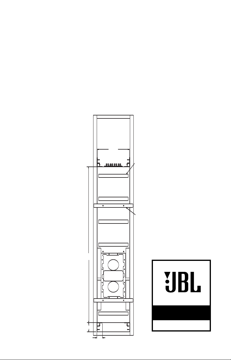
DAMPING
PADS
CENTERING
BARS
68.00
CABINET
4.00
2.49
14.00
CABINET
CHOOSING JBL
or more than 60 years, JBL has
F
been involved in every aspect of
usic and film recording and
m
eproduction, from live perform-
r
ances to monitoring the recordings
ou play in your home, car or
y
ffice.
o
e’re confident that the JBL
W
speaker and back box you have
chosen will provide every note of
njoyment that you expect – and
e
that when you think about pur-
hasing additional audio equip-
c
ent for your home, car or office,
m
you will once again choose JBL.
Please take a moment to register
your product on our Web site at
www.jbl.com. It enables us to keep
you posted on our latest advancements, and helps us to better
understand our customers and
build products that meet their
needs and expectations.
JBL Consumer Products
INCLUDED
SS88IWSBB
(1) SS88IWSBB back box
(shown installed between
16" on-center wall studs)
(4) L-brackets
(8) #10 32 x 1" screws
(L-brackets to back box)
(8) #10 split washers
(L-brackets to back box)
(8) #10 flat washers
(L-brackets to back box)
(8) #8 x 3/4" wood screws
(L-brackets to wall studs)
(2) wood centering bars
(4) #10 32 x 1-1/2" flat-head screws
(centering bars to back box)
NOTE: The back box is shipped with the
two centering bars attached to it using
the four flat-head screws.
SPEAKER
PLACEMENT
t is best to establish the locations
I
for the speakers in advance, to
void having to correct errors
a
fter installation has already
a
begun. Refer to these guidelines,
nd also see the owner’s guide for
a
he SS88IWS subwoofer for more
t
information.
It is generally recommended that
you install your SS88IWS in-wall
ubwoofer along the same wall
s
as the front loudspeakers. The
S88IWS subwoofer is not video-
S
hielded and should not be placed
s
ear a video display. Installing the
n
SS88IWS near a corner will tend
o maximize low-frequency output.
t
Be cautious when installing in a
corner, to avoid a “boomy” sound.
lso take into consideration any
A
unusual features of the room, such
s an alcove, which may tend to
a
reate a localized node that may
c
affect bass response in that area
f the room.
o
It is generally recommended that
he speaker be installed so that the
t
bottom of the speaker is approxi-
ately 12" from the floor. Note that
m
nstalling the speaker within the
i
SS88IWSBB back box as shown in
the illustration to the left will
achieve the recommended height.
This is to help with the low-frequency loading (bass reinforcement). This also helps hide the
speaker in a less visible place.
Remember that these are just
guidelines. Since every listening
room is different, JBL strongly recommends experimenting with the
positioning of your subwoofer prior
to cutting the wall to obtain the
most pleasing results in your room.
One technique that can help you
find the ideal subwoofer location
is to temporarily borrow a standalone subwoofer and place it near
the main listening location. Then
move around the room and determine where you hear the most
pleasing bass performance. This
would then be the ideal location
for the subwoofer.
PERFORMANCE
SPECIALIST
™
SS88IWSBB
OWNER’S GUIDE
®
Page 2
PEAKER
YEL/BLK
Y
EL
W
HT/BLK
WHT
O
RG/BLK
O
RG
GRE/BLK
GRE
INPUT 1
INPUT2
OUTPUT 1 OUTPUT 2
– + – + – + – +
– +– +
Receiver/Amplifier Speaker Outputs
Left Right
– +
Front Left Speaker
– +
Front Right Speaker
Connections Panel of
SS88IWSBB Back Box
Connection Method #1, Using One SS88IWS
With Back Box (Remove Shorting Straps)
– +– +
Receiver/Amplifier Speaker Outputs
L
eft Right
– +
Front Left Speaker
– +
Front Right Speaker
Y
EL/BLK
Y
EL
W
HT/BLK
W
HT
ORG/BLK
ORG
G
RE/BLK
G
RE
I
NPUT 1
INPUT2
O
UTPUT 1 OUTPUT 2
– + – + – + – +
Y
EL/BLK
Y
EL
W
HT/BLK
W
HT
ORG/BLK
ORG
G
RE/BLK
G
RE
I
NPUT 1
INPUT2
O
UTPUT 1 OUTPUT 2
– + – + – + – +
Connections Panel of
Left SS88IWSBB Back Box
Connections Panel of
Right SS88IWSBB Back Box
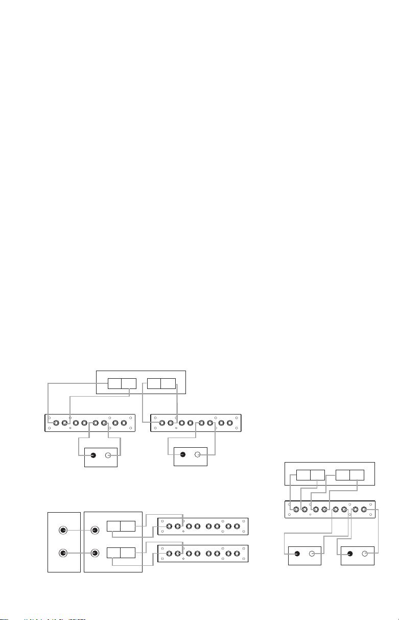
Connection Method #1, Using Two SS88IWS Loudspeakers
With Back Boxes (Use Shorting Straps)
– +
Amplifier
Receiver/Processor
Speaker-Level
Outputs
Subwoofer or
Main Amp
Out
Line-Level
Inputs
– +
Left Left
Right Right
Left
Right
Y
EL/BLK
YEL
WHT/BLK
W
HT
ORG/BLK
O
RG
G
RE/BLK
G
RE
INPUT 1
INPUT2
OUTPUT 1 OUTPUT 2
– + – + – + – +
YEL/BLK
YEL
WHT/BLK
WHT
ORG/BLK
ORG
GRE/BLK
GRE
INPUT 1
INPUT2
OUTPUT 1 OUTPUT 2
– + – + – + – +
Left SS88IWSBB Back Box
Right SS88IWSBB Back Box
Connection Method #2, Using Two SS88IWS Loudspeakers
With Back Boxes (Use Shorting Straps)
S
CONNECTIONS
Connection Tips
Refer to page 4 of the SS88IWS subwoofer owner’s guide for general
nformation on speaker-wire con-
i
nections. This manual includes connection guidelines that are specific
o the SS88IWSBB back box.
t
To use the push-type terminals on
he connections panel supplied with
t
the SS88IWSBB back box enclosure,
epress the colored cap until the
d
pass-through hole in the binding
post is revealed. While holding the
ap down, insert the bare end of
c
the wire, or a banana plug, into the
pass-through hole. Release the cap
and tug gently on the wire to ensure
that it is secure.
Since the SS88IWS is a passive
loudspeaker, only speaker-level connections are available. Depending
on whether you are using a dedicated subwoofer
main receiver/
SS88IWS, select one of the two connection methods that follow.
Connection Method #1
Use this method when you are
using the SS88IWS with your main
receiver/amplifier. Connect the main
amplifier or your
amplifier to power the
eft and right speaker-level outputs
l
n your receiver/amplifier to the
o
Input 1 (for left channel) and Input 2
for right channel) connectors on the
(
S88IWS connection panel. Connect
S
the Output 1 terminals to the corre-
ponding terminals on your front left
s
speaker, and the Output 2 terminals
to the corresponding terminals on
our front right speaker.
y
NOTE: When using Connection
ethod #1 with only one SS88IWS,
M
the shorting straps must be
removed.
If you are using two SS88IWS sub-
oofers, connect the left speaker out-
w
puts on your receiver/
amplifier to
Input 1 on one subwoofer’s connections panel, and the right speaker
outputs on your receiver/amplifier to
Input 1 on the second subwoofer’s
connections panel. Then connect
Output 1 from the leftwoofer to the inputs
channel sub-
on your main
left speaker, and Output 1 from the
right-channel subwoofer to the
inputs on your main right speaker.
When using the SS88IWS in this
mono mode, you should not remove
the shorting straps.
onnection Method #2
C
se this method when you are
U
using the SS88IWS with a dedicated
ubwoofer amplifier. Connect your
s
ain receiver/
m
subwoofer
nput on your subwoofer amplifier.
i
rocessor’s line-level
p
output to the line-level
Connect the speaker terminals on
your subwoofer amplifier to either
nput 1 or Input 2. If your amplifier
I
has stereo outputs, you may connect one channel to each of Inputs 1
nd 2. However, you must remove
a
the shorting straps when using
tereo mode. Alternatively, you may
s
onnect each channel to a separate
c
SS88IWS. When using only one
nput on an individual SS88IWS, you
i
should leave the shorting straps in
place.
Using the SS88IWSBB Back Box
Whichever connection method you
choose to install the SS88IWSBB
back box, you will need to connect
all of the eight wires coming out of
the bottom of the back box to the
appropriate terminals on the loudspeaker. The wires are color-coded
as follows:
INPUT 1 (–): Yellow with black
stripe
INPUT 1 (+): Solid yellow
INPUT 2 (–): White with black
stripe
INPUT 2 (+): Solid white
OUTPUT 1 (–): Orange with
black stripe
OUTPUT 1 (+): Solid orange
OUTPUT 2 (–): Green with black
stripe
OUTPUT 2 (+): Solid green
Page 3

INSTALLATION
See
Detail A
D
etail C
Detail B
Detail A
L
-Brackets
L
-Brackets
Centering Bar
Centering Bar
S
ee
D
etail A
See
D
etail B
See
Detail C
Although the JBL Performance
pecialist Series in-wall speakers
S
were designed to be easily
installed in existing construction
pplications, it is recommended
a
that installation of the SS88IWSBB
back box in new construction
e reserved for professionals.
b
See the manual for the SS88IWS
ubwoofer for instructions on
s
nstalling the speaker in existing
i
construction without using the
back box.
he SS88IWSBB back box is an
T
ptional installation accessory for
o
the SS88IWS in-wall subwoofer.
When used, the SS88IWSBB back
box is installed during new construction before the wallboard.
Installation
1. Using the four flat-head screws,
install the two centering bars as
shown in Detail B in the drawings. The centering bars are for
setting the depth of the enclosure. They also help locate the
left/right position of the enclosure as they can be mounted
into the studs on the left and
right to hold the enclosure in the
correct location before final
mounting.
Using the eight #10 32 x 1" screws,
2.
install the four L-brackets
four corners of the enclosure.
Each of the eight screws should
have both the split washer and
flat washer installed; the split
washer goes on first. Leave the
screws a half-turn loose at first
to allow for adjustment later
(see Detail A). Do not screw the
L-brackets into the wall studs at
this time (see step 6).
3. Fit the enclosure into the wall.
The bottom edge of the bottom
L-brackets will rest against the
baseboard two-by-four. At this
time, make note of adjustments
necessary to square the enclosure into the wall (see Detail C).
4. After refitting and tightening the
L-brackets into the enclosure
(but not the wall studs yet), fit
the enclosure into the wall once
again.
at the
At this time, you may want to
5.
screw through each side of the
wood centering bars to mount
the enclosure to the studs. This
will help hold the enclosure in
position before the L-brackets
are mounted to the studs.
6. Screw the L-brackets into the
studs, using the eight wood
crews.
s
. Remove the wood centering
7
bars and replace the flat-head
screws into the holes left over
(the holes left in the cabinet
face underneath the bars are
also counterbored to accept the
flat-head screws).
8. The enclosure is now installed
and ready for the wallboard to
be installed over it.
9. Make the connections from
your receiver/amplifier to the
SS88IWS back box connections
panel, and to any other speakers as appropriate for your system, following the instructions
on the previous page. Connect
the eight wires hanging from the
bottom of the SS88IWSBB back
box to the correct terminals on
the SS88IWS loudspeaker (see
the previous page).
Page 4

PECIFICATIONS
S
SS88IWSBB
abinet Dimensions (H x W x D):68" x 14" x 4" (1727mm x 356mm x 102mm)
C
Cabinet Weight: 39 lb (17.7 kg)
All features and specifications are subject to change without notice.
PRO SOUND
COMES HOME
OWNER’S GUIDE
PRODUCT LINE:
PERFORMANCE™SPECIALIST
MODEL:
JBL Consumer Products
250 Crossways Park Drive, Woodbury, NY 11797
8500 Balboa Boulevard, Northridge, CA 91329
516.255.4JBL (4525) www.jbl.com
© 2005 Harman International Industries, Incorporated. All rights reserved.
JBL and Harman International are registered trademarks, and Pro Sound
Comes Home and Performance Series are trademarks, of Harman
International Industries, Incorporated.
Part No. 361840-001
SS88IWSBB
™
 Loading...