

Page 1
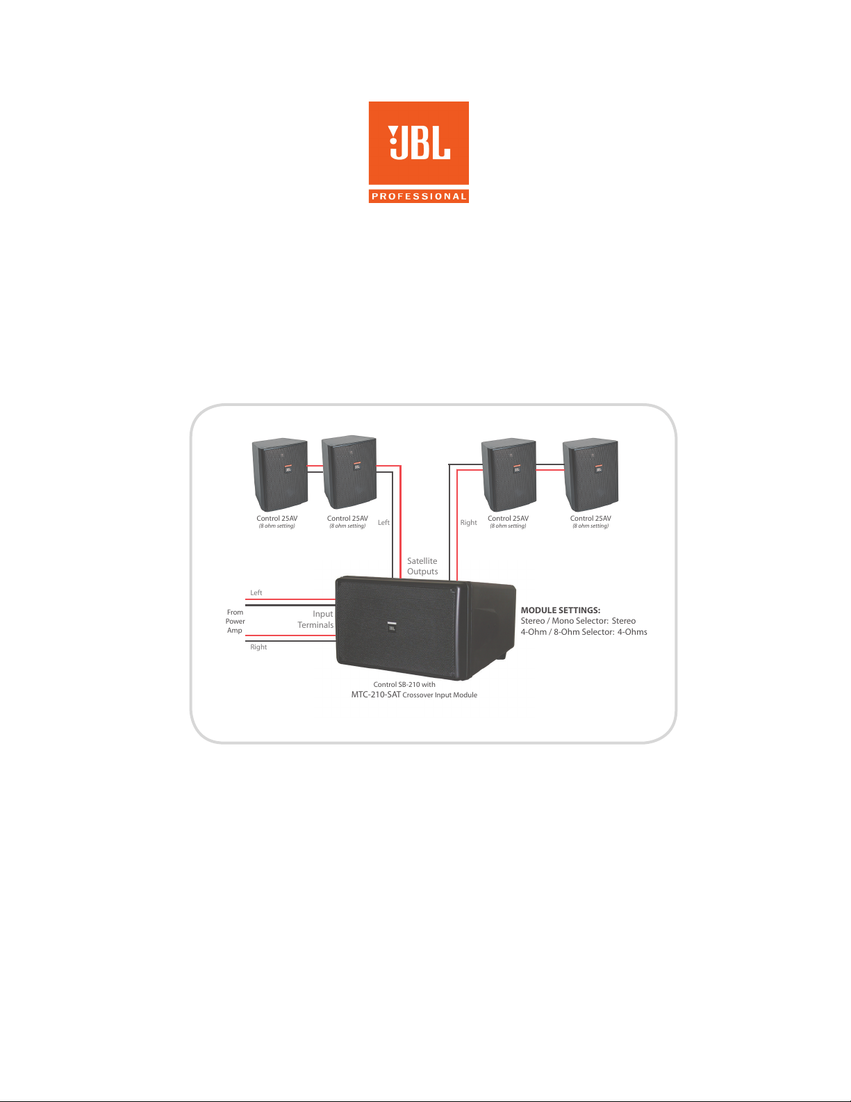
Satellite
Outputs
Left Right
System #5 in Stereo
SPL (at 20 Feet):
94 dB Continuous (peaks of 104 dB)
From
Power
Amp
Left
Right
MODULE SETTINGS:
Stereo / Mono Selector: Stereo
4-Ohm / 8-Ohm Selector: 4-Ohms
Input
Terminals
Control SB-210 with
MTC-210-SAT Crossover Input Module
Control 25AV
(8 ohm setting)
Control 25AV
(8 ohm setting)
Control 25AV
(8 ohm setting)
Control 25AV
(8 ohm setting)
APPLICATION GUIDE
Subwoofer-Satellite Systems
Using Control SB-210 & SB-2 Subwoofers
System #5 in Stereo Mode Shown
Using subwoofers and satellite loudspeakers with a pre-engineered passive crossover built into the
subwoofer can be a very effective way of achieving high-fidelity sound economically for applications
requiring greater bandwidth than is typically possible from full-range speakers alone.
When applied properly, small subwoofer-satellite systems – often referred to as “sub-sat” systems –
can provide high fidelity sound for a wide variety of applications, such as restaurants, retail stores,
hotels, music cafes, leisure venues, sports bars & lounges, fitness centers, themed applications, and
many more.
is guide provides recommended subwoofer-satellite configurations that work well together. In
addition, the Connection Information and System Design sections provide important information
for applying these subwoofer-satellite systems properly.
Page 2

Page 3

Table of Contents
SIX SUB-SAT SYSTEMS AT A GLANCE . . . . . . . . . . . . . . . . . . . . . . . . . . . . . . . . . . . . . . . . . . . . . 2
IMPORTANT SATELLITE CONNECTION INFORMATION . . . . . . . . . . . . . . . . . . . . . . . . . 3
SYSTEM CONSIDERATIONS
General Objectives . . . . . . . . . . . . . . . . . . . . . . . . . . . . . . . . . . . . . . . . . . . . . . . . . . . . . . . . . . . . . . . . . 4
Sensitivity Balance
Subwoofer Model Selection
Designing for Other JBL Subwoofer Models
System Design Considerations . . . . . . . . . . . . . . . . . . . . . . . . . . . . . . . . . . . . . . . . . . . . . . . . . . . . . . . . 5
Maximum SPL Listing
Subwoofer Location’s Affect on Sensitivity and Maximum SPL
Using the MTC-210-SAT Input Module -- 4 Ohm / 8 Ohm Setting, Mono / Stereo Setting,
Operation from a 70V/100V Distributed Speaker Line
Subwoofer Distance Consideration
Affect of Room Size
SYSTEM DIAGRAMS
Surface-Mount (On-Wall) Satellite Speakers
System #1 – CCS6000 System: 4 pcs Control 23 with Control SB-2 . . . . . . . . . . . . . . . . . . . . . . . . . . 7
System #2 – 2 pcs Control 25AV & Control SB-210 . . . . . . . . . . . . . . . . . . . . . . . . . . . . . . . . . . . . . . 8
System #3 – 2 pcs Control 28 & Control SB-210 . . . . . . . . . . . . . . . . . . . . . . . . . . . . . . . . . . . . . . . . 10
System #4 – 2 pcs Control 29AV-1 & Control SB-210 . . . . . . . . . . . . . . . . . . . . . . . . . . . . . . . . . . . . 12
System #5 – 4 pcs Control 25AV & Control SB-210 . . . . . . . . . . . . . . . . . . . . . . . . . . . . . . . . . . . . . 14
In-Ceiling Satellite Speakers (with Surface-Mount Subwoofer)
System #6 – 4 pcs Control 24C . . . . . . . . . . . . . . . . . . . . . . . . . . . . . . . . . . . . . . . . . . . . . . . . . . . . . . 16
Page 4
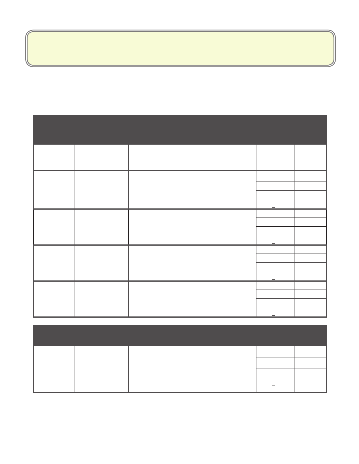
SUB-SAT SYSTEMS AT A GLANCE
Detailed Information About Each System and Application Guidelines are on the Following Pages.
System
Number Products Applications
Surface-Mount
Satellite Speakers
System 1
(CCS6000)
System 2 2 x Control 25AV
System 3 2 x Control 28
System 4 2 x C29AV-1
System 5 4 x Control 25AV
4 x Control 23
1 x SB-2
1 x SB210
1 x MTC-210-SAT
1 x SB210
1 x MTC-210-SAT
1 x SB210
1 x MTC-210-SAT
1 x SB210
1 x MTC-210-SAT
Light volume ambient music in
medium size spaces where four
speakers are needed.
Light to medium volume ambient
music in small to medium sized
spaces where two satellite speakers are enough to cover the area.
Medium volume ambient music in
small spaces where two satellite
speakers are enough to cover the
area.
High volume, high-delity music reproduction in small spaces
where two watellite speakers are
enough to cover the area.
Medium volume, high-delity music reproduction in larger spaces
where 4 satellite speakers are
needed to cover the area.
(On-Wall)
SPL
(Max Cont.
@ 20 ft)
Modes
Channel
87 dB Stereo Only 4Ω
91 dB
Mono 8Ω
Stereo 4Ω
70V/100V
(with MTC210T-SAT)
95 dB
Mono 8Ω
Stereo 4Ω
70V/100V
(with MTC210T-SAT)
96 dB
Mono 8Ω
Stereo 4Ω
70V/100V
(with MTC210T-SAT)
94 dB
Mono 8Ω
Stereo 4Ω
70V/100V
(with MTC210T-SAT)
Ω Per
Amp
n/a
n/a
n/a
n/a
In-Ceiling
Satellite Speakers
System 6
4 x Control 24C
1 x SB210
1 x MTC-210-SAT
(Mounting options for
subwoofer described in
System 6 text)
Medium to high volume music
reproduction where 4 in-ceiling
satellite speakers are needed
to cover the area.
96 dB
(at 10 feet)
2 3
Mono 8Ω
Stereo 4Ω
70V/100V
(with MTC210T-SAT)
n/a
Page 5
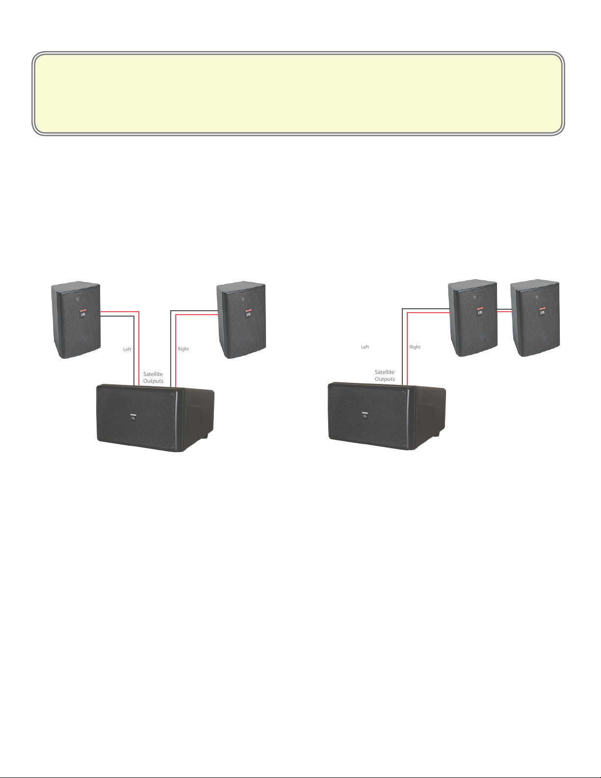
Important Satellite Connection Information
Satellite
Outputs
Right
Satellite
Outputs
RightLeft
Left
For Mono (& 70V Mono) Systems
For Mono systems, always connect half the satellite speakers to one of the satellite speaker output terminals and the other half to the
other satellite speaker output terminals. Do NOT connect to only one of the sets of satellite output terminals.
In order to avoid excessively low impedance loads to the power amp when using 4 satellite speakers (which could cause the power
amplifier to fail), the satellite output terminals of the SB-210 in mono mode are connected in series with each other. is requires
that speakers be connected to both sets of satellite output terminals, and that the load on each satellite output be matched.
Otherwise, there will be very little or no sound coming from the satellite speakers
CORRECT
For systems with 2 satellite speakers, put 1 on each set
of the subwoofer’s satellite output terminals (shown).
For systems with 4 satellite speakers, put 2 on each set
of the subwoofer’s satellite output terminal
WRONG
All satellite speakers on one of the sets of satellite
output terminals and none on the other satellite
output terminals.
Page 6

Sub-Sat System Design
e exact configuration of a subwoofer/satellite loudspeaker system depends on a number of factors, such as:
• How large the room is and how many satellite speakers it will take to cover the room?
• Whether the distance between the satellite speakers allows a single subwoofer to cover the entire space?
• Whether the program material is light background music or dominant driving music?
• Where the subwoofer will be located in relation to room boundaries (wall, ceiling, corners)?
e system recommendations in this guide and the performance figures are based on some baseline assumptions which will not be
correct for all applications. Adjustments may need to be made. A discussion of the considerations, baseline assumptions conditions and
possible adjustment requirements is below.
General Objectives
Sensitivity Balance
e volume balance between the subwoofer and the satellite
speakers in a passively crossed-over system is called sensitivity
balance.
Targets:
a) Sensitivity Balance – Typically, the way the human
hearing system works, the subwoofer needs to be 2 to 6
dB louder than the satellite speakers in order to sound
balanced. e subwoofer/satellite systems in this
guide are all structured to provide the proper range of
sensitivity balance with the subwoofer located on a flat
surface (wall, ceiling, floor). e sensitivity balance can
be altered, as required, via an active graphic equalizer.
e balance can also be altered by placing the subwoofer
closer to more boundary surfaces -- see the “Subwoofer
Location” section below for more about the effect of
positioning.
b) Maximum Sound Level Balance – It is desirable for
the subwoofer to be able to deliver adequate maximum
sound output capability to keep up with the satellite
speakers when they are driven at their maximum drive
level. e subwoofer output of these systems is high
enough to keep up with the satellite speakers at high
drive levels.
Subwoofer Model Selection
All the systems in this guide use the Control SB-210 subwoofer,
with the exception of the CCS6000 System, which uses the Control
SB-2 subwoofer. Passive crossover networks are built-into SB-2
and available for SB-210, making it easy to structure subwoofer-
satellite systems.
Designing for Other JBL Subwoofer Models
Other subwoofers from JBL Professional include Control 19CS
In-Ceiling Subwoofer and Control 312CS High Power In-Ceiling
Subwoofer. ese subwoofers are intended to be used in actively
crossed-over systems -- either contains a built-in passive crossover
network.
For determining the proper number of Control 19CS subwoofers,
use the Subwoofer Utility in the DSD Distributed System Design
software (free download located on the Software Download page
from the www.jblpro.com website).
For e Control 312CS subwoofer, use the “Control 300 Subwoofer
Ratio Guide” posted in the Control 300 section of the Technical
Library page on www.jblpro.com website.
4 5
Page 7

Sub-Sat Design Considerations
Sound Level Capability
For each system in this guide, the Max SPL figure is listed,
describing the continuous sound level that the system can
maintain on a full-range basis with either speech or music
program content, with 10 dB headroom for clear transient
peaks.
For any installation, the satellite speakers might be located
next to each other and cover exactly the same area, resulting
in 6 dB of coupling between them, or they might be located
far apart and have no overlap between then resulting in no
coupling. e Max SPL figures listed in the charts assume
somewhere in between, that there is some degree of overlap
in coverage but not full overlap. erefore, a coupling figure
of 3 dB is utilized.
Actual Max SPL
For applications where there is very little overlap of satellite
speakers, the actual Maximum SPL will be 3 dB lower for
2 satellite speakers (and 6 dB lower for 4 satellite speaker)
than what is listed. For applications where there is almost
full overlap (satellite speakers covering the same area), the
actual Maximum SPL will be 3 dB higher for 2 satellite
speakers (and 6 dB higher for 4 satellite speakers).
4 Ohm / 8 Ohm Setting
(ie, Satellite Speaker Impedance Selector)
e module contains a header adjustment for setting the crossover
to work properly with either 4 ohm or 8 ohm satellite loads per
output.
Mono / Stereo Setting
e module also contains a header to set the system to operate
either as a mono system with a single input (+ and -) wired to
the Left/Mono input terminals, or as a full stereo system with
Left input wired to Left input terminals and right input wired to
Right input terminals.
Subwoofer Location’s Affect on Sensitivity
and Maximum SPL
e system performance figures listed are based on the
subwoofer being located away from boundary junctions
and corners. For applications where the subwoofer will be
placed at a 2-surface boundary junction (wall/floor, wall/
ceiling, wall/wall), both the Sensitivity and the Maximum
SPL of the subwoofer increases by 6 dB. For applications
where the subwoofer is placed as a corner junction (wall/
wall/ceiling or wall/wall/floor), the Sensitivity and the
Maximum SPL of the subwoofer increases by 12 dB.
is can unbalance the subwoofer satellite sensitivity
balance. It is a good idea to have an equalizer in the sound
system to be able to adjust the bass level for proper balance.
A parametric EQ allows for the best adjustment. For
graphic EQ, a minimum of 15 bands is usually required to
be able to set the EQ break point at the proper frequency.
Using the MTC-210-SAT Input Module
ALL these systems (except the CCS6000 System that utilizes
a SB-2 subwoofer) utilize the MTC-210-SAT input module
installed in the back of the Control SB-210 subwoofer.
is module provides a full passive crossover consisting
of a high-pass to the satellite speakers and low-pass to the
subwoofer drivers.
Figure 1
Setting Mono/Stereo and Satellite Impedance Headers
on MTC-210-SAT (and MTC-210T-SAT) Input Module
Mono/Stereo and 4/8 Ohm selection is accomplished by
moving the headers on the MTC-210-SAT Input Module before
installing the module into the subwoofer. Yellow indicators move
with the headers, annunciating the selected modes visibly on the
back panel of the subwoofer after the module is installed. Header
positions shown in the picture above are set to Mono with 4
ohms per channel of satellite speakers. Moving the headers in the
position of the red arrows changes the settings to Stereo with 8
ohms per channel of satellite speakers.
Operation from a 70V/100V Distributed
Speaker Line
A different SB-210 input module needs to be purchased for
operating a subwoofer satellite system via 70V/100V. It is model
MTC-210T-SAT, which includes input 70V/100V transformers
as well as the built-in crossover network.
Speaker Type for 70V/100V Systems
Satellite speakers remain LOW-IMPEDANCE (non-T)
models. DO NOT use T-version satellite speakers for any
of the satellite speakers, even those systems operated from a
70V/100V distributed speaker line.
Page 8
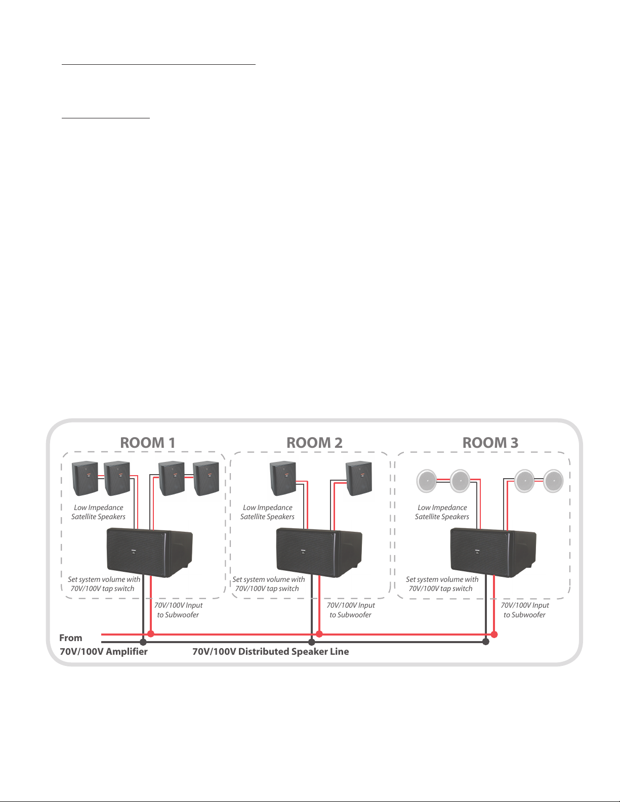
Adjusting Volume of 70V/100V System
Low Impedance
Satellite Speakers
Set system volume with
70V/100V tap switch
Low Impedance
Satellite Speakers
ROOM 1 ROOM 2 ROOM 3
70V/100V Distributed Speaker Line
70V/100V Input
to Subwoofer
70V/100V Input
to Subwoofer
Set system volume with
70V/100V tap switch
70V/100V Input
to Subwoofer
Set system volume with
70V/100V tap switch
Low Impedance
Satellite Speakers
70V/100V Amplifier
From
Adjust the tap setting to change the amount of power that
gets to the entire sub/sat system.
Multiple Systems
Multiple sub-sat systems can be utilized on a single
70V/100V distributed speaker line. Each can cover a
different area with full-range sound. Systems can be mixed
on a 70V/100V line as long as all the systems utilized the
MTC-210T-SAT module. See Figure 2.
Subwoofer Distance Consideration
Even though it’s not easy for the human ear to tell where the
sound from a subwoofer is coming from (non-localizable),
that doesn’t mean that a single subwoofer can always cover
an entire space.
e sound level from a subwoofer is louder nearby to the
subwoofer and quieter farther away from it. As rooms
get larger the level variation gets more uneven because the
distance from the subwoofer gets longer. It may be necessary
to add a second subwoofer on the other side of the room.
Locating multiple subwoofers near the center of opposite
walls within the room often works well, resulting in more
even coverage of the entire room.
When greater subwoofer output is desired, an alternative is
to locate the subwoofers near opposite corners of the room,
although the subwoofers can get excessively loud in those corners
compared to the rest of the room.
For rooms where very even subwoofer coverage is desired, a
distributed subwoofer system might be a better solution than using
one of the passive subwoofer/satellite systems from this guide. If
so, see the subwoofer chapter of the JBL guide entitled Designing
Better Sounding In-Ceiling Business Music Systems.
Affect of Room Size on Sound Level
e Max SPL figures listed for each system are based on a listening
distance of approximately 20 feet.
For larger rooms where some listeners will be father than 20 feet
from the speakers, the true sound level capability of the sub-sat
system will be lower. For example, the Max SPL level at 40 feet
-- twice the listening distance -- will be 6 dB lower than the listed
figure.
In addition, as the room gets larger, there will be more level variation
of the sound from both the satellite speakers and the subwoofer
from place to place within the room. is can lead to unacceptably
high variations in sound level, where the sound might be too loud
in some areas and too soft in others.
In rooms where this is the case, it may be necessary to utilize
more than one subwoofer/satellite system, or to use a more highly
distributed system than a small subwoofer/satellite system is
capable of doing.
6 7
Figure 2
Multiple 70V/100V sub-sat systems on a single distributed speaker line.
Page 9

Systems with SURFACE-MOUNT (on-wall)
Satellite
Outputs
Left Right
CCS6000 System (Stereo Only)
SPL (at 20 Feet):
84 dB Continuous (peaks of 94 dB)
From
Power
Amp
Left
Right
Input
Terminals
Control SB-2
Control 23 Control 23Control 23Control 23
Satellite Speakers
System #1: CCS6000 System
4 pcs Control 23 with Control SB-2
Application
Light volume ambient music in medium size spaces where
four speakers are needed.
Max Continuous Average SPL (at 20 feet)
87 dB (with peaks of 97 dB)
Stereo/Mono Capability
Works best as a stereo system with separate input for left and
right inputs.
Connection
Connect 2 pcs of Control 23 to each satellite
output (Left and Right). Do NOT connect all
4 satellite speakers to a single satellite output.
Application Note:
is combination produces a great full-range sound with flat
frequency response, usable from 38 Hz to 22 kHz.
Do NOT use a different quantity or model of satellite
speaker. Changing to a different, higher sensitivity, satellite
model unbalances the subwoofer/satellite sensitivity balance
(see “Consideration” notes above), resulting in the mids and
highs being overly dominant. Similarly, changing to fewer
Control 23 speakers results in a different load impedance
resulting in incorrect crossover point. is system works
properly only with 4 pcs Control 23 speakers – they were
designed to be used together.
Stereo System Connection Note
Ensure that the polarity hookup of the left and right inputs is correct.
If one of the inputs is connected backwards (out of polarity), the sub-
woofer will not produce much (if any) bass.
Page 10
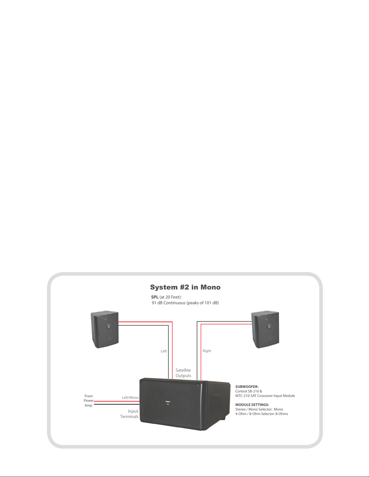
System #2
Satellite
Outputs
Left
Right
System #2 in Mono
SPL (at 20 Feet):
91 dB Continuous (peaks of 101 dB)
From
Power
Amp
Left/Mono
SUBWOOFER:
Control SB-210 &
MTC-210-SAT Crossover Input Module
MODULE SETTINGS:
Stereo / Mono Selector: Mono
4-Ohm / 8-Ohm Selector: 8-Ohms
Input
Terminals
2 pcs Control 25AV & Control SB-210
Application: Light to medium volume ambient music in
small to medium sized spaces where two satellite speakers are
enough to cover the area. is system produces excellent high
fidelity sound quality with very strong bass.
Max Continuous Average SPL (at 20 feet): 91 dB (with
peaks of 101 dB)
Max Output Balance -- e subwoofer has substantially
higher maximum output capability than the satellite speakers,
so this system has the capability of optionally being utilized in
applications where the bass will be EQ’d substantially higher
than the mids and highs. e system also works fine for flat-response applications.
Lower-Cost Option: Less expensive Control 25 speakers
can be utilized instead of Control 25AV for a more cost-effective system. e system will have slightly lower overall fidelity,
but will get 1 dB louder.
4 Ohm / 8 Ohm Setting: 8 Ohms
Stereo/Mono Capability: Either setting can be utilized.
Connection Diagrams
Connection:
Mono Operation – Connect input to the LEFT/MONO
input terminal. Put Stereo/Mono header into MONO
position. Connect 1 pc of Control 25AV to each satellite
output (LEFT and RIGHT). Do NOT connect both satellite speakers to a single satellite output.
Stereo Operation – Connect left and right inputs to the
LEFT and RIGHT input terminals. Put Stereo/Mono
header into STEREO position. Connect 1 pc of Control
25AV to each of the Satellite Outputs (LEFT and RIGHT)
8 9
Page 11

Satellite
Outputs
Left Right
System #2 in Stereo
SPL (at 20 Feet):
91 dB Continuous (peaks of 101 dB)
From
Power
Amp
Left
Right
MODULE SETTINGS:
Stereo / Mono Selector: Stereo
4-Ohm / 8-Ohm Selector: 8-Ohms
Input
Terminals
Control SB-210 with
MTC-210-SAT Crossover Input Module
Control 25AV
(8 ohm setting)
Control 25AV
(8 ohm setting)
Satellite
Outputs
Left
Right
System #2 on 70V/100V Distributed Line
SPL (at 20 feet):
At 250W Tap: 86 dB Continuous (96 dB peak)
At 125W Tap: 83 dB Continuous (93 dB peak)
At 78W Tap: 80 dB Continuous (90 dB peak)
From
70V or 100V
Power
Amp
Left/Mono
Input
Terminals
Control SB-210 with
MTC-210T-SAT Crossover Input Module
MODULE SETTINGS:
Stereo / Mono Selector: Mono
4-Ohm / 8-Ohm Selector: 8-Ohms
Stereo System Connection Note
Ensure that the polarity hookup of the left and right inputs is correct.
If one of the inputs is connected backwards (out of polarity), the sub-
woofer will not produce much (if any) bass.
Page 12
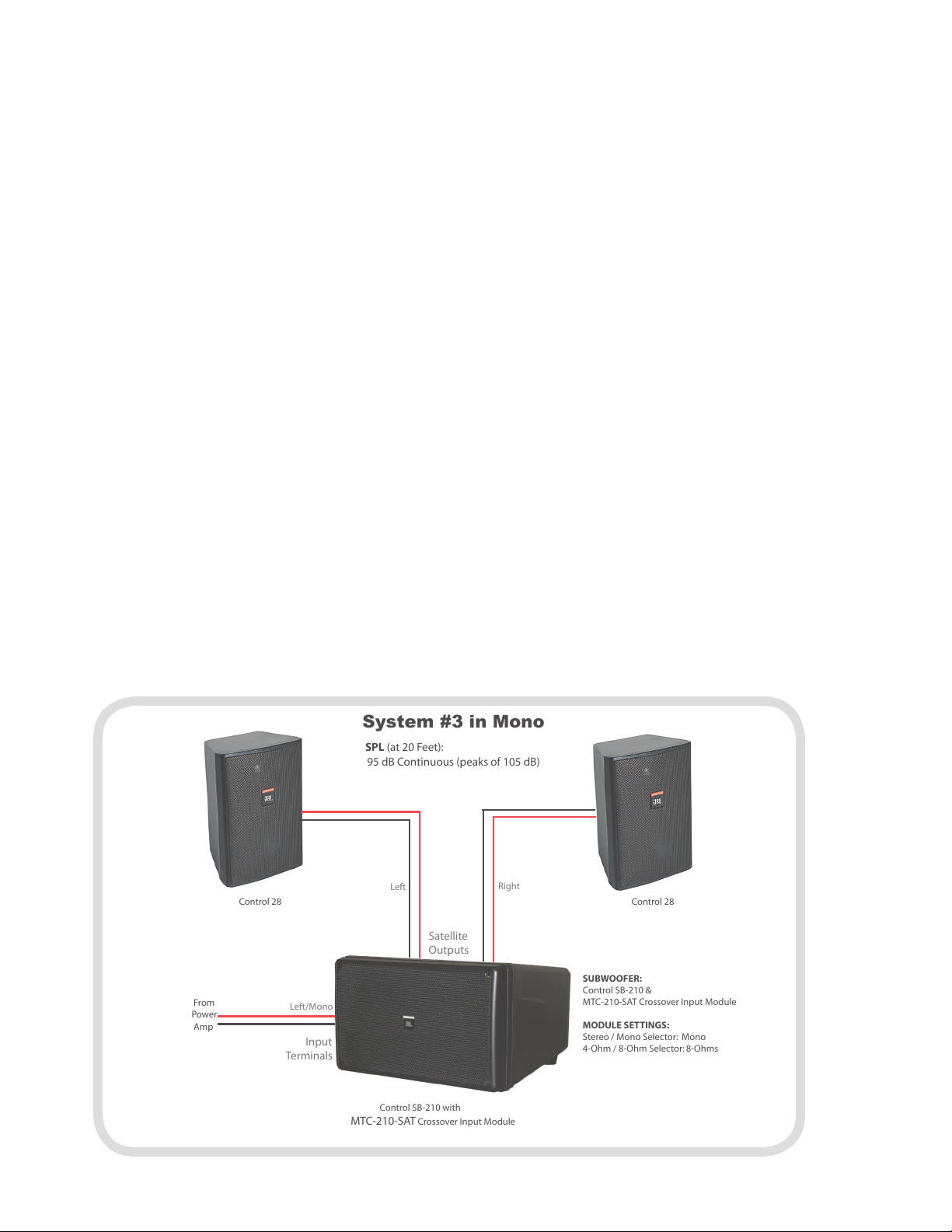
System #3
Satellite
Outputs
Left
Right
System #3 in Mono
SPL (at 20 Feet):
95 dB Continuous (peaks of 105 dB)
From
Power
Amp
Left/Mono
SUBWOOFER:
Control SB-210 &
MTC-210-SAT Crossover Input Module
MODULE SETTINGS:
Stereo / Mono Selector: Mono
4-Ohm / 8-Ohm Selector: 8-Ohms
Input
Terminals
Control 28 Control 28
Control SB-210 with
MTC-210-SAT Crossover Input Module
2 pcs Control 28 & Control SB-210
Application: Medium volume ambient music in small
spaces where two satellite speakers are enough to cover the area.
Max Continuous Average SPL (at 20 feet): 95 dB (with
peaks of 105 dB)
Max Output Balance -- e subwoofer has higher
maximum output capability than the satellite speakers, so this
system has the capability of being utilized for applications
where the bass will be EQ’d substantially higher than the
mids and highs. e system also works fine for flat-response
applications.
4 Ohm / 8 Ohm Setting: 8 Ohms
Stereo/Mono Capability: Either setting can be utilized
Connection Diagrams
Connection:
Mono Operation – Connect input to the LEFT input
terminal. Put Stereo/Mono header into MONO position.
Connect 1 pc of Control 28 to each satellite output (LEFT
and RIGHT). Do NOT connect both satellite speakers to
a single satellite output.
Stereo Operation – Connect left and right inputs to the
LEFT and RIGHT input terminals. Put Stereo/Mono
header into STEREO position. Connect 1 pc of Control
28 to each of the Satellite Outputs (LEFT and RIGHT)
10 11
Page 13
Satellite
Outputs
Left
Right
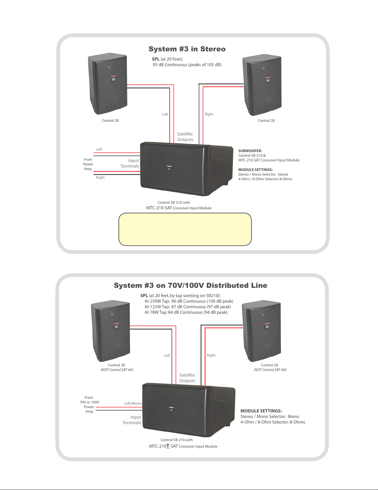
System #3 in Stereo
SPL (at 20 Feet):
95 dB Continuous (peaks of 105 dB)
SUBWOOFER:
Control SB-210 &
MTC-210-SAT Crossover Input Module
MODULE SETTINGS:
Stereo / Mono Selector: Stereo
4-Ohm / 8-Ohm Selector: 8-Ohms
Control 28 Control 28
Control SB-210 with
MTC-210-SAT Crossover Input Module
From
Power
Amp
Left
Right
Input
Terminals
Satellite
Outputs
Left
Right
System #3 on 70V/100V Distributed Line
SPL (at 20 feet, by tap seetting on SB210):
At 250W Tap: 90 dB Continuous (100 dB peak)
At 125W Tap: 87 dB Continuous (97 dB peak)
At 78W Tap: 84 dB Continuous (94 dB peak)
From
70V or 100V
Power
Amp
Left/Mono
Input
Terminals
Control SB-210 with
MTC-210T-SAT Crossover Input Module
MODULE SETTINGS:
Stereo / Mono Selector: Mono
4-Ohm / 8-Ohm Selector: 8-Ohms
Control 28
(NOT Control 28T-60)
Control 28
(NOT Control 28T-60)
Stereo System Connection Note
Ensure that the polarity hookup of the left and right inputs is correct.
If one of the inputs is connected backwards (out of polarity), the sub-
woofer will not produce much (if any) bass.
Page 14

Satellite
Outputs
Left
Right
System #4 in Mono
SPL (at 20 Feet):
96 dB Continuous (peaks of 106 dB)
From
Power
Amp
Left/Mono
SUBWOOFER:
Control SB-210 &
MTC-210-SAT Crossover Input Module
MODULE SETTINGS:
Stereo / Mono Selector: Mono
4-Ohm / 8-Ohm Selector: 8-Ohms
Input
Terminals
Control SB-210 with
MTC-210-SAT Crossover Input Module
Control 29AV-1
(8 Ohm Setting)
Control 29AV-1
(8 Ohm Setting)
System #4
2 pcs Control 29AV & Control SB-210
Application
High volume, high-fidelity music reproduction in small spaces
where two satellite speakers are enough to cover the area.
Max Continuous Average SPL (at 20 feet)
96 dB (with peaks of 106 dB)
4 Ohm / 8 Ohm Setting
8 Ohms
Stereo/Mono Capability
Either setting can be utilized
Connection Diagrams
Connection
Mono Operation – Connect input to the LEFT input
terminal. Put Stereo/Mono header into MONO position.
Connect 1 pc of Control 28 to each satellite output (LEFT
and RIGHT). Do NOT connect both satellite speakers to
a single satellite output.
Stereo Operation – Connect left and right inputs to the
LEFT and RIGHT input terminals. Put Stereo/Mono
header into STEREO position. Connect 1 pc of Control
28 to each of the Satellite Outputs (LEFT and RIGHT)
Application Note
e Control 29AV-1 has the highest sensitivity (sound output
per watt of input) of any of the satellite speakers in this guide,
resulting in the bass from the subwoofer being lower, in relative
sense, than some of the other sub/sat systems. For more
dominant bass, additional subwoofer sensitivity can be attained
by corner-loading the subwoofer (see “Sensitivity Balance”
section, above). Alternatively, the subwoofer/satellite sensitivity
balance can be altered with an in-line active equalizer.
12 13
Page 15

Satellite
Outputs
Left Right
System #4 in Stereo
SPL (at 20 Feet):
96 dB Continuous (peaks of 106 dB)
From
Power
Amp
Left
Right
MODULE SETTINGS:
Stereo / Mono Selector: Stereo
4-Ohm / 8-Ohm Selector: 8-Ohms
Input
Terminals
Control SB-210 with
MTC-210-SAT Crossover Input Module
Control 29AV-1
(8 Ohm Setting)
Control 29AV-1
(8 Ohm Setting)
Satellite
Outputs
Left
Right
SPL (at 20 feet, by tap seetting on SB210):
At 250W Tap: 91 dB Continuous (101 dB peak)
At 125W Tap: 88 dB Continuous (98 dB peak)
At 78W Tap: 85 dB Continuous (95 dB peak)
From
70V or 100V
Power
Amp
Left/Mono
Input
Terminals
Control SB-210 with
MTC-210T-SAT Crossover Input Module
MODULE SETTINGS:
Stereo / Mono Selector: Mono
4-Ohm / 8-Ohm Selector: 8-Ohms
Control 29AV
(set to 8 ohms)
Control 29AV
(set to 8 ohms)
System #4 on 70V/100V Distributed Line
Ensure that the polarity hookup of the left and right inputs is correct.
If one of the inputs is connected backwards (out of polarity), the sub-
woofer will not produce much (if any) bass.
Stereo System Connection Note
Page 16

Satellite
Outputs
Left Right
System #5 in Mono
SPL (at 20 Feet):
94 dB Continuous (peaks of 104 dB)
MODULE SETTINGS:
Stereo / Mono Selector: Mono
4-Ohm / 8-Ohm Selector: 4-Ohms
Control SB-210 with
MTC-210-SAT Crossover Input Module
Control 25AV
(8 ohm setting)
Control 25AV
(8 ohm setting)
Control 25AV
(8 ohm setting)
Control 25AV
(8 ohm setting)
From
Power
Amp
Left/Mono
Input
Terminals
System #5
4 pcs Control 25AV & Control SB-210
Application
Medium volume, high-fidelity music reproduction where 4
satellite speakers are needed to cover the area.
Max Continuous Average SPL (at 20 feet)
94 dB (with peaks of 104 dB)
Max Output Balance
e subwoofer has higher maximum output capability than
the satellite speakers and the output capability can be further
boosted by placing the subwoofer at a boundary junction or
corner. is system has the capability of being utilized for
applications where the bass will be EQ’d substantially higher
than the mids and highs. e system also works fine for flatresponse applications.
4 Ohm / 8 Ohm Setting
4 Ohms
Stereo/Mono Capability
Either setting can be utilized
Connection
Mono Operation – Connect input to the LEFT input termi-
nal. Put Stereo/Mono header into MONO position. Connect 2 pcs of Control 25AV to each satellite output (LEFT
and RIGHT). Do NOT connect all 4 satellite speakers to
a single satellite output.
Stereo Operation – Connect left and right inputs to the
LEFT and RIGHT input terminals. Put Stereo/Mono
header into STEREO position. Connect 2 pcs of Control
25AV to each of the Satellite Outputs (LEFT and RIGHT)
Application Notes
Balance -- e subwoofer has higher maximum output
capability than the satellite speakers and the output
capability can be further boosted by placing the subwoofer
at a boundary junction or corner. is system has the
capability of being utilized for applications where the bass
will be EQ’d substantially higher than the mids and highs.
e system also works fine for flat-response applications.
Variations -- Control 25 speakers can be utilized instead of
Control 25AV for a more cost-effective system, resulting in
slightly lower overall fidelity, but 1 dB louder SPL.
Connection Diagrams
14 15
Page 17

Satellite
Outputs
System #5 on 70V/100V Distributed Line
SPL (at 20 feet, by tap setting on SB210):
At 250W Tap: 94 dB Continuous (104 dB peak)
At 125W Tap: 91 dB Continuous (101 dB peak)
At 78W Tap: 88 dB Continuous (98 dB peak)
From
70V or 100V
Power
Amp
Left/Mono
Input
Terminals
Control SB-210 with
MTC-210T-SAT Crossover Input Module
MODULE SETTINGS:
Stereo / Mono Selector: Mono
4-Ohm / 8-Ohm Selector: 4-Ohms
Left Right
Control 25AV
(8 ohm setting)
Control 25AV
(8 ohm setting)
Control 25AV
(8 ohm setting)
Control 25AV
(8 ohm setting)
Satellite
Outputs
Left Right
System #5 in Stereo
SPL (at 20 Feet):
94 dB Continuous (peaks of 104 dB)
From
Power
Amp
Left
Right
MODULE SETTINGS:
Stereo / Mono Selector: Stereo
4-Ohm / 8-Ohm Selector: 4-Ohms
Input
Terminals
Control SB-210 with
MTC-210-SAT Crossover Input Module
Control 25AV
(8 ohm setting)
Control 25AV
(8 ohm setting)
Control 25AV
(8 ohm setting)
Control 25AV
(8 ohm setting)
Stereo System Connection Note
Ensure that the polarity hookup of the left and right inputs is correct.
If one of the inputs is connected backwards (out of polarity), the sub-
woofer will not produce much (if any) bass.
Page 18

Satellite
Outputs
Left
Right
System #6 in Mono
SPL (at 10 Feet):
96 dB Continuous (peaks of 106 dB)
From
Power
Amp
Left/Mono
SUBWOOFER:
Control SB-210 &
MTC-210-SAT Crossover Input Module
MODULE SETTINGS:
Stereo / Mono Selector: Mono
4-Ohm / 8-Ohm Selector: 8-Ohms
Input
Terminals
Control SB-210 with
MTC-210-SAT Crossover Input Module
Control 24C
Control 29AV-1
(8 Ohm Setting)
Control 24C Control 24C Control 24C
Systems with
IN-CEILING Satellite Speakers
In-ceiling loudspeakers can benefit from the addition of a subwoofer. Often that takes the form factor of an in-ceiling subwoofer like
Control 19CS or Control 312CS, but it may be desirable to use a subwoofer with a full passive crossover. For more information
about model selection, see the “Subwoofer Model Selection” and “Designing for Other JBL Subwoofer Models” sections, above.
e SB-210 with MTC-210-SAT module is a subwoofer that contains a built in passive crossover, which makes it easy to structure
subwoofer/satellite systems. With in-ceiling satellite speakers, the SB-210 can be mounted on a wall or ceiling via the MTC-210U Ubracket, suspended from the ceiling via built-in suspension points, or installed above an air grate grille in the ceiling.
System #6
4 pcs Control 24C with Control SB-210
Application: Medium volume, high-fidelity music
reproduction where 4 in-ceiling satellite speakers are needed
to cover the area.
Max Continuous Average SPL (at 10 feet): 96 dB
(with peaks of 106 dB).
4 Ohm / 8 Ohm Setting: 4 Ohms.
Stereo/Mono Capability: Either setting can be utilized
Connection
Mono Operation – Connect input to the LEFT input termi-
nal. Put Stereo/Mono header into MONO position. Connect 2 pcs of Control 24C to each satellite output (LEFT
and RIGHT). Do NOT connect all 4 satellite speakers to
a single satellite output.
Stereo Operation – Connect left and right inputs to the
LEFT and RIGHT input terminals. Put Stereo/Mono
header into STEREO position. Connect 2 pcs of Control
24C to each of the Satellite Outputs (LEFT and RIGHT)
16 17
Page 19

Satellite
Outputs
System #6 on 70V/100V Distributed Line
From
70V or 100V
Power
Amp
Left/Mono
Input
Terminals
Control SB-210 with
MTC-210T-SAT Crossover Input Module
MODULE SETTINGS:
Stereo / Mono Selector: Mono
4-Ohm / 8-Ohm Selector: 8-Ohms
Left
Right
Control 24C Control 24C Control 24C Control 24C
Satellite
Outputs
System #6 in Stereo
SPL (at 10 Feet):
96 dB Continuous (peaks of 106 dB)
From
Power
Amp
Left
Right
MODULE SETTINGS:
Stereo / Mono Selector: Stereo
4-Ohm / 8-Ohm Selector: 8-Ohms
Input
Terminals
Control SB-210 with
MTC-210-SAT Crossover Input Module
Control 29AV-1
(8 Ohm Setting)
Control 29AV-1
(8 Ohm Setting)
Left
Right
Control 24C Control 24C Control 24C Control 24C
Stereo System Connection Note
Ensure that the polarity hookup of the left and right inputs is correct.
If one of the inputs is connected backwards (out of polarity), the sub-
woofer will not produce much (if any) bass.
Page 20

JBL Professional
8500 Balboa Boulevard, P.O. Box 2200
Northridge, California 91329 U.S.A.
A Harman International Company
© Copyright 2006 JBL Professional
CC Sub Sat
11/06
 Loading...