

Page 1

SYNTHESIS®THREE ARRAY
SAM3HA,
SAM3VA
™
OWNER
’
S AND
INSTALLER
MANUAL
’
S
Page 2

CONTENTS
TRODUCTION
IN
PEAKER PLACEMENT .............................................................................................................................................4
S
EFT AND RIGHT SPEAKERS ..............................................................................................................................4
L
C
A
......................................................................................................................................................3
ENTER CHANNEL SPEAKERS ...........................................................................................................................4
BIENTSURROUNDSPEAKERS
M
5.1-C
HANNEL SYSTEMS ..........................................................................................................................5
HANNEL SYSTEMS ..........................................................................................................................5
6.1-C
HANNEL SYSTEMS ..........................................................................................................................6
7.1-C
.......................................................................................................................5
REP
P
THE
SPEAKERS
ARING THE
ONNECTING
C
ROUBLESHOOTING.................................................................................................................................................9
T
PECIFICATIONS...................................................................................................................................................10
S
TO THE
RESTOFYOUR SYSTEM.........................................................................................6
HOOKUP WIRE .........................................................................................................................6
2
Page 3

INTRODUCTION
Congratulations on purchasing this JBL Synthesis®Three Array™home theater speaker. This product represents the
synthesis of everything that JBL has learned about the emotional power of audio and video in sixty years of preeminence in the field. It sets new benchmarks in the use of “high technology” and provides you with the experience of
being in some of the world’s greatest movie houses and concert halls, right at home! JBL’s Synthesis Three Array
speaker systems feature the following:
THX ULTRA2™-LICENSED HOME AUDIO SYSTEM: When used with a THX
speaker system will deliver a state-of-the-art THX home theater experience to your living room. You will hear in your
home exactly what the director and sound engineer heard in the recording studio. The system will reproduce the
audio flawlessly and without distortion.
ULTRAHIGH-FREQUENCY COMPRESSION DRIVER: 1" (25mm) Pure-titanium compression driver with aluminum
edge-wound voice coil and 2" (51mm) neodymium motor assembly
high-frequency response to exceed SACD™and DVD-Audio specifications.
, mounted in a constant-directivity horn for extended
High-Power Compression Horn: Horns are commonplace in movie theaters across the world, because of
their high power handling and well-defined high-frequency output. The horns employed in SAM3 have very low distortion, and a well-controlled directivity, to put the dialogue at the center of the screen and the effects all around you.
ACCURATE MID-BASS DRIVERS AND SUBWOOFERS: The 6-1/2" (165mm) mid-bass drivers incorporate many
of JBL’s patented technologies – such as Symmetrical Field Geometry
(SIM) and Vented Gap Cooling
midrange sound without harshness, stridency or listener fatigue. From two to as many as four 12" or 15" (305mm or
380mm) high-power subwoofers complete the experience with earth-shattering, deep bass.
™
(VGC) – as well as unique cone and dome materials, to provide tight, smooth
™
(SFG), Symmetrical Inductance Modulation
®
controller and amplifiers, your
COMMON VOICING: Synthesis Three Array uses common voicing across the front three channels. Since identical
drivers are used, each speaker has the same tonal qualities, thus as a sound is panned from one side to the other,
there will be no change in timbre.
MAGNETIC SHIELDING: All front speakers are magnetically shielded, allowing you to place them near video mon-
itors without generating interference or distorting the picture.
DUAL “INSIDE” NEODYMIUM, SHIELDED MOTOR STRUCTURE: The magnetic material is placed at the
center of the motor structure, INSIDE the voice coil diameter. This inverted dual-magnet configuration improves
magnetic shielding even further, reducing the extraneous magnetic field, and offers increased acoustic output.
DEEP-ANODIZED CONE
together with the motor features, helps to reduce midband distortions to very low levels (approximately 50dB to 60dB
below the fundamental signal driven at 100dB output).
AND
DOME MA
: The special deep-anodized aluminum cone and dome material,
TERIAL
TWO-STAGE PHASE PLUG: The phase plug is a key element in this compression driver. The accuracy of the phase
plug geometry is most important to achieve a wide and flat frequency response. The pressure distribution in the phase
plug is manipulated by adjustments to the number and width of the slots and even the plug inside streamline is optimized to achieve a coherent pressure front across the operating range at the exit of the phase plug.
SYMMETRICAL INDUCTANCE MODULATION (SIM): The flux-stabilizing ring and copper gap ring are also opti-
” Minimizing this
mized for size and position, to help minimize or eliminate “asymmetrical inductance modulation
asymmetrical inductance modulation leads to even further distortion reduction and improved vocal clarity
.
.
3
Page 4
RCL
VIEWING
POSITION
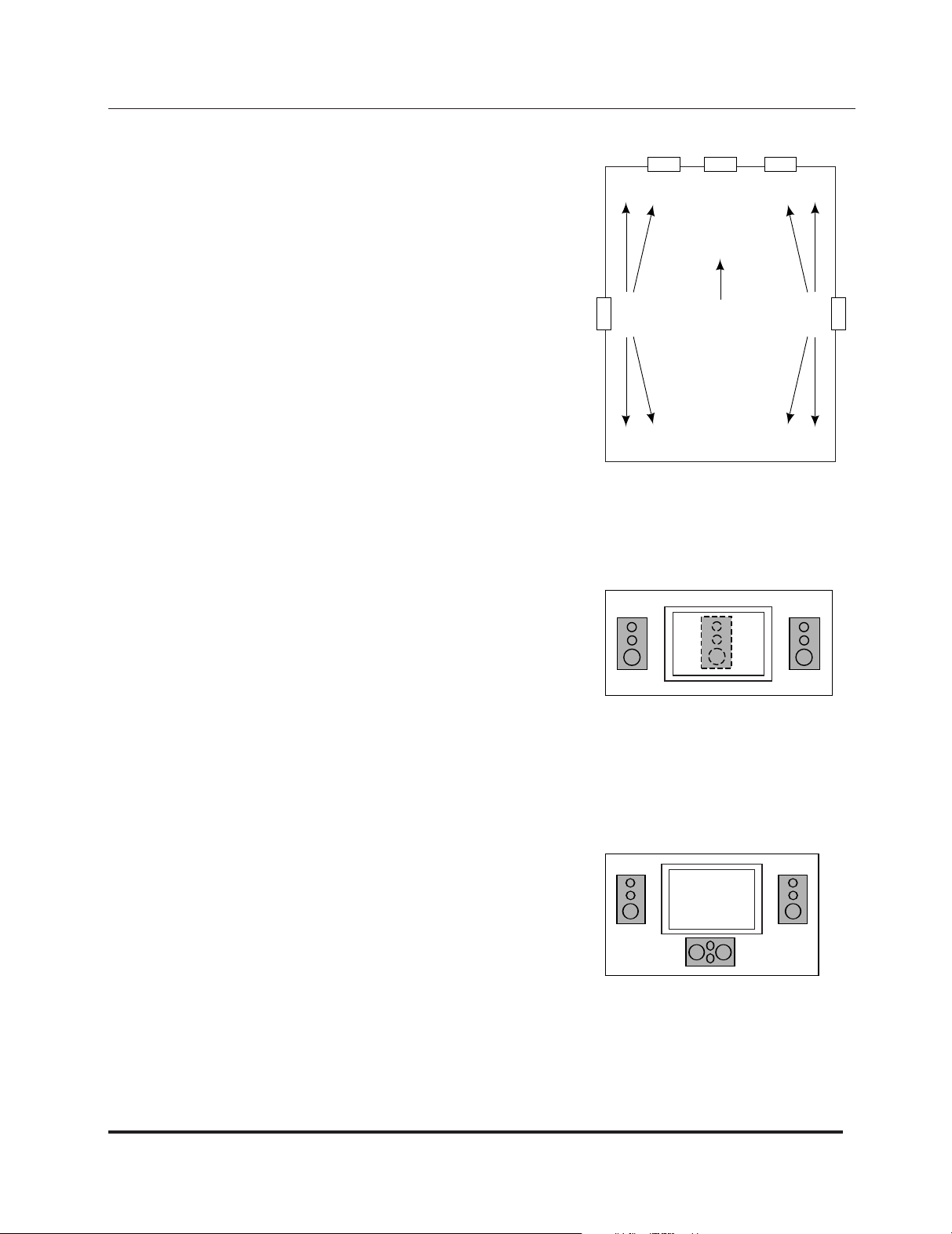
FLOOR PLAN
SPEAKER PLACEMENT
Positioning your loudspeakers properly is critical in order to achieve the
sonic performance of a home theater. Please read the following section
for guidance in correct and optimal placement.
LEFT AND RIGHT SPEAKERS: If you have purchased a Synthesis Three
Array Digital Home Theater System, then the model SAM3VA will serve as
your front left and right main speakers.
Since the left and right speakers have been designed for maximum localization
of sound, they should be placed with the center of the speakers at about the
same height on screen as the actors would be, to aid in the illusion that the
actors’ voices are coming directly from their on-screen images. Ideally, the
speakers will be placed about 45 degrees apart from each other,
from the listening position, so that the distance between the speakers
same as each speaker’s distance from the listener (see Figure 1).
CENTER CHANNEL SPEAKERS
viewed
is the
Figure 1. 5.1-Channel system
SAM3V
SAM3V
installation in order to take advantage of its sound-dispersion characteristics.
If you mount it horizontally, it will not provide the correct dispersion pattern.
If the speaker is being used with a perforated projection screen, it should be
mounted behind the center of the screen (see Figure 2). If a nonperforated
projection screen, plasma display or other fixed video device is being used
in the installation, the preferred center speaker is the model SAM3HA (below).
A:
If you have purchased the vertical channel speaker (model
A) for the center position, be sure to place it vertically during
Figure 2.
SAM3HA: If you have purchased the horizontal channel speaker (model SAM3HA) for the center position, be sure
to position it horizontally during installation in order to take advantage of its
sound-dispersion characteristics. If you mount it vertically, it will not provide
the correct dispersion pattern. Although the preferred speaker model to be
used with a perforated projection screen is the vertical model SAM3VA
(above), the SAM3HA horizontal speaker may be used instead and should be
mounted behind the center of the screen. If a nonperforated projection
screen, plasma display or other fixed video device is being used in the
installation, then the recommended location is directly below and as close
as possible to the video display (see Figure 3), although the inverse of this
method will work also.
Figure 3.
4
Page 5

RCL
FLOOR PLAN
Min. 2'-0"
SPEAKER PLACEMENT
NOTE: I
t is extremely important to place the tweeter/mid-bass arrays for each of the center, left and right speakers
at the same height. The horn array containing the tweeter in the center channel speaker should be no more than two
feet (0.6 meter) higher or lower than those in the left and right speakers. This preserves the “localization integrity” of
“sound pans,”in which the sound appears to move from left to center to right. If the program material also appears to
travel up and down, it can destroy the illusion of panning effects and so should be avoided.
AMBIENT SURROUND SPEAKERS: Although it has been common for many years to use a number of surround
speakers in commercial movie houses, until recently, the traditional home theater configuration called for 5.1
channels, i.e., front left, center, front right, surround left and surround right, plus a low-frequency-effects channel.
The newer surround formats that are appearing in consumer audio equipment are calling for more complicated 6.1and 7.1-channel systems. The advantages of using additional speakers are many. Additional channels enable a more
versatile use of directionality for a more accurate surround presentation. Also, a higher overall sound-pressure level
can be achieved with less energy expenditure from any individual speaker. Placement of the surround speakers
remains critical.
5.1-CHANNEL SYSTEMS
The ambient surround speakers work optimally if they are placed as far back
from the screen as the viewing chairs are. If there are two rows of chairs,
these speakers should be placed between them.
The ambient surround speakers should be placed higher than the seating
area, at least two feet (0.6 meter) above (seated) ear level (see Figure 4).
The preferred method to mount the ambient surrounds is to put them directly in
the side walls. This lets each speaker radiate to the front and back of the room
and to reflect off the side walls.
There are a few instances in which the ambient surrounds would perform
better if mounted in the ceiling rather than the walls. If one or both of the walls
due to the presence of windows, fabric, furniture or
”
are “acoustically dead
,
other absorption, it may be necessary to turn the ambient speakers sideways
and, instead of mounting them in a vertical orientation, mount them in the
ceiling in a horizontal orientation.
6.1-CHANNEL SYSTEMS
A 6.1-channel system can be thought of as a 5.1-channel system with the
addition of a rear center speaker placed midway between the two surround
speakers, and further to the rear than the surrounds. It should be placed at the
same height as the side surround speakers (see Figure 5).
Figure 4.
Figure 5. 6.1-Channel system
5
Page 6

RCL
SIDE
LEFT
SIDE
RIGHT
R
EAR LEFT
R
EAR RIGHT
SPEAKER PLACEMENT
7.1-CHANNEL SYSTEMS
In a 7.1-channel system, two speakers are added for rear fill, in addition to the surround speakers in a 5.1-channel system. The two additional speakers are placed on
the rear wall or near the rear wall in the ceiling (see Figure 6).
Figure 6. 7.1-Channel system
CONNECTING THE SPEAKERS TO THE REST OF YOUR SYSTEM
To connect the Synthesis Three Array loudspeakers to the power amplifiers or receiver, use two-conductor insulated
speaker wire. We recommend #14 AWG wire as a minimum size. Your JBL dealer can recommend suitable cables.
Both the SAM3VA and SAM3HA utilize 5-way binding posts that can accommodate up to #10 AWG stranded wire.
PREPARING THE HOOKUP WIRE
1. First determine the distance between your amplifier and the most distant speaker in each group (fronts, surrounds,
back surrounds, subwoofers).
2.
Now make the hookup wires for all speakers in each group this length, even if one speaker is much closer
amplifier than the other. This will help maintain proper signal balance.
3. Strip off 3/8" (10mm) of insulation from both ends of each conductor.
Twist each set of standard wires into a tightly bunched spiral.
4.
Speakers and electronics terminals have corresponding (+) and (–) terminals. Most manufacturers of speakers and
5.
electronics, including JBL, use red to denote the (+) terminal and black for the (–) terminal, although some electronics manufacturers have adopted the new color-coding standard promulgated by the Consumer Electronics
Association. In that case, the positive terminal will be colored to correspond to the channel position, while the
negative terminal will be black.
It is important to connect all speakers identically: (+) on the speaker to (+) on the amplifier and (–) on the speaker to
(–) on the amplifier. Wiring “out of phase” results in thin sound, weak bass and poor imaging.
With the advent of multichannel surround sound systems, connecting all of the speakers in your system with the cor
rect polarity remains equally important to preserve the proper ambience and directionality of the program material.
Now find a visual difference between the two conductors of each molded pair of speaker wires. Differentiating
marks can be a different color wire (copper or silver); a strand of yarn in one conductor; thin, raised ribs on one part
of the outer insulation; or a printed marking on one part of the outer insulation. It doesn’t matter which of the two
strands go to the (+) and (–) on the speakers and amplifiers, as long as all speakers are connected identically. Push
down on the binding post, insert the wire into the hole, and release.
to your
-
6
Page 7

Front
Left
To
Subwoofers
Front
Right
Front
Center
Side
Left
Side
Right
Rear
Left
Rear
Right
S7150
WARNING:
serial number
ATTENTION:
VOIR LECAHIER D'
INSTRUCTION
15A
120V
50/60Hz
1800W
Ch. 1 Output
ON
OFF
MANUALONAUTO
ON
IN
O
UT
SPKR-1 SPKR-2
:SIVA
R
IR
VUOSAPEN
E
UQIR
T
CE
L
E
C
OHC
E
DE
U
QSI
R
N
OITU
AC
KC
OHSCIRTCELEF
O
K
SI
R
NEPOT
ONO
D
~
DESIGNED, ENGINEERED ANDMANUFACTURED
IN THE UNITED STATES OF AMERICA
S
5160 POWER AMPLIFIER
JBL SYNTHESIS
NORTHRIDGE, CA
TRIGGERS
+
-
Ch. 2 Output
+
-
Ch. 3 Output
+
-
Ch. 4 Output
+
-
Ch. 5 Output
+
-
Ch. 6 Output
+
-
Ch. 7 Output
+
-
WARNING:
To reduce the risk of fire or electric shock, do not expose this appliance to rain or moisture
HAZARDOUS ENERGY, MAKE PROPER SPEAKER CONNECTIONS; SEEOWNERS MANUAL BEFORE USING.
N
O USER SERVICEABLE PARTSINSIDE. REFER
SERVICING TO QUALIFIED PERSONNEL
SDP-5
Ch. 1
Input
Ch. 2
Input
Ch. 3
Input
Ch. 4
Input
Ch. 5
Input
Ch. 6
Input
Ch. 7
Input
SDEC-3000
S
/PDIFINPUTS
IRIN
T
RIGGER
OUTPUTS
O
UT
S
/PDIF
S/N
R
S-232
2
1
VIDEO
S-VIDEOAUDIO
INPUTS
(
L)
(R)
(C)
(SUB)
(LS)
(RS)
L
R
(L)
(R)
(C)
(SUB)
(LS)
(RS)
Y
P
RPB
Y
PR PB
Y
PR PB
I
NPUT 1
I
NPUT 3
INPUT 2
Y
PR PB
OUTPUT
1
2
3
4
1
21 2
3
4
12345
1
2345678
CENTER
F
RONT
S
IDE
REAR
L
R
L
R
SUBWOOFER
MAIN
VIDEO
ZONE2
VIDEO
A
UDIO
1
SDP-5 Digital Surround Processor/Controller
JBL, Inc. Northridge, CA
Assembledin USA
A
C100-240V ~ 50-60 HZ, 60W
OUTPUTS
2
T
UV
US
C
RISK OF ELECTRICSHOCK
DONOT OPEN
ATTENTION
RISQUE DE CHOC
ELECTRIQUE
NEPAS OUVRIR
CAUTION
CONNECTING THE SPEAKERS TO THE REST OF YOUR SYSTEM
Figure 7. Synthesis Three Array with powered subwoofers
NOTE: Although the
SDP-5 is shown here,
connections for the
SDP-40 are similar.
INPUT CHANNEL OUTPUT
1 Left Front C
A
ight Front C2
A2 R
A3 Center C3
A4 Left Side C4
B1 Right Side D1
B2 Left Rear D2
B3 Right Rear D3
B4 Subwoofer D4
1
INPUT
Ch. 1
Left Front
Ch. 2 Right Front
Ch. 3 Center
Ch. 4 Left Side
Ch. 5 Right Side
7
Ch. 6 Left Rear
Ch. 7 Right Rear
Page 8

To Left
Sub
To Right
Sub
S800
1
0A
120V
50/60Hz
1200W
ON
OFF
M
ANUAL
O
N
A
UTO
ON
IN
OUT
Ch. 2 Output
Ch. 1
BRIDGED
Input
Ch. 2
Input
ATTENTION:
VOIR LECAHIER D'
INSTRUCTION
WARNING:
HAZARDOUSENERGY, MAKE PROPER SPEAKER CONNECTIONS; SEE OWNERS MANUAL BEFORE USING.
serial number
STEREOMONO
BRIDGED
Ch. 1 Output
B
RIDGED
+
-
+-+
-
DESIGNED, ENGINEERED AND MANUFACTURED
I
NTHE UNITED STATES OF AMERICA
S800 POWER AMPLIFIER
JBL SYNTHESIS
NORTHRIDGE,CA
TRIGGERS
AVIS:
RISQUE DE CHOC ELECTRIQUE NE PASOUVRIR
C
AUTION
RISK OF ELECTRIC SHOCK
D
ONOT OPEN
~
No user serviceable parts inside. Refer
servicing toqualified personnel.
WARNING;WARNING;
To reduce the risk of fire or
electric shock, do notexpose
this appliance to rain or moisture
S7150
WARNING:
serial number
ATTENTION:
VOIR LECAHIER D'
INSTRUCTION
15A
1
20V
50/60Hz
1800W
Ch. 1 Output
ON
OFF
M
ANUAL
O
N
A
UTO
O
N
I
N
OUT
S
PKR-1 SPKR-2
:SIVA
R
IR
VUOSAPEN
E
UQIR
T
CE
L
E
C
OHC
E
DE
U
QSI
R
N
OITU
AC
KC
OHSCIRTCELEF
O
K
SI
R
NEPOT
ONO
D
~
D
ESIGNED,ENGINEERED AND MANUFACTURED
I
NTHE UNITED STATES OF AMERICA
S5160 POWER AMPLIFIER
JBL SYNTHESIS
N
ORTHRIDGE, CA
TRIGGERS
+
-
Ch. 2 Output
+
-
Ch. 3 Output
+
-
Ch. 4 Output
+
-
Ch. 5 Output
+
-
Ch. 6 Output
+
-
Ch. 7 Output
+
-
WARNING:
To reduce the risk of fire orelectric shock, do not expose this appliance to rain or moisture
HAZARDOUSENERGY, MAKE PROPER SPEAKER CONNECTIONS; SEE OWNERS MANUAL BEFORE USING.
NO USER SERVICEABLEPA RTS INSIDE. REFER
S
ERVICING TO QUALIFIED PERSONNEL
S
DP-5
C
h. 1
I
nput
C
h. 2
I
nput
C
h. 3
I
nput
C
h. 4
I
nput
C
h. 5
I
nput
C
h. 6
I
nput
C
h. 7
I
nput
SDEC-3000
S/PDIFINPUTS
IRIN
TRIGGER
O
UTPUTS
OUT
S/PDIF
S
/N
RS-232
2
1
VIDEO
S-VIDEOAUDIO
I
NPUTS
(
L)
(R)
(C)
(SUB)
(
LS)
(
RS)
L
R
(
L)
(R)
(C)
(SUB)
(LS)
(RS)
Y
PR PB
Y
PR PB
Y
PR PB
I
NPUT 1
INPUT 3
INPUT 2
Y
P
RPB
OUTPUT
1
2
3
4
1
21 2
3
4
1
2
3
4
5
12345678
C
ENTER
F
RONT
SIDE REAR
L
R
L
R
SUBWOOFER
MAIN
VIDEO
Z
ONE2
VIDEO
AUDIO
1
S
DP-5 Digital Surround Processor/Controller
J
BL, Inc. Northridge, CA
Assembledin USA
AC100-240V ~ 50-60 HZ, 60W
OUTPUTS
2
TUV
US
C
RISK OF ELECTRICSHOCK
D
ONOT OPEN
A
TTENTION
RISQUE DE CHOC
ELECTRIQUE
NEPAS OUVRIR
CAUTION
CONNECTING THE SPEAKERS TO THE REST OF YOUR SYSTEM
Figure 8. Synthesis Three Array with passive subwoofers
NOTE: Although the SDP-5
is shown here, connections
for the SDP-40 are similar.
INPUT CHANNEL OUTPUT
A1 Left Front C1
2 Right Front C2
A
3 Center C3
A
Left Side C4
A4
1 Right Side D1
B
2 Left Rear D2
B
3 Right Rear D3
B
B4 Subwoofer D4
INPUT
Ch. 1 Left Front
Ch. 2 Right Front
Ch. 3 Center
Ch. 4 Left Side
Ch. 5 Right Side
Ch. 6 Left Rear
Right Rear
Ch. 7
Ch. 1 Left Sub
Ch. 2 Right Sub
8
Page 9

TROUBLESHOOTING
SY
MPTOM
PR
OBABLECAUSE
SO
LUTION
No sound coming • Amplifier not turned on •Turn on amplifier.
from speaker
• Amplifier gain is low •Make sure that there is
amplifier gain for that channel.
• Correct source not •Select proper source.
selected or turned on
• Defective patch cords to amplifier •Check/replace patch cords.
• Speaker wires not • Check speaker wire
connected to amplifier connection to amplifier.
• Balance control set improperly •Make sure Balance control is set
at center, or 12 o’clock, position.
• Speaker wires damaged •Make sure none of the speaker wires
or shorted are frayed, cut or punctured. Make sure
no wires are touching other wires or
terminals and creating a short circuit.
®
• Speaker not configured •In Dolby
Digital or DTS®mode, make
correctly sure that the receiver/processor is
configured so that the speaker in
question is enabled.
Bass is very weak •
®
• Center speaker is configured •In Dolby Pro Logic
mode, make sure the
incorrectly center speaker is not in phantom mode.
• Problem not diagnosed •To diagnose the likely source of the
problem, it is often helpful to switch the
nonfunctioning speaker with one that
is functioning correctly. Turn off all
electronics before exchanging the
speakers. Turn everything back on, and
determine whether the problem is in
the same place, or has moved with the
speaker. If the problem is in the same
place, the source is most likely with your
receiver or amplifier. If the problem has
followed the speaker, then contact your
authorized JBL Synthesis custom installer
or dealer for further assistance. If that
is not possible, visit our Web site at
www.jblsynthesis.com for further information.
Make sure that positive terminals on the
Subwoofers are wired out
of phase
•
subwoofers go to the positive terminals
on the amplifiers (red) and do the same
for the negatives.
Subwoofers have not •Experiment with different locations.
•
been placed optimally
9
Page 10

SPECIFICATIONS
SAM3HA SAM3VA
U
L
-FR
TRAHIGH
HIGH-FR
LOW-FR
EQUENCYDRIVER
EQUENCYTRANSDUCER
EQUENCYTRANSDUCER
SENSITIVITY (2.83V/1M)
FREQUENCY RESPONSE (–3DB) 48HZTO40KHZ 48HZTO40KHZ
MA
XIMUMRECOMMENDED
AMPLIFIER POWER
CR
OSSOVERFREQUENCIES
NO
MINALIMPEDANCE
DI
MENSIONS
(H X W X D) 9-5/8" X 28-5/8" X 9-1/16"* 27-3/8" X 10-3/16" X 12-5/8"*
WEIGHT PER SPEAKER 31 LB (14KG) 34 LB (15.5KG)
045TI 1" (25MM) PURE-T
D
RIVER WITH ALUMINUM EDGE
2" (51MM) N
A
ND
MOUNTED IN A CONSTANT-DIRECTIVITY HORN MOUNTED IN A CONSTANT-DIRECTIVITY HORN
175ND-3 1-3/4" (44MM) AQ
-D
A
LUMINUM
A
LUMINUM EDGE
MOTOR ASSEMBLY, MOUNTED IN A VERTICAL MOTOR ASSEMBLY, MOUNTED IN A VERTICAL
C
ONSTANT-DIRECTIVITY HORN CONSTANT-DIRECTIVITY HORN
OME COMPRESSION DRIVER WITH ALUMINUM-DOME COMPRESSION DRIVER WITH
6-1/2" (165MM) DEEP-A
MATERIAL WITH DUAL
, S
M
AGNETS
HIELDED
ITANIUM COMPRESSION
-W
OUND VOICE COIL DRIVER WITH ALUMINUM EDGE-WOUND VOICE COIL
EODYMIUM MOTOR ASSEMBLY
UAPLAS-TREATED
-W
OUND VOICE COIL AND NEODYMIUM ALUMINUM EDGE-WOUND VOICE COIL AND NEODYMIUM
NODIZED CONE AND DOME
, AND2" (51MM) N
“INSIDE” NEODYMIUM MATERIAL WITH DUAL “INSIDE” NEODYMIUM
MOTOR STRUCTURE AND
2" M
045TI 1" (25MM) PURE-T
175ND-3 1-3/4" (44MM) AQ
6-1/2" (165MM) DEEP-A
, S
AGNETS
(51MM) VOICE COILS (51MM) VOICE COILS
89
DB
200 WA
TTS
89
DB
200 WA
TTS
1KHZ, 10KHZ 1KHZ, 10KHZ
6 OH
(244M
MS
X 727MMX 230M
M
) (695M
M
6 OH
MS
M
X 259MMX 321M
ITANIUM COMPRESSION
EODYMIUM MOTOR ASSEMBLY
UAPLAS-TREATED
NODIZED CONE AND DOME
MOTOR STRUCTURE AND
HIELDED
)
M
,
2"
* Note: Dimensions do not include mounting hardware or feet. Add 1" (25mm) height for feet.
All features and specifications are subject to change without notice.
JBL, JBL Synthesis and Synthesis are trademarks of Harman International Industries, Incorporated, registered in the United States and/or other countries.
Array, Symmetrical Field Geometry and Vented Gap Cooling are trademarks of Harman International Industries, Incorporated.
THX is a registered trademark, and THX
SACD is a trademark of Sony Corporation.
Dolby and Pro Logic are registered trademarks of Dolby Laboratories.
DTS is a registered trademark of DTS, Inc.
Ultra2 is a trademark, of THX Ltd. All rights reserved.
10
Page 11

NOTES
11
Page 12

Harman Consumer Group, Inc.
250 Crossways Park Drive
Woodbury, NY 11797
8500 Balboa Boulevard
Northridge, CA 91329
818.830.8757
www.jblsynthesis.com
Part No. 301227-001 9/06
Declaration of Conformity
We, Harman Consumer Group International
2, route de Tours
72500 Château du Loir
France
declare in own responsibility that the products described
in this owner’s manual are in compliance with technical
standards:
EN 61000-6-3:2001
EN 61000-6-1:2001
Luc Guillaume
Harman Consumer Group International
Château du Loir, France 9/06
 Loading...