

Page 1

®
SYNTHESIS
S5160
POWER
AMPLIFIER
USER’S
MANUAL
Page 2

®
Page 3

TABLE OF CONTENTS
A Harman International Company
1.0 Precautions _______________________________________________________4
1.1 Important Safeguards for Audio Products ________________________________4
2.0 Introduction and Features ____________________________________________6
2.1 Included __________________________________________________________7
3.0 S5160 Operation and Controls _________________________________________8
4.0 Connecting Your JBL Synthesis System_________________________________11
4.1 JBL Synthesis One: Suggested Rack-Mounting Order ______________________11
4.2 JBL Synthesis One: Control Wiring Diagram _____________________________12
4.3 JBL Synthesis One: Interconnection Diagram ____________________________13
5.0 Physical Considerations _____________________________________________14
6.0 Troubleshooting ___________________________________________________15
7.0 Specifications _____________________________________________________16
JBL Synthesis S5160 Power Amplifier User’s Manual
© 2005 Harman International Industries, Incorporated. All rights reserved.
JBL and JBL Synthesis are registered trademarks of Harman International Industries, Incorporated.
THX and THX Ultra are trademarks of THX Ltd., which may be registered in some jurisdictions. All rights reserved.
®
JBL Consumer Products
8500 Balboa Boulevard, Northridge, CA 91329
250 Crossways Park Drive, Woodbury, NY 11797
516.255.4JBL
Part Number: S5160/120OM
3
Page 4
PRECAUTIONS
1.0
1.1 Important Safeguards
For Audio Products
PLEASE READ CAREFULLY ALL THE
FOLLOWING IMPORTANT SAFEGUARDS
THAT ARE APPLICABLE TO YOUR EQUIPMENT
1. Read these instructions.
2. Keep these instructions.
3. Heed all warnings.
4. Follow all instructions.
5. Do not use this apparatus near water.
6. Clean only with a dry cloth.
7. Do not block any ventilation openings. Install in accor-
dance with the manufacturer’s instructions.
8. Do not install near any heat sources such as radiators,
heat registers, stoves or other apparatus (including amplifiers) that produce heat.
9. Do not defeat the safety purpose of the polarized or
grounding-type plug. A polarized plug has two blades with
one wider than the other. A grounding-type plug has two
blades and a third grounding prong. The wide blade or the
third prong are provided for your safety. If the provided plug
does not fit into your outlet, consult an electrician for
replacement of the obsolete outlet.
10. Protect the power cord from being walked on or
pinched, particularly at plugs, convenience receptacles and
the point where they exit from the apparatus.
11. Only use attachments/accessories specified by the
manufacturer.
12. Use only with the cart, stand, tripod,
bracket or table specified by the manufacturer
or sold with the apparatus. When a cart is
used, use caution when moving the cart/apparatus
combination to avoid injury from tip-over.
13. Unplug this apparatus during lightning storms or when
unused for long periods of time.
14. Refer all servicing to qualified service personnel.
Servicing is required when the apparatus has been damaged in any way, such as power-supply cord or plug is
damaged, liquid has been spilled or objects have fallen into
the apparatus, the apparatus has been exposed to rain or
moisture, does not operate normally, or has been dropped.
15. Do not use attachments not recommended by the
product manufacturer, as they may cause hazards.
16. This product should be operated only from the type
of power source indicated on the marking label. If you are
not sure of the type of power supply to your home, consult
your product dealer or local power company. For products
intended to operate from battery power, or other sources,
refer to the operating instructions.
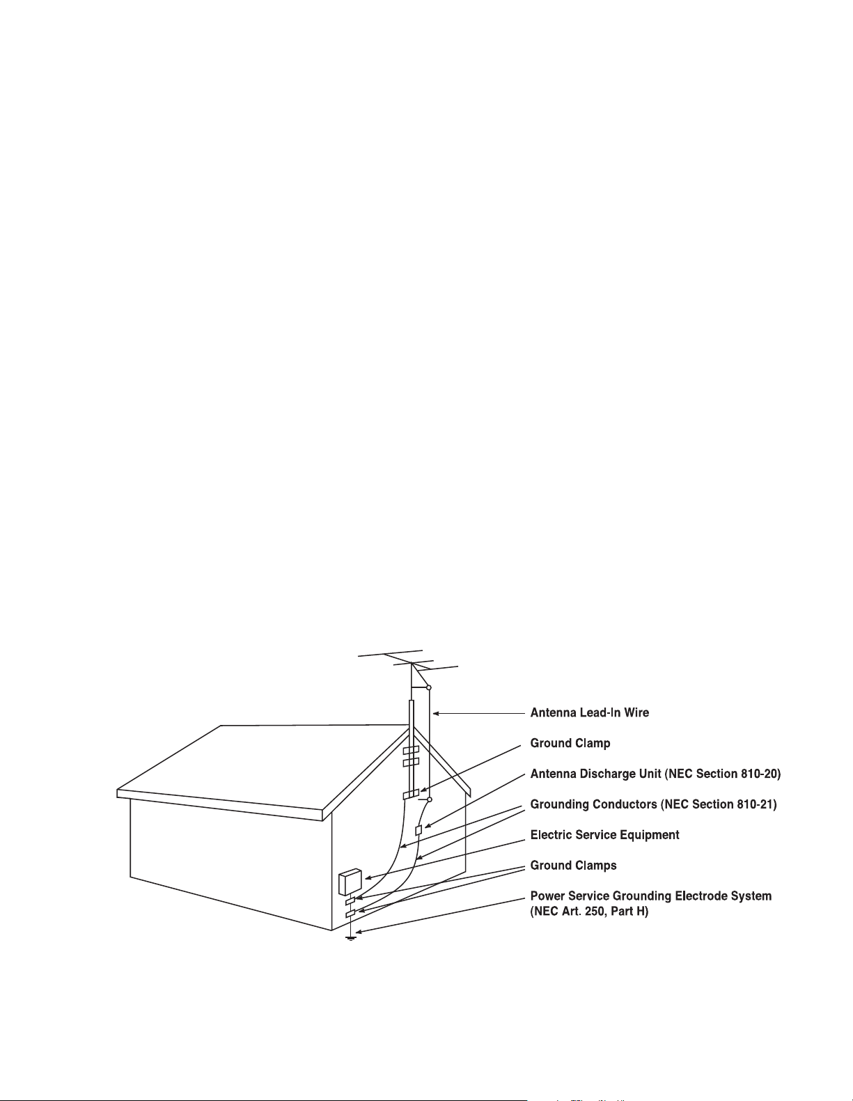
17. If an outside antenna or cable system is connected
to the product, be sure the antenna or cable system is
grounded so as to provide some protection against voltage
surges and built-up static charges. Article 810 of the
National Electrical Code, ANSI/NFPA 70, provides information with regard to proper grounding of the mast and supporting structure, grounding of the lead-in wire to an antenna discharge unit, size of grounding conductors, location
of antenna-discharge unit, connection to grounding electrodes, and requirements for the grounding electrode.
See Figure A.
4
Page 5
PRECAUTIONS
1.0
18. An outside antenna system should not be located in
the vicinity of overhead power lines or other electric light
or power circuits, or where it can fall into such power lines
or circuits. When installing an outside antenna system,
extreme care should be taken to keep from touching such
power lines or circuits, as contact with them might be fatal.
19. Do not overload wall outlets, extension cords, or integral convenience receptacles, as this can result in a risk
of fire or electric shock.
20. Never push objects of any kind into this product
through openings, as they may touch dangerous voltage
points or short-out parts that could result in a fire or electric shock. Never spill liquid of any kind on the product.
21. The apparatus shall not be exposed to dripping or
splashing, and no objects filled with liquids, such as vases,
shall be placed on the apparatus.
22. Do not attempt to service this product yourself, as
opening or removing covers may expose you to dangerous voltage or other hazards. Refer all servicing to qualified
service personnel.
23. When replacement parts are required, be sure the
service technician has used replacement parts specified by
the manufacturer or that have the same characteristics as
the original part. Unauthorized substitutions may result in
fire, electric shock or other hazards.
24. Upon completion of any service or repairs to this
product, ask the service technician to perform safety
checks to determine that the product is in proper operating condition.
25. The product should be mounted to a wall or ceiling
only as recommended by the manufacturer.
Note to CATV system installer:
This reminder is provided to call the CATV system
installer’s attention to Article 820-22 of the NEC that provides guidelines for proper grounding and, in particular,
specifies that the cable ground shall be connected to the
grounding system of the building, as close to the point of
cable entry as practical.
Figure A.
Example of Antenna Grounding as per
National Electrical Code ANSI/NFPA 70
Part No. HCGUL1492/6500 04/2004 EN
5
Page 6

INTRODUCTION
AND FEATURES
2.0
Introduction
Congratulations on your purchase of this JBL Synthesis
S5160 power amplifier! You have chosen a product that
embodies the best of what JBL has discovered about the
emotional power of audio reproduction in more than fifty
years of preeminence in the field. This amplifier has been
designed and crafted to provide the user with a high level
of sonic performance; special attention has been paid to
minimize the number of components in the audio signal
path, resulting in extremely low distortion, excellent transient response and wide dynamic range. Synthesis products set new benchmarks in audio technology, and, when
used as part of a complete JBL Synthesis system, will
bring the ambience and acoustics of some of the world’s
greatest concert halls and theaters into your home.
To obtain the best performance from this amplifier, please be
sure to completely read this user’s manual and use the
S5160 only in accordance with its instructions.
Features
The JBL Synthesis S5160 power amplifier features the
following:
THX Ultra
This amplifier meets or exceeds the stringent specifications, including those for power handling, total harmonic distortion, frequency
response, signal-to-noise ratio, slew rate, and crosstalk, set by the
THX Ltd. Audio division in their specifications for “Ultra”-class certification. When incorporated into a complete THX
hear in your home what the director and sound engineer heard in
the recording studio.
Full Five-Channel Operation
The S5160 has been designed to integrate well into the
world of multichannel audio. It is designed to reproduce
the front left and right, center and side channels, to produce a truly enveloping sound field. When coupled with
a high-quality subwoofer amplifier, such as the S800, it is
a solid foundation on which to build a high-performance
home cinema system that will astound the listener with its
power and realism. The S5160 is specially designed for
use with a Synthesis One system in which the front left,
right and center speakers are bi-amplified for smoother
and more accurate reproduction of every nuance of a
movie soundtrack or musical selection. Two S5160
™
Specifications
®
system, you will
amplifiers may be used, in conjunction with two S800
subwoofer amplifiers, to power a complete 7.1-channel
home theater system. Alternatively, a single S5160 may
be used with one S800 subwoofer amplifier to power a
5.1-channel system.
High Power Capability
The S5160 provides a satisfying 160 watts per channel of
distortion-free audio (<0.03% THD) into 8 ohms. Because
of their power capabilities, all Synthesis amplifiers have an
extremely wide dynamic range, an element critical to realistic
home cinema. Sound levels equal to those at original performances are easily re-created in even the largest of home
listening environments.
Auto Turn-On and Power Sequencing Circuitry
When used in a JBL Synthesis system, the S5160 can be
turned on automatically whenever the surround processor
is activated. No longer do you have to get out of that chair
to turn on the various pieces of equipment in your entertainment system; just one touch on the remote control of
the surround processor, and you’re a few seconds away
from a truly impressive audio presentation!
Modern amplifiers produce more power per channel (and
frequently have more channels) than those of the traditional
two-channel stereo era. Due to the high current demands
of power amplifiers at the instant of turn-on, the S5160,
S7150 and S800 amplifiers and the SDEC digital equalizer are equipped with power sequencing circuits that turn
on each unit in sequence, avoiding the large instantaneous
current demand (and possible house circuit breaker tripping) that would occur should they all turn on at the same
instant.
6
Page 7

INTRODUCTION
AND FEATURES
2.0
Quiet Cooling
The S5160 utilizes a fan to cool the amplifier channels,
ensuring long-term reliability. To reduce fan noise to an
absolute minimum, a thermal sensing and control circuit
that senses increases
and powers a fan at a speed proportional to that temperature increase
the S5160 is used at lower volume levels, the fan turns
very slowly – and quietly. At high listening levels (and the
higher operating temperatures this creates within any
amplifier), the sensing circuitry causes the fan to turn
faster, producing increased cooling. As a result, the fan
is never turning faster than necessary, and most of the
noise that is generated is masked by the program being
listened to.
Comprehensive and Isolated Circuit Protection
The S5160 amplifier employs sophisticated protection circuitry (one for each channel) that senses many possible fault
conditions, such as shorted loudspeaker wires or excess
power demand, and turns the affected channel(s) and their
blue front-panel indicators off until the fault condition is
removed, at which time normal operation is automatically
restored. While protection of this sort is not uncommon in
today’s well-designed amplifiers, a remarkable feature of
the S5160’s protection circuitry is that it is optically coupled to the signal circuit; there is no direct electrical connection between the signal path and the protection circuitry.
As a result, there can be no coloration of the
music, no interaction between protection and
amplification, until certain thresholds are
exceeded, at which point the channel(s) turn
off completely.
in temperature within the amplifier
has been incorporated in the S5160
. When
2.1 Included
Each S5160 amplifier includes the following items packed
in the carton. If any of these items is missing, please contact your JBL Synthesis dealer or distributor, or visit our
Web site at www.jblsynthesis.com.
One (1) detachable power cord
One (1) 6-foot 5-pin DIN trigger cable (M/M)
Two (2) 5-pin DIN/2-pin bare wire adapters
Two (2) 2-pin bare wire plugs
Owner’s manual
7
Page 8

®
S5160 OPERATION AND
CONTROLS
3.0
1. Power Switch
Pushing this button is all that is required to turn on the
S5160 if it is not part of a Synthesis system and the
Manual On/Auto On switch
Manual On position. If the amplifier is used as part of a
JBL Synthesis system, and the Manual On/Auto On
switch
¶
is in the Auto On position, the amplifier will
turn on when the surround processor is activated. In this
application, the front-panel pushbutton Power switch
should be left in the ON (in) position. See the description
of the Manual On/Auto On switch
mation on turning on the S5160.
2. Standby Indicator
This indicator, immediately above the front-panel Power
switch, will glow red when the amplifier is in the “standby”
mode, whether operating as part of a Synthesis system
or not. When the S5160 is in the “on” mode, this light will
shut off and the blue “on” mode indicators will light.
3. Power Indicators (Blue)
These indicators will light up when the power amplifier
is in the “on” mode. Each monitors the operation of one
channel, and will be extinguished if that channel’s
protection circuitry is activated.
¶
(rear panel) is in the
¶
for more infor-
4. Input Jacks (Ch.1 Through Ch.5)
The output signals from the Synthesis digital processor and
equalizer are connected to the input jacks in a Synthesis
One system. We suggest that the channels be assigned
as follows:
Amplifier #1:
Channel 1 Center Low-Frequency
Channel 2 Center High-Frequency
Channel 3 Right Front Low-Frequency
Channel 4 Right Front High-Frequency
Channel 5 Right Rear Surround
Amplifier #2:
Channel 1 Right Side Surround
Channel 2 Left Side Surround
Channel 3 Left Front Low-Frequency
Channel 4 Left Front High-Frequency
Channel 5 Left Rear Surround
8
Page 9

¢
∞
S5160 OPERATION AND
CONTROLS
3.0
ª
•
¶
§
‚
5. Speaker Terminals
Connect the speakers to these terminals, following the normal convention: Wire the “+” side of the speaker to the red
terminal, and the “–” side to the black terminal. Wire the
speakers with the proper polarity; reversing any speaker’s
connections will not damage either the speaker or the
amplifier, but will result in poor low-frequency performance
and imprecise imaging.
WARNING: Terminals marked with the flash symbol
are hazardous when live. External wiring connected
to those terminals requires installation by trained
personnel, and the use of ready-made lead cords.
NOTE: The minimum load impedance that this amplifier
can handle safely is 8 ohms per channel. Using lower
impedance loads can damage the unit and will void
your warranty!
Wire Run Length Rec. Ga.
Wire-Run Length Minimum Gauge
Up to 20' 16
Up to 50' 14
Up to 100' 12
6. External Fuses
AC mains fuses are located on the back panel of the
amplifier. These fuses will not blow unless the amplifier is
asked to produce more power than its design allows for
a prolonged period or to prevent excessive current draw,
which could damage internal components during a fault
condition.
The amplifier has been designed to operate under virtually
all conditions. Even momentary short-circuiting of the
output (speaker) connections will not ordinarily damage
the output circuitry (although it will activate internal protection circuitry and cause one or more of the front-panel
LED indicators to be extinguished until the circuit resets
automatically).
Fuse Replacement
To remove the fuse, turn off the Power switch and disconnect the power plug from the AC mains. Unscrew the fuse
holder cap and remove the fuse; install the new fuse and
secure the holder cap; and reconnect the AC mains. If
after replacing the fuse the unit is inoperative, service is
required; contact your JBL Synthesis dealer.
WARNING: Always unplug the amplifier from
the AC mains before removing any fuse.
IMPORTANT: Never install a fuse that has a
higher rating than that specified on the back
panel of the amplifier or in the owner’s
manual.
9
Page 10

S5160 OPERATION AND
CONTROLS
3.0
7. Manual On/Auto On Switch
Put this switch in the Auto On position if the amplifier is
being used as part of a JBL Synthesis system. When used
in this way, the S5160 will automatically turn on when the
Power switch is depressed and the surround processor is
activated. For other installations, or should individual control
of each component be desired, put this switch in the
Manual On position. The amplifier will then be controlled
solely by the front-panel switch.
8. In/Out DIN Jacks
If you are using the amplifier as part of a JBL Synthesis
system, it is necessary to use these jacks to interconnect to
other system components so that control signals (Power
On/Off and Music/Cinema mode switching) can be transmitted from one unit to the next, starting at the surround
processor, through the equalizer and amplifiers, and ending
at the speakers. Follow the connection diagrams on the
following pages for detailed information regarding these
connections. Make connections to these jacks only as
shown in the diagrams. If these jacks are used in any other
manner, e.g., to control electric screens, the unit can be
damaged and the warranty will be void. For specific electrical
information on these jacks, contact JBL Synthesis
Customer Service at 516.255.4JBL.
Do not plug anything into these jacks if you
are not using the S5160 with a JBL Synthesis
system.
9. Speaker Mode Control Connectors
The front left and front right speakers are switched
between Music and Cinema modes by signals present
at both the DIN connectors (as described in Section 8)
AND the two-conductor connectors shown at
The installer may find it preferable to use two-conductor
wire (18-gauge recommended) rather than long multiconductor DIN cables for the mode-switching connection
between the S5160 and these two speakers. Adaptors
supplied with the S5160 are used at the speaker end of
the wire to allow connection to the speakers’ DIN input
connectors. Proper polarity must be observed, as shown in
the wiring diagrams; reverse the connections at one end of
the wire if the speaker(s) do not switch modes – from
horn (Cinema) to tweeter (Music).
Note that five-conductor DIN cables MUST be used
between all other components to allow correct power and
mode switching, and that the same warning not to plug
anything into these jacks if you are not using the S5160
with a JBL Synthesis system applies here; do not attempt
to use these jacks to control anything other than the
mode-switching function of JBL Synthesis speakers, as
this may damage the S5160 and will void the warranty.
10. AC Inlet
Your S5160 is shipped with an IEC-type removable power
cord that mates with the AC inlet on the rear panel. To
ensure proper operation, use the supplied power cord.
This amplifier is NOT a multivoltage unit; using a
power cord that is not compatible with a 120V, 60Hz AC
wall receptacle will void the warranty.
ª
.
10
Page 11

CONNECTING YOUR
SDP-40
SDEC-1000A
S800
S5160
Top
#1
#2
#3
#4
JBL SYNTHESIS SYSTEM
4.0
General Information
A Synthesis One installation utilizing the benefits of biamplification of the front speakers incorporates a total
of four power amplifiers; two S5160’s, and two S800’s.
Eight of the 10 channels on the S5160’s are to be used
for driving the high-frequency and low-frequency inputs on
the left, center and right speakers, as well as the two side
ambient speakers, as indicated in the chart on page 8.
Please also refer to the connection diagram on page 14.
Use the simplified connection diagrams on the following
pages to help you understand how to connect the S5160
amplifier to a JBL Synthesis system. These diagrams are
intended to show the signal flow through the system. For
more detail in making these connections, please refer to
the JBL Synthesis Certified Dealer Installation Manual.
Connect DIN and audio cables between system components, as
shown on the following pages. Make sure that on all power
amplifiers the Power switches are in the depressed (ON)
position and that the Manual On/Auto On switches
are in the Auto On position. Operated in this mode, all of
the components will turn on with one touch of the Power
switch on the surround processor’s remote control.
¶
4.1 JBL SYNTHESIS ONE:
SUGGESTED RACK-MOUNTING
ORDER
11
Page 12

WARNING
– To reduce the risk of
fire or electric shock, do not expose
this appliance to rain or moisture.
Do not remove cover. No user
serviceable parts inside. Refer
servicing to qualified service personnel.
THX® IS A REGISTERED
TRADEMARK OF
LUCASFILM, LTD.
SDEC-1000A
Digital Equalizer Controller
JBL Inc., Northridge CA
Made in USA
R-AMB L-AMB R-SUB L-SUB C-HI R-HI L-HI R-IN L-IN SUB-IN C-IN
ANALOG INPUT
R-AMB-IN L-AMB-IN
THX
®
CONNECTOR
OUTPUT
MANUAL
ON
RS-232
DIN IN
DIN OUT
AUTOONAUTO
MODE
CINEMA
MODE
R-LO L-LO
C-LO
SDEC-1000A
SDP-40
AMB IN
S/P DIF DIGITAL INPUT
C/SUB IN
L/R IN
S5160
S5160
TO SPEAKERS
CINEMA
MODE
AUTO
MODE
AUTO
ON
MANUAL
ON
(Use “Cinema Mode” position only
when there are no music mode
speakers in the system.)
CONTROL JACK SIGNALS
2
4
1
5
3
PIN 1 Ground
PIN 2 Ground
PIN 3 +5vdc when Power is on
PIN 4 Not Used
PIN 5 +5vdc in Cinema mode
1) To ensure proper operation, connect the system control
lines exactly as indicated.
2) If any of the control lines become disconnected while the
system is on, turn off all Synthesis components before
reconnecting control lines. This will reset all operation.
NOTES
SPEAKER CONTROL JACK
2
1
PIN 1 Ground
PIN 2 +5vdc in Cinema mode
S800
10A
120V
50/60Hz
1200W
ON
OFF
MANUAL
ON
AUTO
ON
IN
OUT
Ch. 2 Output
Ch. 1
BRIDGED
Input
Ch. 2
Input
ATTENTION:
VOIR LE CAHIER D'
INSTRUCTION
WARNING:
HAZARDOUS ENERGY, MAKE PROPER SPEAKERCONNECTIONS; SEE OWNERS MANUAL BEFORE USING.
serial number
STEREOMONO
BRIDGED
BRIDGED
+
-
+
-
DESIGNED, ENGINEERED AND MANUFACTURED
IN THE UNITED STATES OF AMERICA
S800 POWER AMPLIFIER
JBL SYNTHESIS
NORTHRIDGE, CA
TRIGGERS
AVIS:
RISQUE DE CHOC ELECTRIQUE NE PAS OUVRIR
CAUTION
RISK OF ELECTRIC SHOCK
DO NOT OPEN
~
No user serviceable parts inside. Refer
servicing to qualified personnel.
WARNING;
WARNING;
To reduce the risk of fire or
electric shock, do not expose
this appliance to rain or moisture
Manual
On
Auto
On
S800
10A
120V
50/60Hz
1200W
ON
OFF
MANUAL
ON
AUTO
ON
IN
OUT
Ch. 2 Output
Ch. 1
BRIDGED
Input
Ch. 2
Input
ATTENTION:
VOIR LE CAHIER D'
INSTRUCTION
WARNING:
HAZARDOUS ENERGY, MAKE PROPER SPEAKERCONNECTIONS; SEE OWNERS MANUAL BEFORE USING.
serial number
STEREOMONO
BRIDGED
Ch. 1 Output
BRIDGED
+
-
+-+
-
DESIGNED, ENGINEERED AND MANUFACTURED
IN THE UNITED STATES OF AMERICA
S800 POWER AMPLIFIER
JBL SYNTHESIS
NORTHRIDGE, CA
TRIGGERS
AVIS:
RISQUE DE CHOC ELECTRIQUE NE PAS OUVRIR
CAUTION
RISK OF ELECTRIC SHOCK
DO NOT OPEN
~
No user serviceable parts inside. Refer
servicing to qualified personnel.
WARNING;
WARNING;
To reduce the risk of fire or
electric shock, do not expose
this appliance to rain or moisture
Stereo/Mono
Manual
On
Auto
On
Stereo/Mono
+
-
Ch. 1 Output
WARNING:
serial number
ATTENTION:
VOIR LE CAHIER D'
INSTRUCTION
15A
120V
50/60Hz
1800W
Ch. 1 Output Ch. 2 Output Ch. 3 Output Ch. 4 Output Ch. 5 Output
ON
OFF
MANUALONAUTO
ON
IN
OUT
SPKR-1 SPKR-2
Ch. 1
Input
Ch. 2
Input
Ch. 3
Input
Ch. 4
Input
Ch. 5
Input
A:
SIV
RI
RV
UO SA
P
EN
EU
Q
IR
TC
ELE COHC
ED EU
QS
I
R
N
O
ITUAC
KC
O
H
S CIR
T
CEL
E
FO
KSI
R
NEPO
T
ON OD
~
DESIGNED, ENGINEERED AND MANUFACTURED
IN THE UNITED STATES OF AMERICA
S5160 POWER AMPLIFIER
JBL SYNTHESIS
NORTHRIDGE, CA
TRIGGERS
+
-
+
-
+
-
+
-
+
-
WARNING:
To reduce the risk of fire or electric shock, do not expose this appliance to rain or moisture
HAZARDOUS ENERGY, MAKE PROPER SPEAKER CONNECTIONS; SEE OWNERS MANUAL BEFORE USING.
NO USER SERVICEABLE PARTS INSIDE. REFER
SERVICING TO QUALIFIED PERSONNEL
WARNING:
serial number
ATTENTION:
VOIR LE CAHIER D'
INSTRUCTION
15A
120V
50/60Hz
1800W
Ch. 1 Output Ch. 2 Output Ch. 3 Output Ch. 4 Output Ch. 5 Output
ON
OFF
MANUALONAUTO
ON
IN
OUT
SPKR-1 SPKR-2
Ch. 1
Input
Ch. 2
Input
Ch. 3
Input
Ch. 4
Input
Ch. 5
Input
A
:
SI
V
RIRVUO SAP EN EUQIRTCELE COHC ED EUQSIR
NO
ITU
AC
K
C
OHS CI
R
TCELE
FO K
S
IR
NEP
O
TO
N
OD
~
DESIGNED, ENGINEERED AND MANUFACTURED
IN THE UNITED STATES OF AMERICA
S5160 POWER AMPLIFIER
JBL SYNTHESIS
NORTHRIDGE, CA
TRIGGERS
+
-
+
-
+
-
+
-
+
-
WARNING:
To reduce the risk of fire or electric shock, do not expose this appliance to rain or moisture
HAZARDOUS ENERGY, MAKE PROPER SPEAKER CONNECTIONS; SEE OWNERS MANUAL BEFORE USING.
NO USER SERVICEABLE PARTS INSIDE. REFER
SERVICING TO QUALIFIED PERSONNEL
MICROPHONE INPUTS
1 2
2 1
1 2
1 (OSD)
2
Fix
Var Fix
Var
RS 232
IR IN
TRIGGER OUTPUTS
3 4
RECORD OUTPUTS
MAIN OUTPUTS
VIDEOVIDEO
CENTER
SUBWOOFER
LFE
MAIN AUDIO OUTPUTS
SIDE
REAR
AUX
FRONT
ZONE 2
ZONE 2
AUDIO
AUDIO
S/PDIF
MAIN
AUDIO
OUTPUTS
AUDIO VIDEOS-VIDEO
AES/EBU
S/PDIF
FRONT LFECENTER SUBWOOFER
SIDE
AUX
REAR
L R
L R
L R
L R L R L R
L
R
LRL
R
L
R
L
R
L
R
(C)
(SUB)
(LS)
(RS)
(L)
(R)
L
R
1 2 3 4 5
1 2 3
4 5 6
1 2 3
4 5 6
1 2 3 4 5 6 7 8
INPUTS COMPONENT VIDEO
INPUT 1 INPUT 2
INPUT 4
INPUT 3
OUTPUT
Y PR PB
Y PR PB
Y PR PB Y PR PB
Y PR PB
4.2 JBL Synthesis One:
CONNECTING YOUR
JBL SYNTHESIS SYSTEM
Control Wiring Diagram
4.0
12
Page 13

4.3 JBL Synthesis One:
SDEC-1000A
S800
S800
Optional 7.1
System Connection
For Left and Right
Rear Ambient Speakers
10A
120V
50/60Hz
1200W
ON
OFF
MANUAL
ON
AUTO
ON
IN
OUT
Ch. 2 Output
Ch. 1
BRIDGED
Input
Ch. 2
Input
ATTENT ION :
VOIR LE CAHIER D'
INSTRUCTION
WARNING:
HAZARDOUS ENERGY, MAKE PROPER SPEAKERCONNECTIONS; SEE OWNERS MANUAL BEFORE USING.
serial number
STEREOMONO
BRIDGED
Ch. 1 Output
BRIDGED
+
-
+-+
-
DESIGNED, ENGINEERED AND MANUFACTURED
IN THE UNITED STATES OF AMERICA
S800 POWER AMPLIFIER
JBL SYNTHESIS
NORTHRIDGE, CA
TRIGGERS
AVIS:
RISQUE DE CHOC ELECTRIQUE NE PAS OUVRIR
CAUTION
RISK OF ELECTRIC SHOCK
DO NOT OPEN
~
No user serviceable parts inside. Refer
servicing to qualified personnel.
WARNING;WARNING;
To reduce the risk of fire or
electric shock, do not expose
this appliance to rain or moisture
S5160
WARNING:
serial number
ATTENTION:
VOIR LE CAHIER D'
INSTRUCTION
15A
120V
50/60Hz
1800W
Ch. 1 Output Ch. 2 Output Ch. 3 Output Ch. 4 Output Ch. 5 Output
ON
OFF
MANUALONAUTO
ON
IN
OUT
SPKR-1 SPKR-2
Ch. 1
Input
Ch. 2
Input
Ch. 3
Input
Ch. 4
Input
Ch. 5
Input
:SIVA
R
IR
VUO
SAP EN
E
UQIR
T
CE
L
E
C
OHC
ED
EUQSI
R
NOITUAC
KCOHS CIRTCELE FO KSIR
NEPO TON OD
~
DESIGNED, ENGINEERED AND MANUFACTURED
IN THE UNITED STATES OF AMERICA
S5160 POWER AMPLIFIER
JBL SYNTHESIS
NORTHRIDGE, CA
TRIGGERS
+
-
+
-
+
-
+
-
+
-
WARNING:
To reduce the risk of fire or electric shock, do not expose this appliance to rain or moisture
HAZARDOUS ENERGY, MAKE PROPER SPEAKER CONNECTIONS; SEE OWNERS MANUAL BEFORE USING.
NO USER SERVICEABLE PARTS INSIDE. REFER
SERVICING TO QUALIFIED PERSONNEL
WARNING
– To reduce the risk of
fire or electric shock, do not expose
this appliance to rain or moisture.
Do not remove cover. No user
serviceable parts inside. Refer
servicing to qualified serv ice personnel.
THX® IS A REGISTERED
TRADEMARK OF
LUCASFILM, LTD.
SDEC-1000A
Digital Equalizer Controller
JBL, INC., Northridge CA
Made in USA
R-AMB L-AMB R-S UB L- SUB C-HI R-HI L- HI R-IN L- IN SUB- IN C- IN
ANALOG INPUT
R-AMB- IN L-AMB - IN
THX
®
CONNECTOR
OUTPUT
MANUAL
ON
RS-232
DIN IN
DIN OUT
AUTOONAUTO
MODE
CINEMA
MODE
R-LO L-LO
C-LO
SDP-40
Stereo/Mono
Manual
On
Auto
On
Stereo/Mono
Manual
On
Auto
On
S5160
WARNING:
serial number
ATTENTION:
VOIR LE CAHIER D'
INSTRUCTION
15A
120V
50/60Hz
1800W
Ch. 1 Output Ch. 2 Output Ch. 3 Output Ch. 4 Output Ch. 5 Output
ON
OFF
MANUALONAUTO
ON
IN
OUT
SPKR-1 SPKR-2
Ch. 1
Input
Ch. 2
Input
Ch. 3
Input
Ch. 4
Input
Ch. 5
Input
:SIVA
RIR
V
UO
SA
P
EN
E
UQI
R
T
CE
LE C
O
H
C
ED EU
Q
S
IR
NOITUAC
K
COHS CIRTCELE FO KSIR
NEPO TON OD
~
DESIGNED, ENGINEERED AND MANUFACTURED
IN THE UNITED STATES OF AMERICA
S5160 POWER AMPLIFIER
JBL SYNTHESIS
NORTHRIDGE, CA
TRIGGERS
+
-
+
-
+
-
+
-
+
-
WARNING:
To reduce the risk of fire or electric shock, do not expose this appliance to rain or moisture
HAZARDOUS ENERGY, MAKE PROPER SPEAKER CONNECTIONS; SEE OWNERS MANUAL BEFORE USING.
NO USER SERVICEABLE PARTS INSIDE. REFER
SERVICING TO QUALIFIED PERSONNEL
MICROPHONE INPUTS
1 2
2 1
1 2
1 (OSD)
2
Fix
Var Fix
Var
RS 232
IR IN
TRIGGER OUTPUTS
3 4
RECORD OUTPUTS
MAIN OUTPUTS
VIDEOVIDEO
CENTER
SUBWOOFER
LFE
MAIN AUDIO OUTPUTS
SIDE
REAR
AUX
FRONT
ZONE 2
ZONE 2
AUDIO
AUDIO
S/PDIF
MAIN
AUDIO
OUTPUTS
AUDIO VIDEOS-VIDEO
AES/EBU
S/PDIF
FRONT LFECENTER SUBWOOFER
SIDE
AUX
REAR
L R
L R
L R
L R L R L R
L
R
L
R
L
R
L
R
L
R
L
R
(C)
(SUB)
(LS)
(RS)
(L)
(R)
L
R
1 2 3 4 5
1 2 3
4 5 6
1 2 3
4 5 6
1 2 3 4 5 6 7 8
INPUTS COMPONENT VIDEO
INPUT 1 INPUT 2
INPUT 4
INPUT 3
OUTPUT
Y PR PB
Y PR PB
Y PR PB Y PR PB
Y PR PB
Length
Usage
Typ e
SDEC1000A to
S5160, Rt angle RCA
attaches to Amp side
Surround Processor to
S5160 rear ambient
channels for use in
7.1 systems Rt angle
RCA attaches to Amp
side
Manual
On
Auto
On
Manual
On
Auto
On
CONNECTING YOUR
JBL SYNTHESIS SYSTEM
Interconnection Diagram
4.0
13
Page 14

Installation of the S5160 is a straightforward process.
PHYSICAL
CONSIDERATIONS
5.0
IMPORTANT:
following
ensure adequate performance and safety, never
install the amplifier with less free space around the
amplifier than that specified.
IMPORTANT:
using 10-32, 1"-long screws.
NOTE: Heavy equipment should not be supported
solely by the front mounting locations. It is recommended that additional rear support be used.
1
. The S5160 power amplifier has been designed to be
mounted in EIA standard racks or stacked freestanding
as long as there is 4 inches (10cm) of free space around
the amplifier (top, sides and rear). If the S5160 is being
mounted in a rack, it is suggested that its feet be removed
prior to installation. If the S5160 will be stacked with other
components, use the feet that came attached to the unit.
This will ensure that there is sufficient air space underneath
so that heat can be dissipated effectively.
2
. Make sure that the amplifiers are located in a wellventilated, cool area. Be certain that the front and rear
panels are not obstructed, as the cooling fan brings air in
from the front and expels it at the rear. It is very important
not to obstruct the airflow from the center front panel;
heat buildup and premature failure may occur.
The amplifier must be installed
the directions described below. To
For rack mounting, we recommend
14
Page 15

TROUBLESHOOTING
6.0
Problem: Amplifier does not turn on. Neither the red nor blue indicator lights are on.
Make sure that the amplifier is plugged in, and verify that there is
the proper voltage (120V) at the wall outlet.
Problem: The red indicator lights, but the blue indicators do not
light up when the Power switch is depressed.
1. If the amplifier is being used in a Synthesis system, make sure
that the surround processor is turned on, the Manual On/Auto
On switch is in the Auto On position, and that all of the necessary DIN cables are connected between the various system
components. Refer to the “CONNECTING YOUR JBL
SYNTHESIS SYSTEM” section for reference.
2. If the amplifier is not being used with a Synthesis system, make
sure that the Manual On/Auto On switch is in the Manual On
position.
Problem: There is no sound from the speakers, but the amplifier
is on (blue indicators lit).
1. Make sure that the surround processor or equalizer is on, and
that the correct source has been connected and selected.
2. Make sure that the correct outputs are connected from the
surround processor or equalizer to the amplifier.
3. Make sure that the speakers are connected to the correct
terminals. Check for short circuits at both ends of the speaker
cables.
Problem: Insufficient audio from the speakers.
Check that the output levels of the surround processor or
equalizer are set properly.
Problem: Insufficient bass.
Verify that the speakers have been wired to the amplifier with the
correct polarity.
Problem: Front speakers do not switch from Music to Cinema
mode.
1. Make sure that the screw terminal and DIN adaptor cables to
speakers are correctly wired and are connected to the correct
jacks on the S5160.
2. Make sure that all required DIN cables are connected between
system components.
Problem: Audible hum from the speakers.
1. Check the power outlets and make sure that there is a solid
earth ground present. (The services of an electrician may be
required.)
2. Make sure that all signal cables are routed away from power
cords.
3. If these suggestions fail, experiment by running ground wires
between the rear-panel screws of the amplifiers and the other
system components, such as the surround processor or signal
processing package.
Problem: Not all of the amplifiers turn on in a Synthesis system.
1. Make sure that all required DIN cables are connected between
system components. Refer to the “CONNECTING YOUR JBL
SYNTHESIS SYSTEM” section.
2. Make sure that each amplifier has its Manual On/Auto On switch
in the Auto On position.
If you still encounter difficulty after trying the above suggestions,
call your JBL Synthesis Authorized Dealer or JBL Synthesis at
516.255.4JBL, or visit our Web site at www.jblsynthesis.com,
for further assistance.
15
Page 16

A Harman International Company
SPECIFICATIONS
7.0
Rated Power Output
THD
Input Impedance
Sensitivity
Frequency Response (at 1W)
S/N Ratio (A-weighted at rated power) ≥
Damping Factor ≥
Power Bandwidth 1% THD
Intermodulation Distortion
Dimensions (H x W x D)
Net Weight
Packaged Weight
All features and specifications are subject to change without notice.
160W per channel into 8 ohms, all channels driven
< 0.03%, 20Hz – 20kHz
>28k ohms
1V in = 28.28V out (THX Level)
1.25V in = 150 watts out
20Hz – 20kHz, + 0, – 0.25dB
100dB
400
5Hz – 100kHz, + 0, – 3dB
0.03%
7" x 19" x 19-1/2" (178mm x 484mm x 495mm)
97 Ib (44kg)
111 Ib (50kg)
JBL Consumer Products
8500 Balboa Boulevard
Northridge, CA 91329
250 Crossways Park Drive
Woodbury, NY 11797
516.255.4JBL
Part No. S5160/120OM
®
 Loading...