

Page 1
SYNTHESIS FOUR
S4VC, S4HC,
& S4A
FLUSH-MOUNT
LOUDSPEAKERS
OWNER
’
S AND INSTALLER
’
S
MANUAL
®
®
Page 2

INTRODUCTION ......................................................................................................................................................3
I
NCLUDED.............................................................................................................................................................4
S
PEAKER PLACEMENT.............................................................................................................................................5
L
EFT AND RIGHT SPEAKERS..............................................................................................................................5
C
ENTER CHANNEL SPEAKERS ...........................................................................................................................5
A
MBIENT SURROUND SPEAKERS.......................................................................................................................6
5.1-C
HANNEL SYSTEMS..........................................................................................................................6
6.1-C
HANNEL SYSTEMS..........................................................................................................................6
7.1-C
HANNEL SYSTEMS..........................................................................................................................7
S4A M
ODES OF OPERATION ....................................................................................................................7
S4A W
IRING GUIDE...............................................................................................................................7
W
HICH DIFFUSE MODE IS THE RIGHT ONE FOR THE JOB? .............................................................................8
P
REPARING THE S4A FOR THE CORRECT OPERATIONAL MODE.........................................................................8
S4A O
RIENTATION – VERTICAL OR HORIZONTAL...........................................................................................9
S4A D
UAL DRIVE MODE.......................................................................................................................10
M
OUNTING THE SPEAKERS....................................................................................................................................10
S
PEAKER-MOUNTING OPTIONS.......................................................................................................................10
R
EQUIREMENTS FOR MOUNTING .....................................................................................................................11
C
ONNECTING THE SPEAKERS TO THE REST OF YOUR SYSTEM.......................................................................................13
P
REPARING THE HOOKUP WIRE.......................................................................................................................13
F
INE-TUNING YOUR AUDIO SYSTEM .......................................................................................................................14
A
COUSTICAL PROBLEMS IN LISTENING ROOMS ..................................................................................................14
R
OOM REFLECTIONS......................................................................................................................................14
E
XCESSIVE USE OF ABSORPTIVE MATERIALS......................................................................................................15
”S
LAP” ECHOES............................................................................................................................................16
R
ATTLES.....................................................................................................................................................17
B
ACKGROUND NOISE ....................................................................................................................................17
B
ACKGROUND-NOISE SOLUTIONS....................................................................................................................18
S
TANDING WAVES.......................................................................................................................................18
S
TANDING-WAVE SOLUTIONS: ROOM RATIOS...................................................................................................19
S
TANDING-WAVE SOLUTIONS: SPEAKER PLACEMENT .........................................................................................19
S
TANDING-WAVE SOLUTIONS: ABSORPTION .....................................................................................................19
S
TANDING-WAVE SOLUTIONS: ROOM EQUALIZATION..........................................................................................20
T
ROUBLESHOOTING...............................................................................................................................................21
S
PECIFICATIONS...................................................................................................................................................23
CONTENTS
Page 3

Congratulations on purchasing JBL Synthesis Four flush-mount home theater loudspeakers. These products represent
the synthesis of everything that JBL has learned about the emotional power of audio and video in more than fifty
years of preeminence in the field. They set new benchmarks in the use of “high technology” and provide you with the
experience of being in the world’s greatest movie houses and concert halls – right at home! JBL Synthesis Four
speaker systems feature the following:
THX®ULTRA 2-LICENSED HOME AUDIO SYSTEM:When used with a THX controller and amplifiers, your
speaker system will deliver a state-of-the-art THX home theater experience to your living room. You will hear in
your home exactly what the director and sound engineer heard in the recording studio. The system will reproduce
the audio flawlessly and without distortion.
FLUSH-MOUNT APPEARANCE:The S4A, S4VC and S4HC are designed to fit flush to your wall surface.
Designers and interior decorators will be pleased by their hidden appearance and stunning performance.
PURE-TITANIUM, HIGH-FREQUENCY TRANSDUCER DOME:
The pure-titanium diaphragms with neodymium
magnet structures are ultralight to accurately reproduce lightning-fast sounds – such as cymbal crashes –
yet
extremely rigid to eliminate distortion and ear fatigue.
ELLIPTICAL OBLATE SPHEROIDAL™(EOS) WAVEGUIDE: First developed for our JBL Professional LSR studio
monitors, this unique structure enables Synthesis Four Series speakers to evenly disperse high frequencies, creating
precise imaging over a wide listening area.
PURE-TITANIUM, INVERTED-DOME, MIDRANGE TRANSDUCERS: The midrange drivers seamlessly comple-
ment the titanium-dome tweeter and offer nearly perfect pistonic motion, which eliminates the uncontrollable
flexing found in conventional cones. The inverted dome is driven precisely at its center, which cancels resonances
inherent in cone materials. The result is ruler-flat frequency response beyond the crossover point.
TITANIUM-ALLOY, INVERTED-DOME, LOW-FREQUENCY TRANSDUCERS: The low-frequency drivers deliver
precise, undistorted bass reproduction that matches the titanium tweeter and midrange. The powerful neodymium
magnet provides its own video shielding (S4VC and S4HC), allowing for flexible placement near video monitors.
Cast-aluminum frames remain rigid even at the highest volumes, avoiding the distortion found in some other speaker
designs. The aluminum doesn’t affect the magnetic field, so driver movement is precise.
COMMON VOICING:Synthesis Four uses common voicing across the front three channels. Since identical drivers
are used, each speaker has the same tonal qualities; thus, as a sound is panned from one side to the other, there will
be no change in timbre.
MAGNETIC SHIELDING:All front speakers are magnetically shielded, allowing you to place them near video
monitors without generating interference or distorting the picture.
3
INTRODUCTION
Page 4
or or
4
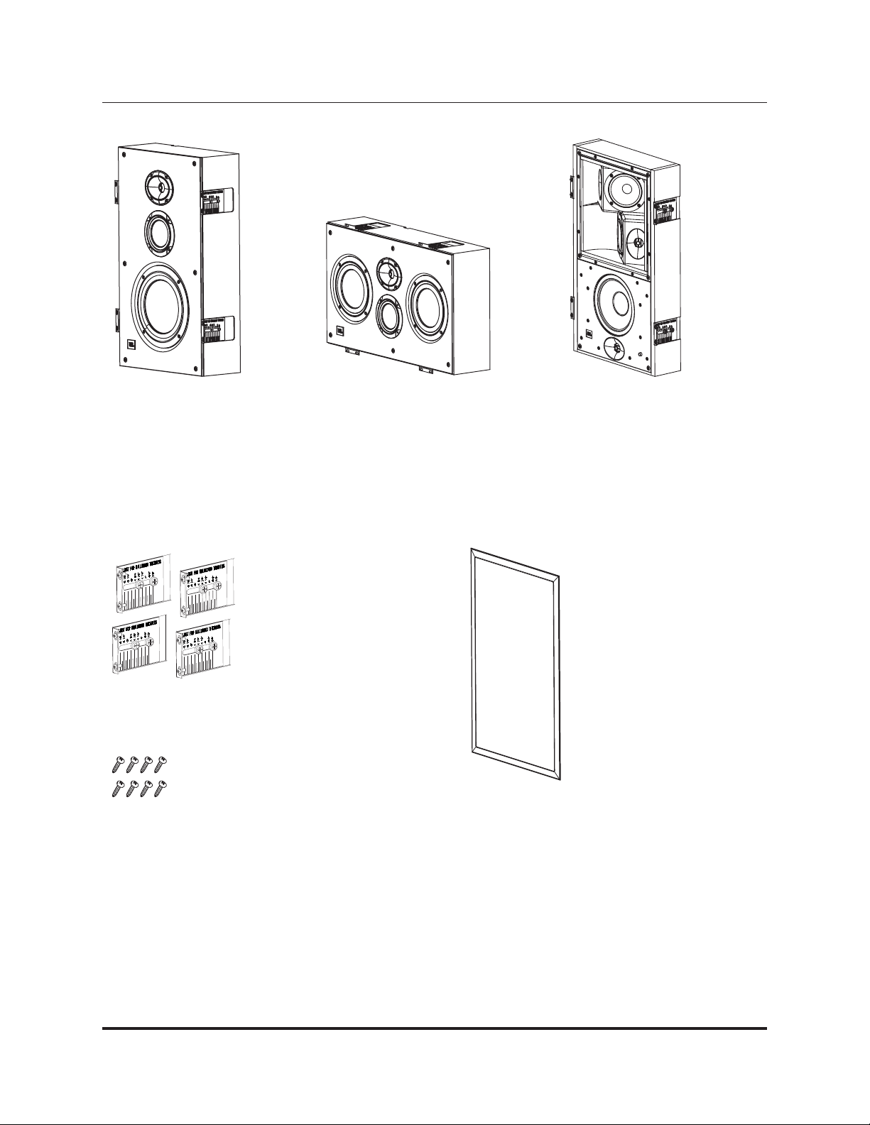
One S4HC horizontal channel
flush-mount loudspeaker
One S4VC vertical channel
flush-mount loudspeaker
One S4A multi-pole ambient
flush-mount loudspeaker
Four mounting L-brackets with
eight 1/4-20 x 3/4" screws
Eight 8-32 x 1/2" screws for
speaker installation
One grille with grille frame
INCLUDED
Page 5
Positioning your loudspeakers properly is critical in order to achieve the
sonic performance of a home theater. Please read the following section
and the “Fine-Tuning Your Audio System” section to guide you in correct
and optimal placement.
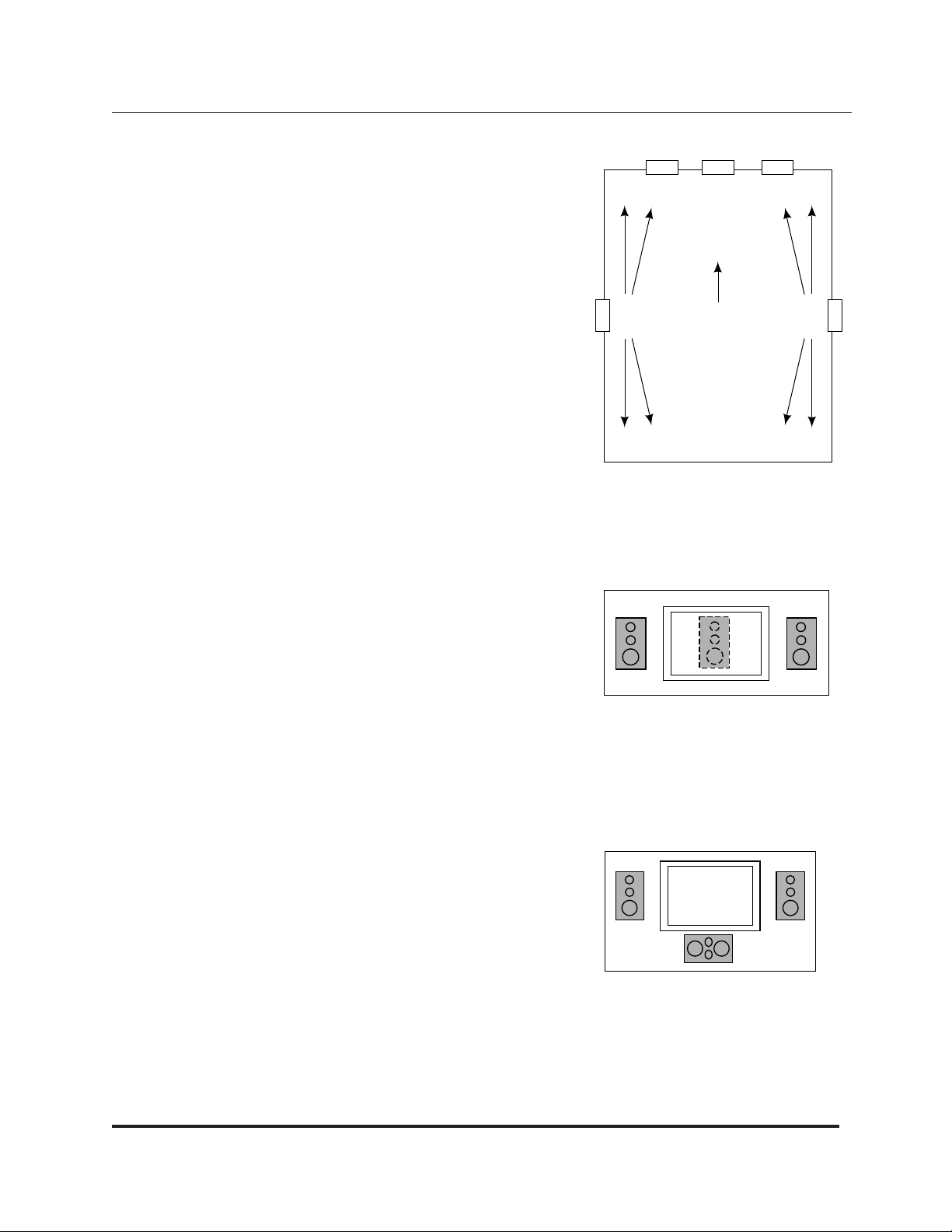
LEFT AND RIGHT SPEAKERS:If you have purchased a Synthesis Four
Digital Home Theater System, then the model S4VC will serve as your
front left and right main speakers.
Since the left and right speakers have been designed for maximum localization
of sound, they should be placed with the center of the speakers at about the
same height on screen as the actors would be, to aid in the illusion that the
actors’ voices are coming directly from their on-screen images. Ideally, the
speakers will be placed about 45 degrees apart from each other,
viewed
from the listening position, so that the distance between the speakers
is the
same as each speaker’s distance from the listener (see Figure 1).
CENTER CHANNEL SPEAKERS
S4VC:If you have purchased the vertical channel speaker (model S4VC)
for the center position, be sure to place it vertically during installation in
order to take advantage of its sound-dispersion characteristics. If you mount
it horizontally it will not provide the correct dispersion pattern. If the speaker
is being used with a perforated projection screen, it should be mounted
behind the center of the screen (see Figure 2). If a nonperforated projection
screen, plasma display or other fixed video device is being used in the
installation, the preferred center speaker is the model S4HC (below).
S4HC:If you have purchased the horizontal channel speaker (model S4HC)
for the center position, be sure to position it horizontally during installation
in order to take advantage of its sound-dispersion characteristics. If you
mount it vertically it will not provide the correct dispersion pattern.
Although the preferred speaker model to be used with a perforated projection screen is the vertical model S4VC (above), the S4HC horizontal speaker
may be used instead and should be mounted behind the center of the
screen. If a nonperforated projection screen, plasma display or other fixed
video device is being used in the installation, then the recommended
location is directly below and as close as possible to the video display
(see Figure 3), although the inverse of this method will work also.
5
5.1-CHANNEL SYSTEM
Figure 1.
Figure 2.
Figure 3.
SPEAKER PLACEMENT
RCL
VIEWING
POSITION
FLOOR PLAN
Page 6
NOTE:
It is extremely important to place the tweeter/mid-bass arrays for each of the center, left and right speakers at the
same height. The EOS waveguide containing the tweeter in the center channel speaker should be no more than two
feet higher or lower than those in the left and right speakers. This preserves the “localization integrity” of “sound
pans”, in which the sound appears to move from left to center to right. If the program material also appears to travel
up and down, it can destroy the illusion of panning effects and so should be avoided.
AMBIENT SURROUND SPEAKERS:Although it has been common for many years to use a number of surround
speakers in commercial movie houses, until recently, the traditional home theater configuration called for 5.1
channels, i.e., front left, center, front right, surround left and surround right, plus a low-frequency-effects channel.
The newer surround formats that are appearing in consumer audio equipment are calling for more complicated 6.1and 7.1-channel systems. The advantages of using additional speakers are many. Additional channels enable a more
versatile use of directionality for a more accurate surround presentation. Also, a higher overall sound-pressure level
can be achieved with less energy expenditure from any individual speaker.
Placement of the surround speakers remains critical.
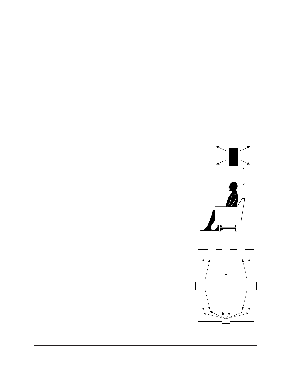
5.1-CHANNEL SYSTEMS
The S4A multi-pole ambient surround speakers work optimally if they are
placed as far back from the screen as the viewing chairs are. If there are two
rows of chairs, these speakers should be placed between them.
The ambient surround speakers should be placed higher than the seating area,
at least two feet above seated ear level (see Figure 4).
The preferred method to mount the ambient surrounds is to put them directly in
the side walls. This lets each speaker radiate to the front and back of the room
and to reflect off the side walls.
There are a few instances in which the ambient surrounds would perform
better if mounted in the ceiling rather than the walls. If one or both of the walls
are “acoustically dead”, due to the presence of windows, fabric, furniture or
other absorption, it may be necessary to turn the ambient speakers sideways
and, instead of mounting them in a vertical orientation, mount them in the
ceiling in a horizontal orientation.
6.1-CHANNEL SYSTEMS
A 6.1-channel system can be thought of as a 5.1-channel system with the
addition of a rear center speaker placed midway between the two surround
speakers, and further to the rear than the surrounds. It should be placed at the
same height as the side surround speakers (see Figure 5).
6
6.1-CHANNEL SYSTEM
Figure 5.
Figure 4.
SPEAKER PLACEMENT
Min. 2’-0"
RCL
VIEWING
POSITION
FLOOR PLAN
Page 7
7.1-CHANNEL SYSTEMS
In a 7.1-channel system, two speakers are added for rear fill, in addition to the surround speakers in a 5.1-channel system. The two additional speakers are placed on
the rear wall or near the rear wall in the ceiling (see Figure 6).
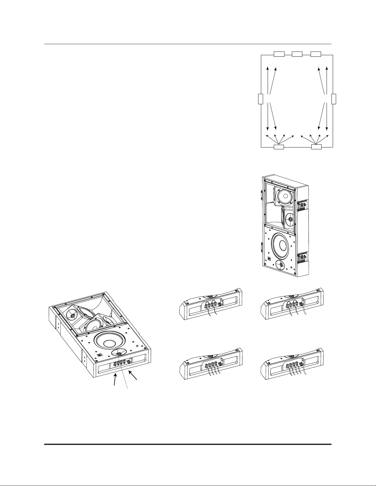
S4A MODES OF OPERATION
The S4A multi-pole ambient surround speakers feature the unique capability of
being configured in any of three operational modes. Choose between Dipolar or
Bipolar operation for cinema reproduction and Direct Radiating for music reproduction.
Both Dipole and Bipole modes are diffusive, meaning there is less energy on-axis
than off-axis relative to the front of the speaker baffle. As the illustration of the
S4A (Figure 7) indicates, the omnidirectional woofer faces toward the listening
area, while dual sets of tweeter/midrange arrays (diffuse arrays) face toward the
front and rear or from side to side in the room. In Dipole mode the arrays play out
of phase in relation to each other and in Bipole mode they play in phase with
each other.
To activate the Direct Radiating mode for music playback, use the JBLSynthesis
electronics package, including the SDP-40 surround processor, to trigger the
autoswitching relay in the loudspeakers. The input to the trigger connection is
located at the bottom of the speaker, next to the speaker terminals (see Figure 8)
and accepts 2-conductor, #24 to #16 AWG wire. The relay is activated by a constant
5V to 12V DC signal.
S4A WIRING GUIDE
Each S4A speaker can be wired in single- or dual-drive mode. The best performance can be obtained by installing
four S4A speakers in a 7-channel system and wiring them in single-drive mode; that is one amplifier channel per S4A
7
7.1-CHANNEL SYSTEM
Figure 6.
Figure 8.
Single drive – Dipole or Bipole
operation only – 2-cond. speaker
wire
Dual drive – Bipole operation
only – 4-cond. speaker wire
Single drive w/Direct – Dipole or Bipole
& Direct Radiating operation – 2-cond.
speaker wire & 2-cond. trigger wire
Dual drive w/Direct – Bipole & Direct
Radiating operation – 4-cond. speaker
wire & 2-cond. trigger wire
Figure 7.
SPEAKER PLACEMENT
SIDE
LEFT
REAR LEFT
RCL
REAR RIGHT
RIGHT
SIDE
SPEAKER INPUT #1
SPEAKER INPUT #2
Page 8
speaker. If only two S4A speakers can be used in a particular application, then they should be wired in dual-drive
mode so as to gain the advantages of a 7-channel system. Each S4A speaker receives amplification from 2 channels –
side and rear – which can only be accomplished in the Bipole mode.
WHICH DIFFUSE MODE IS THE RIGHT ONE FOR THE JOB?
D
IPOLE MODE IS TYPICALLY USED WHEN:
• The speaker is located relatively close to the
listening position.
• Multiple side or rear speakers are being used in a
small listening room.
• The speaker is mounted near, but not in, a corner
and will be subject to negative reflections from
nearby walls.
• The room is highly reflective.
BIPOLE MODE IS TYPICALLY USED WHEN:
• One speaker location is used to drive both side and
rear channels in a dual-drive configuration.
• The speaker is located relatively far away from the
listening position.
• Multiple side or rear speakers are being used in a
large listening room.
• The speaker is mounted in a corner, at a 45-degree angle.
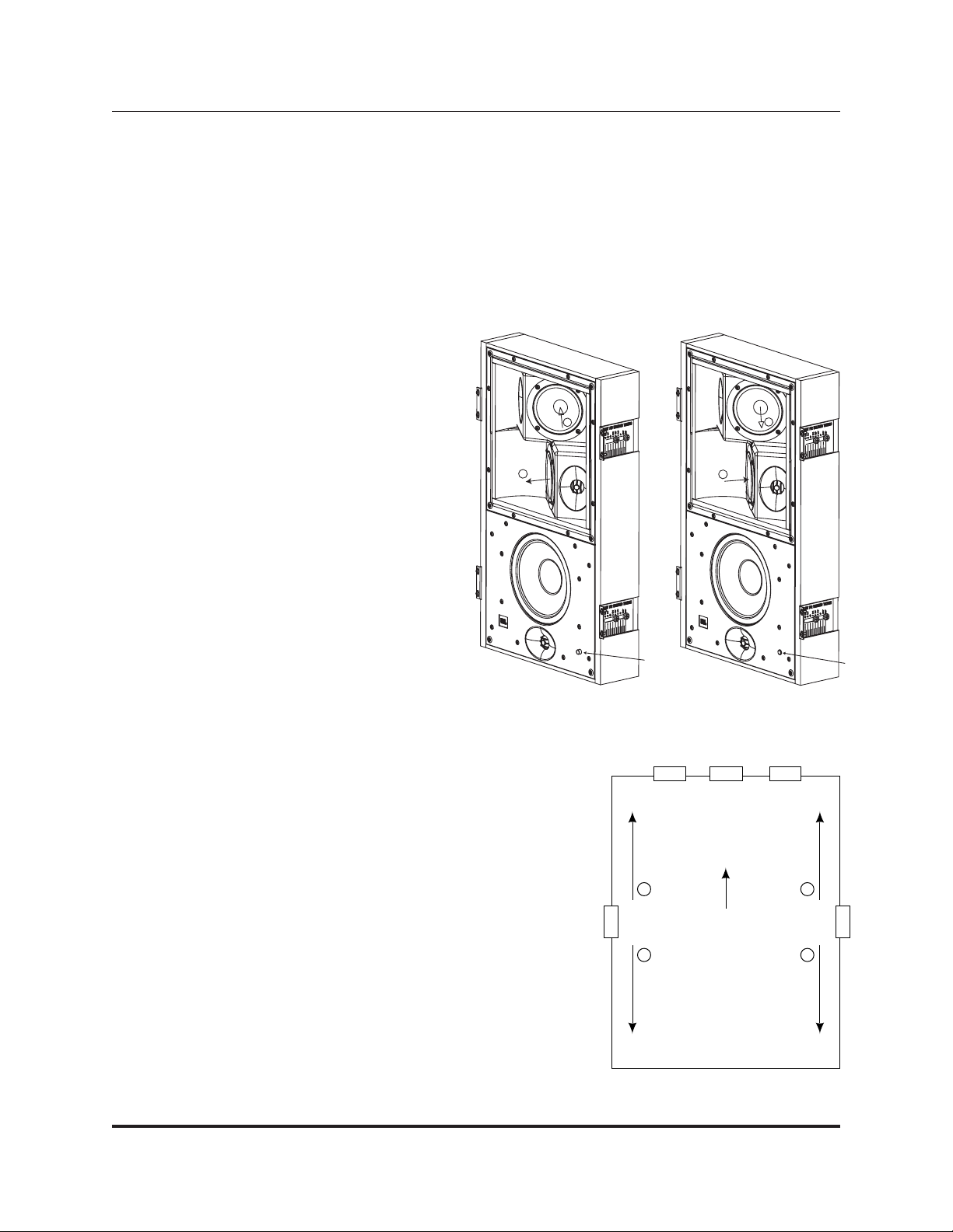
PREPARING THE S4A FOR THE CORRECT OPERATIONAL MODE
It will be necessary to choose which of the two diffuse modes to use at the
time of installation. The S4A is shipped from the factory in the Dipole mode.
If this is your choice and the speaker will be placed in the vertical orientation, no changes are required and the S4A can be directly installed into its
permanent location. For convenience, a phase switch is located on the
lower right front corner of the baffle to easily set the phase relationship to
the other surround speakers in the system (see Figure 9).
Setting the phase in relation to the other speakers in the room only applies
when the S4A speakers are set in Dipole mode.
The S4A speakers are shipped from the factory with the phase switch in the
OUT position. In this position, the positive phase array is pointing toward
8
Figure 9. Default Dipole phase relationship
Figure 10.
SPEAKER PLACEMENT
-
+
+
-
SWITCH OUT (SHIPPED) SWITCH IN (OPTIONAL)
PHASE
SWITCH
+ +
VIEWING
POSITION
– –
FLOOR PLAN
PHASE
SWITCH
RCL
Page 9

the left as you face the speaker. That is, when positive voltage is applied to
the cone, the cone will move outward. Usually, when Dipole mode is used,
the positive phase array should fire toward the front of the room. The array
facing the rear of the room will have a negative orientation. That is, when
positive voltage is applied to the cone, it will move inward, in the opposite
direction of the other array on the speaker. As shipped from the factory, the
S4A is set up for placement in the right-side wall (from the perspective of
the listening position) in a 5.1-channel system. The speaker that will be
placed in the left-side wall should have its phase switch pushed in so that
the positive phase array will be firing toward the right as you face the
speaker, which will result in its firing toward the front of the room when
installed (see Figure 10 on page 8).
In a 7.1-channel system, where two additional S4A speakers may be
mounted in the rear wall, the positive phase arrays should both fire toward
the center of the rear wall. Thus, the speaker on the left (from the perspective of someone seated in the listening position and facing the front wall)
should be configured with its phase switch in the OUT position (as shipped), and the speaker on the right should be
configured with its phase switch placed in the IN position (see Figure 11).
If Bipole mode is preferred, the upper half of the baffle must be removed to access and reconfigure the internal connection points. To engage Bipole mode, unplug the wire connector from the connector on the speaker that is marked
“Dipole” and move it to the connector marked “Bipole” (see Figure 12).
S4A ORIENTATION – VERTICAL OR HORIZONTAL
The S4A’s top baffle or “diffuse array” may be rotated 90 degrees clockwise so that the speakers can be placed in
either vertical or horizontal orientation and still be able to produce the correct dispersion pattern. An example of
when this may be necessary is if the S4A is being installed in a ceiling and the joists are running from front to back
in the room. In that situation conventional in-wall side channels would be firing side to side rather than front to back.
To correct this and produce the correct pattern, remove the eight retaining screws from the “diffuse array” and rotate
9
RCL
SIDE
LEFT
SIDE
RIGHT
REAR LEFT
REAR RIGHT
VIEWING
POSITION
FLOOR PLAN
+ +
+ +
Figure 11.
Figure 12. Connection for
Bipole mode
SPEAKER PLACEMENT
Page 10

90 degrees so the dispersion pattern is correct in relation to the room and the other surround speakers in the system.
If changing from the vertical to horizontal configuration, rotate the array clockwise. If changing from the horizontal to
vertical configuration, rotate the array counterclockwise (see Figure 13). In both cases, take care not to damage the
wiring, which will remain connected to either the Dipole or Bipole connector as discussed above (see Figure 12).
S4A DUAL DRIVE MODE
As the S4A has the capability of producing both side and rear fields from a single location in Bipole Mode while
dual-driven for cinema playback (see S4A Wiring Guide on page 7), some care must be taken when using the
Direct Radiating mode with the autoswitching trigger for music playback.
Use Speaker Input #1 (see Figure 8) for the side field so that the direct-radiating tweeter for both speakers plays the
correct information generated by the decoder. This can be accomplished by rotating the “diffuse array” 180 degrees
from default so that the speakers mirror each other in the installation.
See Figure 13, which shows how to rotate the array, but note that for Dual Drive mode you will need to rotate the
array an additional 90 degrees from the position shown for a final position in which the tweeter-midrange array that
started out on top ends up on the bottom (and thus with the tweeter facing to the right rather than the left).
MOUNTING THE SPEAKERS
SPEAKER-MOUNTING OPTIONS
The S4VC, S4HC and S4A models all use the same mounting
bracket. There are two models to choose from, based on the
type of installation. In the case of new construction, choose
the S4PCB preconstruction bracket. For retrofit installation,
use the S4RFB. Both are sold separately. The speakers will fit
into standard-construction 2" x 6" walls with 16" on-center
studs. For horizontal mounting, cross-bracing is required; also
at 16" on center. See separate instructions on mounting either
S4PCB or S4RFB, included with the brackets.
10
Figure 14.
Figure 13. Rotate top baffle for vertical or horizontal orientation
SPEAKER PLACEMENT
ROTATE ARRAY CW
SET THIS
SCREW TO
WALLBOARD
THICKNESS
Page 11

The speakers are directly attached to the mounting L-brackets with hardware supplied in the speaker packing box,
and can be adjusted for proper mounting depth with a variation of up to 2-1/2 inches. The actual depth will vary
depending on wall construction and acoustic materials applied to the wall surface (see Figure 14). To flush-mount the
grille to the wall surface, the speaker must be recessed in the wall no more than 1/4 inch. The grille pins fit directly
into the speaker cabinet via receiver bushings with 15 ft/lb of tension per pin. Use the marked speaker-depth-indicator flanges (attached to the sides of the speaker baffle) to appropriately adjust the depth from the wall surface so
that the baffle is recessed 1/4 inch. This will ensure that the grille will sit flush to the wall surface.
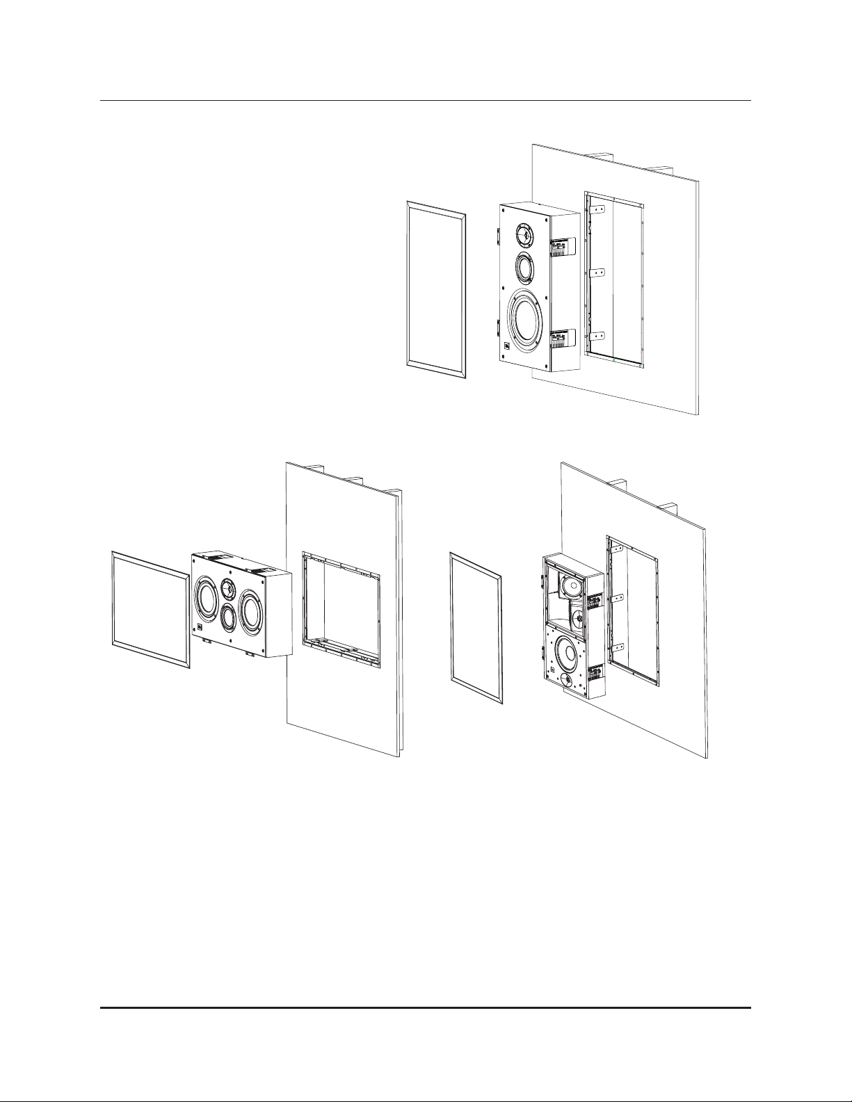
REQUIREMENTS FOR MOUNTING
OPTION 1 – NEW CONSTRUCTION:The S4PCB mounting-flange bracket must be installed before the drywall
is installed in the room. Attach the included L-brackets to the speakers (see Figure 14), and attach them to the
mounting flanges at the appropriate recessed distance. The S4VC and S4HC require a minimum 6" wall depth.
The S4A requires a minimum 4" wall depth (see Figures 15, 16 and 17).
11
MOUNTING THE SPEAKERS
Figure 15. Mounting the S4VC
speaker using the S4PCB kit
Figure 16. Mounting the S4HC
speaker using the S4PCB kit
Figure 17. Mounting the S4A
speaker using the S4PCB kit
Page 12
12
OPTION 2 – RETROFIT/PREEXISTING
CONSTRUCTION: Use the S4RFB bracket.
Mount the S4RFB to the wall surface and secure
it to studs behind the wall. Attach the speaker via
mounting flanges to the appropriate recessed
distance. The S4VC and S4HC require a minimum
6" wall depth. The S4A requires a minimum 4"
wall depth (see Figures 18, 19 and 20).
NOTE: Do not attempt to install any type of mounting bracket other than the S4PCB, the S4RFB, or any other
bracket that JBL may supply for these speakers in the future. Drilling holes in the product or improperly
installing mounting brackets may void your JBL warranty and cause a safety hazard.
A JBL factory-authorized custom installer can install appropriate brackets. Contact JBL and your installer/dealer for
additional information.
Figure 19. Mounting the S4HC
speaker using the S4RFB kit
Figure 20. Mounting the S4A
speaker using the S4RFB kit
Figure 18. Mounting the
S4VC speaker using the S4RFB kit
MOUNTING THE SPEAKERS
Page 13

13
To connect the Synthesis Four loudspeakers to the power amplifiers or receiver, use 2-conductor insulated speaker
wire. We recommend #14 AWG wire as a minimum size. Your JBL dealer can recommend suitable cables.
Both the S4VC and S4HC utilize push-style friction binding posts that can accommodate up to #10 AWG stranded wire.
Since the S4A can be configured in three different ways, be sure to run the correct number and type of wires. Refer
to the S4A Wiring Guide on page 7.
PREPARING THE HOOKUP WIRE
1. First determine the distance between your amplifier and the most distant speaker in each group (fronts, surrounds,
back surrounds, subwoofers).
2.
Now make the hookup wires for all speakers in each group this length, even if one speaker is much closer
to your
amplifier than the other. This will help maintain proper signal balance.
3. Strip off 3/8" of insulation from both ends of each conductor.
4. Twist each set of standard wires into a tightly bunched spiral.
5. Speakers and electronics terminals have corresponding (+) and (–) terminals. Most manufacturers of speakers and
electronics, including JBL, use red to denote the (+) terminal and black for the (–) terminal, although some electronics
manufacturers have adopted the new color-coding standard promulgated by the Consumer Electronics Association. In
that case the positive terminal will be colored to correspond to the channel position, while the negative terminal will
be colored black.
It is important to connect all speakers identically: (+) on the speaker to (+) on the amplifier and (–) on the speaker to
(–) on the amplifier. Wiring “out of phase” results in thin sound, weak bass and poor imaging.
With the advent of multichannel surround sound systems, connecting all of the speakers in your system with the correct polarity remains equally important to preserve the proper ambience and directionality of the program material.
Now find a visual difference between the two conductors of each molded pair of speaker wire. Differentiating marks
can be a different color wire (copper or silver); a strand of yarn in one conductor; thin, raised ribs on one part of the
outer insulation; or a printed marking on one part of the outer insulation. It doesn’t matter which of the two strands
go to the (+) and (–) on the speakers and amplifiers, as long as all speakers are connected identically. Push down on
the binding post, insert the wire into the hole, and release.
CONNECTING THE SPEAKERSTO THE REST OF YOUR SYSTEM
Page 14

14
ACOUSTICAL PROBLEMS IN LISTENING ROOMS
A home THX audio system, such as the Synthesis Four system, addresses many of the problems common to high-quality
reproduction of music or soundtracks in a home environment. For example, the dispersion pattern of the front LCR speakers
minimizes the effects of floor and ceiling reflections. Still, the single most important variable in any sound system is the
listening environment. Room reflections create spurious false images and “comb filter” interference effects that alter the
tonality of the system while degrading the localization of specific sounds. Larger rooms sustain echoes that degrade
dialogue intelligibility and detail. All rooms have standing waves that emphasize certain frequencies at the expense of
others, based on the dimensions of the room.
Other concerns include environmental noise, which is often greater than people realize. Although they might become
accustomed to its presence and “tune it out,” it still reduces the perceived low-level resolution of the system. In
addition, the profound bass capabilities of a home THX audio system can create distracting rattles that lesser
systems might never evoke.
This section of the manual contains a variety of suggestions for addressing some of the peculiarities of the listening
environment to improve the accuracy of your Synthesis Four system’s sound reproduction.
ROOM REFLECTIONS
The most troublesome room reflections are usually
the early reflections of the front LCR speakers off
the floor, ceiling and side walls. These reflections
reach the listener’s ears delayed with respect to
direct sounds and blur the perceived image. They
can also degrade dialogue intelligibility through the
same mechanisms (see Figures 21 and 22).
The design of the Synthesis Four speakers minimizes the floor and ceiling reflections. As an extra
enhancement, it is often a good idea to place a
thick, absorptive carpet between the front speakers and the listening position, just to further
reduce this primary reflection from floors with hard
surfaces. A rug made of wool will generally have
more uniform absorption characteristics than one
made from synthetic fibers.
JBL Synthesis Four speakers have broad dispersion
in the horizontal plane in order to ensure a wide
usable listening area. This design choice can induce
reflections off the side walls, especially in installations where they are relatively close to the front
speakers. With conventional speakers, these reflections can be reduced simply by angling the left and
right speakers inward somewhat.
FINE-TUNING YOUR AUDIO SYSTEM
Figure 21.
Figure 22.
t1t
t
1
t
2
Copyright 2000 Lucasfilm Ltd.
Resultant Frequency Response From Reflection
Sound Level
+6dB
0dB
2
Direct
Reflected
Result: (+6dB)
Direct
Reflected
Result: (–∞dB)
An Additive
Frequency
A Canceling
Frequency
Frequency
Peak and dips at various frequencies
Copyright 2000 Lucasfilm Ltd.
Page 15

15
However, since it is not possible to “toein” flush-mounted speakers, the next
step is the strategic placement of
absorptive materials on the side walls.
These range from commercially available fiberglass and dense foam to heavy
draperies and even large, overstuffed
furniture. The optimal position for these
materials can be found with a small
hand mirror and the help of an assistant.
Sit at the primary listening position and
have the assistant slowly slide the mirror along the wall. When you can see
any of the front speakers reflected in the
mirror, mark the wall at the mirror for
later placement of absorptive material
(see Figure 23).
A variation of this method is especially helpful in rooms that are already fairly “dead” acoustically. Rather than using
absorptive material in rooms like these, try using diffusion instead. Commercially built diffusers are available but large
bookcases and irregularly shaped furniture will also serve the same purpose. They reflect sounds in a highly randomized way that effectively “scatters” the sound in all directions. Place the diffuser where you would otherwise place the
absorptive material (using the “mirror trick”), to break up the first early reflections and scatter them randomly throughout the room.
Commercially available fiberglass, foam and diffusion panels may not be aesthetically acceptable in many installations, particularly when the home theater room serves multiple purposes. All of these materials can be covered with
acoustically transparent cloth for design considerations. It is important that the cloth be acoustically transparent,
however, or the effectiveness of the absorptive material will be greatly reduced. The simplest test for this is to hold a
large sample of the cloth in front of a speaker playing pink noise. If you can move the cloth in front of the speaker
without hearing a difference, the cloth is good for use in this application.
Large expanses of glass can be challenging. Glass reflects mids and highs but often lets bass pass through, almost
as if the glass were not there. The result is a characteristically bright, rough sound that can be difficult to correct
electronically. The best treatment is generally the heaviest insulated drapes that can be found. (Incidentally, these
serve double duty, controlling light that might otherwise fall on the screen.)
The materials just discussed are ineffective at lower frequencies. See the discussion on standing waves for more
information about treating environments with low-frequency response problems.
EXCESSIVE USE OF ABSORPTIVE MATERIALS
Absorptive materials should be used judiciously, as overuse can acoustically deaden the room and create additional
difficulties. While the ideal home theater should be considerably “deader” acoustically than a typical living room, it
still needs some reflectivity and diffusion. In particular, the surround speakers depend on nonabsorptive surfaces for
their operation, since they radiate virtually no sound directly at the listeners.
Figure 23.
FINE-TUNING YOUR AUDIO SYSTEM
SOLUTIONS TO ROOM REFLECTIONS:
DIFFUSION AND ABSORPTION
Loudspeaker
Loudspeaker
Reflected Path
Reflected Path
Reflected Path
Reflected Path
Direct Path
Absorptive Material Absorptive Material
Direct Path
Listener
Listener
Page 16

16
The best arrangement of the absorptive and nonabsorptive surfaces in the room can be seen in Figure 24. Most of
the room surfaces are relatively absorptive, with the notable exception of the rear wall and the highest portions of
the other walls, which should be diffusive.
“SLAP” ECHOES
“Slap” echoes are common in rooms that have parallel walls with little
or no absorption or diffusion. Sounds tend to bounce back and forth
between the parallel walls many times before they die out, causing a
characteristic bright, “zingy” sound and interfering with the intended
tonal balance and acoustic nature of the soundtrack (see Figure 25).
Walk slowly through the room, clapping your hands. No clear reflections
should be heard at any point in the room – especially not near the primary seating area. Listen for a “flutter echo” of the hand clap (a rapidly
repeating percussive sound, indicative of the sound bouncing between
two parallel walls). Again, the best home theaters are fairly “dead”
acoustically. This allows the program material and the playback system
to create the environment, rather than having the room’s native acoustic
signature color everything.
The solution for slap echoes is usually a combination of absorption and diffusion. Specifically, place absorptive material behind the front speakers (heavy drapes, fiberglass, dense foam) and elements that will facilitate diffusion in the
rear of the room (bookcases, irregularly shaped furniture, etc.). This will effectively suppress the slap echoes while at
the same time providing a diffusive surface in the rear for the surround speakers. This enhances the enveloping characteristic of the surrounds even further.
In those relatively rare cases where you have the luxury of building the home theater room as new construction, consider using nonparallel surfaces in the construction of the room. A difference of as little as 6 degrees will break up
the slap echoes very effectively. For example, “flaring” the side walls out from the front by approximately 6degrees
Figure 24.
Figure 25.
FINE-TUNING YOUR AUDIO SYSTEM
ROOM ABSORPTION FOR HOME THEATER SYSTEMS
Surround speaker
Screen speaker
• “Dead” zone absorbs
front-speaker reflection
• “Live” zone provides
surround propagation
Loudspeaker
Listener
Copyright 2000 Lucasfilm Ltd.
Page 17

17
and having the ceiling rise toward the rear of the room at a comparable rate will do wonders for the room’s
acoustics, if the wall design is solid and the angles are clearly intentional from the outset.
RATTLES
Rattles in the room are structural resonances (as opposed to standing waves, which are airborne resonances) that the
system may stimulate due to its broad frequency response and wide dynamic range. They are particularly prominent for
sounds in the lower frequencies, and can sound like distortion. Sources of rattles include: furniture, loose window
frames, walls, lighting fixtures, ventilation systems and even knickknacks on various shelves around the room. The simplest way of identifying these rattles is by using a rattle test. This is an
extremely
slow low-frequency sweep from 20Hz
to 500Hz, recorded at reference level. 10dB of output level increase over standard level might be necessary to allow
hearing all the room rattles. Be careful with this test, as it is also a severe test of associated amplifiers and speakers.
As the sweep makes its way up the frequency range, you will probably find a surprising number of rattles in your room.
All of these rattles will occur at one time or another during music or movies, but are usually perceived as background noise
or distortion in the system.
Once identified, eliminating the rattles is usually straightforward. As an example, small pieces of felt can be affixed
to the back of a painting (in the frame’s bottom corners) to prevent audible rattles against the wall. Likewise, strips
of felt can be wedged into a loose window rattling in its frame. Recessed lighting fixtures can be tightened up. A
piece of cloth can be placed under offending knickknacks.
Every home THX audio system should be subjected to the rattle test at least once – the difference in low-level
resolution and in freedom from pseudodistortion is sometimes large and the effort involved is quite small.
BACKGROUND NOISE
The effect of background noise on system performance is dramatic, yet often overlooked. Most people might think of
it merely as a minor inconvenience, yet it has a profound effect on the way we perceive sound.
The presence of more-or-less constant background noise alters the way we perceive volume, since subjective loudness is a relative measure. In a quiet room, even a 70dB SPL sound can seem fairly loud. In a noisy convention center,
the same volume would be barely audible. Since there is a practical upper limit to both the volume to which we
should expose ourselves and the volume a given system can reproduce, having a relatively noisy environment effectively limits the perceived dynamic range of the program material. This, in turn, limits the dramatic effect that might
have been intended by the director (or the performer, if listening to music).
Constant background noise also obscures, or masks, low-level signals that are frequently important in films. Many
scenes use subtle ambient noises to set the mood prior to an important event – without the full perception of the
whispered secret or the barely heard creaking of a door, the impact of the scene is diminished.
It has been demonstrated that even a relatively narrow-bandwidth noise can effectively reduce our hearing acuity
over a broad range of frequencies, far greater than the noise itself. When you add up all the various sources of noise
from electric motors, noisy heating/cooling systems and outside noises, plus noises that even audio and video components can introduce such as noisy transformers, motors in laser players or projector fan noise, our ability to discern
the low-level information in the soundtrack is greatly compromised – and the director’s intention along with it.
FINE-TUNING YOUR AUDIO SYSTEM
Page 18

18
BACKGROUND-NOISE SOLUTIONS
Many sources of noise in a home environment can be addressed simply. Locating the home theater in the basement often
removes it from many household noises as well as isolating it from other family members. Taking care to completely seal
windows and doors can also make a significant difference in reducing outside noise.
Heating and cooling systems are more challenging. Sometimes, the answer may be as simple as using a “whistle-
free”
diffusion grille rather than one that creates undue noise from turbulence. In cases of new construction, using largerdiameter air ducts for lower air velocity is very beneficial. You can go further by using ductwork that is lined with
acoustically absorptive material. Where possible, longer ducts that have several turns further reduce the sound of the
airflow by eliminating the straight path from the heating/cooling system to the room.
Some of the construction techniques used to minimize the transmission of external sounds into the listening environment include:
• Double or triple layers of drywall (gypsum board)
• Double wall construction, meaning two complete sets of studs (preferably stuffed with fiberglass insulation)
• Double wall construction with staggered studs (minimizes transmission of vibrations from one set of studs to the
next)
• Floating floor construction (again, preferably stuffed with fiberglass; this also can enhance the perceived bass,
since the subwoofers may cause structural vibrations through the false floor that then can be transmitted up through
furniture)
• Seal all windows, doors, vents
• Seal and caulk all apertures in the wall (electrical outlets, through-wall plumbing, etc.)
Finally, transient noises (traffic on the street, dripping faucets, etc.) distract your attention away from the program
material and remind you that you are in your home theater/living room rather than placing you in the midst of the
action of a movie.
STANDING WAVES
A “standing wave” is what causes a pipe of a particular length in a large
pipe organ to have its characteristic pitch. The pipe literally amplifies certain frequencies, based on its length and the wavelength of the frequency.
A typical rectangular room has three characteristic “lengths” and, thus,
three fundamental standing wave frequencies. In addition, multiples of
these frequencies are also amplified. These frequencies are often referred
to as “room resonances” or “room modes,” i.e., the frequencies at which
the room tends to vibrate of its own accord. These resonances lead to
uneven frequency response, the greatest problems being in the 60Hz –
150Hz range for a typical living room (at lower frequencies in larger rooms).
See Figures 26 and 27.
Unfortunately, there is no way to eliminate the effects of standing waves
completely. The best that can be done is to minimize their effect through a
variety of strategies.
Copyright 2000 Lucasfilm Ltd.
Loudspeaker
Listener
Figure 26.
FINE-TUNING YOUR AUDIO SYSTEM
Page 19

19
STANDING-WAVE SOLUTIONS:
R
OOM RATIOS
In new construction, the best way to minimize
the audibility of standing waves is to plan for
an even distribution of them, so that their
effects do not “pile up” on top of each other. In
this regard, the ratios of room dimensions are
the critical factor. Rooms having equal dimensions are the worst, since the standing waves
in all directions reinforce one another. Room
dimensions that are even multiples of one
another should also be avoided where possible.
STANDING-WAVE SOLUTIONS: SPEAKER PLACEMENT
Speaker placement also has an effect on standing waves and their audibility. In particular, placement of any speaker
(including subwoofers) where two walls and the floor meet will tend to stimulate all of the available standing waves,
causing the most irregular response. The displacement required to minimize a particular
standing wave depends on its frequency, with
lower frequencies requiring more movement
owing to their longer wavelengths. As a result,
minimizing colorations due to standing waves
often requires significant adjustment of subwoofer placement. Leave yourself some latitude
with regard to subwoofer placement when planning your system – the final adjustment will
probably have to be done on something of a
trial-and-error basis. See Figures 28 and 29 for
some suggestions.
STANDING-WAVE SOLUTIONS:
A
BSORPTION
In theory, it is possible to dampen standing
waves with absorptive material. The difficulty is
that the thickness of the absorptive material
would have to be approximately one-half the
wavelength of the lowest frequency requiring
damping. This means a five-foot thickness of
fiberglass would be required in order to damp
everything down to 100Hz – not very practical.
Copyright 2000 Lucasfilm Ltd.
SUB
Low Relative PressureLow Relative Pressure
Figure 27.
Figure 28.
Figure 29.
FINE-TUNING YOUR AUDIO SYSTEM
Resulting Modal Structure
+
Subwoofer
Copyright 2000 Lucasfilm Ltd.
• How to improve a
2nd-order standing
wave
•
Listener
–
+
The subwoofer
drives the + and –
areas equally,
resulting in reduction
of resonance
Resulting Modal Structure
+
Subwoofer 1
Copyright 2000 Lucasfilm Ltd.
Mono!
–
Subwoofer 2
Listener
+
Subwoofer
Output
From
Controller
• Improving a 2nd-order
standing wave
– Connect the 2
subwoofers together as
“in-phase”
– The 2 subwoofers drive
the + and – areas
equally, resulting in
reduction of resonance
– Experiment a lot
Page 20

20
Standing-wave energy tends to be concentrated in the corners of rooms, which is why placing a subwoofer in the corner tends to increase its bass output. Because of this, it is possible to break standing waves up somewhat by “breaking up” the corner. This can be accomplished by placing a column of thick, absorptive materials in the corners (covered
by acoustically transparent cloth, of course). The column ought to be at least a foot on a side, and run from floor to
ceiling. A variation on this is to run an absorptive panel diagonally across the corner, leaving open air space behind it.
Both of these techniques are easily tried and sometimes quite effective.
STANDING-WAVE SOLUTIONS: ROOM EQUALIZATION
If a room exhibits severe standing-wave problems, the best solution is to know your own limitations: hire a trained
acoustician. These professionals have the necessary background to analyze the various room modes and recommend
appropriate action. This will sometimes take the form of a custom-designed bass trap, which may be easily constructed. But it takes specific skills to determine its optimal design.
In other cases, careful analysis and parametric equalization may be appropriate. Optimize everything else that you
can, then use EQ, if necessary, to “touch up” the room. This is its best use. Parametric equalization must be applied
with care and a light touch to obtain optimum results. Professionals use it all the time, with excellent results –
because they know its limitations and how to apply it.
Never equalize a room by ear. Room analysis is not as straightforward as it may seem. The analysis should
be done
using equipment with at least one-third-octave resolution, using both spatial and temporal averaging.
In any event, rooms requiring this level of treatment are relatively rare, and the skills necessary to handle them prop-
erly are highly specialized. Do not hesitate to use the professional services of an acoustician when you need them.
FINE-TUNING YOUR AUDIO SYSTEM
Page 21

21
SYMPTOM PROBABLE CAUSE SOLUTION
No sound coming •Amplifier not turned on •Turn on amplifier.
from speaker
•Amplifier gain is low •Make sure that there is
amplifier gain for that channel.
•Correct source not •Select proper source.
selected or turned on
•Defective patch cords to amplifier •Check/replace patch cords.
•Speaker wires not •Check speaker wire
connected to amplifier connection to amplifier.
•Balance control set improperly •Make sure Balance control is set
at center, or 12 o’clock, position.
•Speaker wires damaged •Make sure none of the speaker wires
or shorted are frayed, cut or punctured. Make sure
no wires are touching other wires or
terminals and creating a short circuit.
•Speaker not configured •In Dolby* Digital or DTS
®
mode, make
correctly sure that the receiver/processor is
configured so that the speaker in
question is enabled.
•Center speaker is configured •In Dolby Pro Logic* mode, make sure the
incorrectly center speaker is not in phantom mode.
•Problem not diagnosed •To diagnose the likely source of the
problem, it is often helpful to switch the
nonfunctioning speaker with one that
is functioning correctly. Turn off all
electronics before exchanging the
speakers. Turn everything back on, and
determine whether the problem is in the
same place, or has moved with the
speaker. If the problem is in the same
place, the source is most likely with your
receiver or amplifier. If the problem has
followed the speaker, then contact your
authorized JBL Synthesis custom installer or
dealer for further assistance. If that is
not possible, visit our Web site at
www.jblsynthesis.com for further information.
TROUBLESHOOTING
Page 22

22
SYMPTOM PROBABLE CAUSE SOLUTION
Bass is very weak •Subwoofers are wired out •Make sure that positive terminals on the
of phase subwoofers go to the positive terminals
on the amplifiers (red) and do the same
for the negatives.
•Subwoofers have not •Experiment with different locations.
been placed optimally
Poor or smeared imaging • Poor room acoustics •Use absorptive materials to minimize
early reflections.
•Aim speakers at listening area.
•Poor program source •Check another program source.
•Improper polarity •Check polarity of wire connections.
Indistinct dialogue •Slap echoes •Add absorption or diffusion materials.
•Miscalibration of center •Check output levels of surround processor.
channel output level
Uneven surround coverage •Poor speaker placement, •Place surrounds according to THX
strong reflections specifications.
•Add absorption and/or diffusion materials.
•Excessive absorption near •Remove absorptive material to provide
surrounds surround reflections.
TROUBLESHOOTING
Page 23

SPECIFICATIONS
23
MODEL # S4VC S4HC S4A
Description
3-Way 8" vertical 3-Way dual 6-1/2" horizontal Configurable-array flushflush-mount speaker flush-mount speaker mount surround speaker
Power Handling 250W 250W 200W Single-driven or
175W-per-array dual-driven
Nominal Impedance 6 Ohms 6 Ohms 6 Ohms
Sensitivity (2.83V@1M) 91dB 91dB 91dB
Frequency Response 65Hz – 20kHz 65Hz – 20kHz 80Hz – 20kHz
Crossover Frequencies 600Hz, 3.5kHz 600Hz, 3.5kHz Dipole Mode: 400Hz;
Bipole Mode: 800Hz, 3.6kHz,
Direct Mode: 2.5kHz
Bass Transducer(s) 8" Titanium-alloy inverted- Dual 6-1/2" titanium-alloy 8-Inch dual-voice-coil
dome with rubber surround inverted-dome with rubber inverted-dome with rubber
and cast basket, shielded surround and cast basket, surround and cast basket
shielded
Midrange Transducer(s) 4" Titanium inverted-dome 4" Titanium inverted-dome Dual 4-inch neodymium
with rubber surround and with rubber surround and full-range with rubber
cast-aluminum basket, cast-aluminum basket, surrounds and castshielded shielded aluminum baskets
High-Frequency 1" Pure-titanium-dome with 1" Pure-titanium-dome with Triple 1" pure-titanium-dome
Transducer(s) rubber surround, shielded, rubber surround, shielded, with rubber surrounds,
with EOS waveguide with EOS waveguide shielded, with EOS
waveguide
Dimensions (H x W x D) 23-7/8" x 14" x 5-1/2" 14" x 23-7/8" x 5-1/2" 23-7/8" x 14" x 3-3/4"
Weight 26 lb 32 lb 23 lb
Connectors 2-Conductor push-type, 2-Conductor push-type, Speaker: 4-conductor push-
10 –16 gauge 10 –16 gauge type, 10 –16 gauge; Control:
2-conductor screw terminal,
16 – 24 gauge
* Trademarks of Dolby Laboratories.
DTS is a registered trademark of Digital Theater Systems, Inc.
THX is manufactured under license from Lucasfilm Ltd. Lucasfilm and THX are registered trademarks of Lucasfilm Ltd.
Page 24

JBL Consumer Products
250 Crossways Park Drive
Woodbury, NY 11797
8500 Balboa Boulevard
Northridge, CA 91329
(818) 830-8757
www.jblsynthesis.com
Part No. 338636-001
A Harman International Company
 Loading...