

Page 1
S4800
3-WAY
FLOORSTANDING
SPEAKER SYSTEM
®
OWNER’S GUIDE
Page 2
TABLE OF CONTENTS
3 PREFACE
4 CHAPTER 1 – THE S4800 LOUDSPEAKER:
8 CHAPTER 2 – UNPACKING THE S4800 SYSTEM
8 CHAPTER 3 – SELECTING CABLE
9 CHAPTER 4 – AMPLIFIER RECOMMENDATIONS
10 CHAPTER 5 – PLACEMENT AND SETUP CONSIDERATIONS
11 CHAPTER 6 – S4800 SWITCH OPERATIONS
11 CONTROLS AND CONNECTIONS
15 CHAPTER 7 – CARE AND MAINTENANCE
16 CHAPTER 8 – TROUBLESHOOTING AND SERVICE GUIDE
17 S4800 SPECIFICATIONS
A TRIUMPH IN ACOUSTICS AND TECHNOLOGY
2
Page 3

PREFACE
hank you for selecting a JBL
T
®
S4800 loudspeaker system. It
represents the sum total of our
research and developmental
efforts in sound reproduction over
the last half-century. We have
labored to create a loudspeaker
system with no acoustical or electrical limitations whatsoever. While
the S4800 loudspeaker is itself a
new development, the goal behind
it goes right back to the earliest
days of the original James B.
Lansing Sound Company.
But it is your listening pleasure that
ultimately determines how successful we are in this endeavor. It is
solely in the interest of ensuring a
perfect listening experience that
we ask you to faithfully follow the
setup and operation procedures
outlined in this owner’s guide.
his guide exists for several
T
purposes. As your owner’s manual,
it contains all necessary background information and detailed
instructions for setting up your
S4800 loudspeaker system, including unpacking the loudspeaker;
selecting the correct location,
speaker wire, wiring scheme and
amplification; and connecting it
to its associated electronics.
This information will be found in
Chapters 2 through 6. In addition,
we have included a detailed
description of the S4800 speaker
(Chapter 1)
become thoroughly
so that you may
acquainted
with its unique design and
technological features.
Although physically and materially
imposing, the setup procedure of
the S4800 loudspeaker system is
relatively simple. We strongly
urge you to read this manual
thoroughly before you begin, and
consult it frequently throughout
the process. Considerations must
be made in placing the speakers;
their stature and weight make
it imperative that you become
familiar with the entire setup
process in advance.
lease take a moment to register
P
your product online at www.jbl.com.
Registration enables us to keep
you posted on our latest advancements, and helps us to better
understand our customers and
build products that meet their
needs and expectations.
3
Page 4
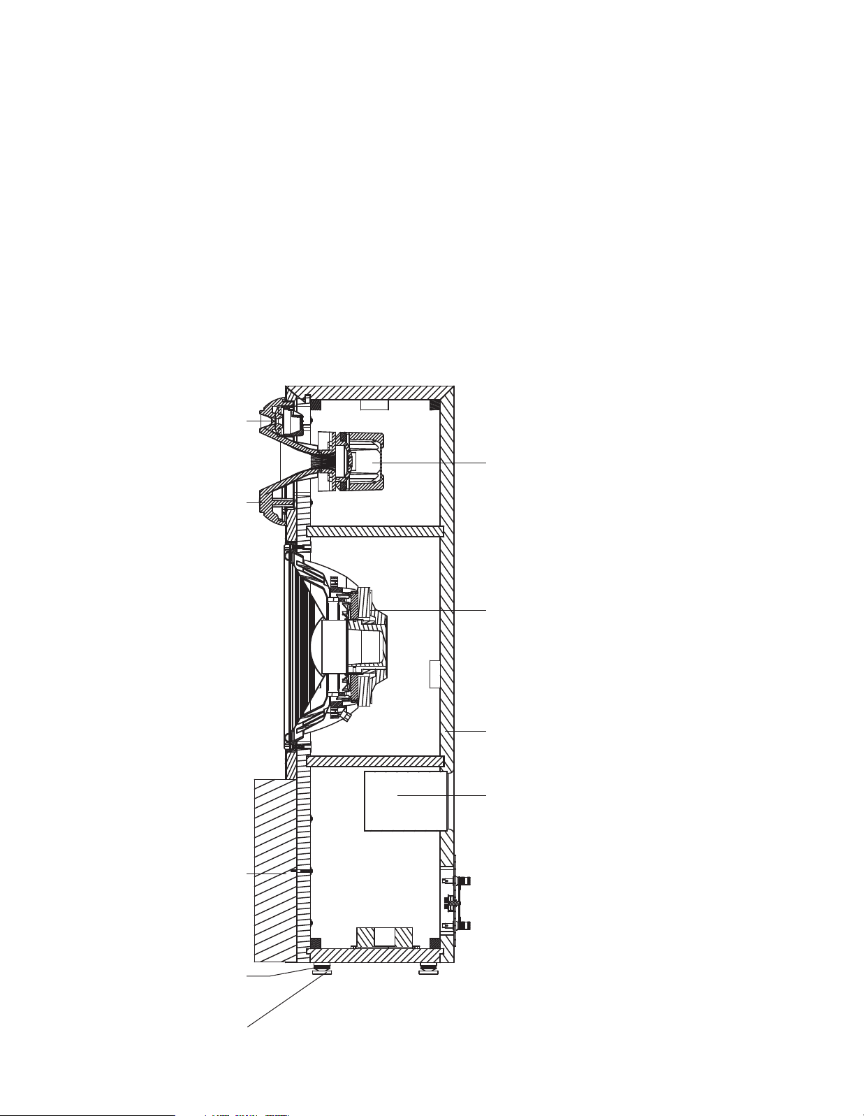
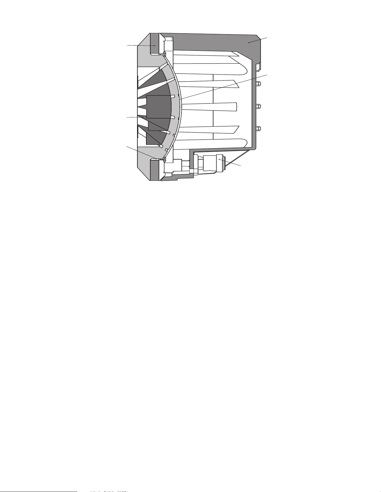
SonoGlass
Bi-Radial Horn
1
00˚ Horizontal
6
0˚ Vertical
Curved
Dress
Panel
Spiked Feet
Foot Base
1" MDF
Construction
1500FE
15" LF
Driver
Port
Tube
435AL
3" HF
C
ompression
Driver
045Ti 1" UHF
C
ompression
Driver
HAPTER 1 – THE S4800 LOUDSPEAKER:
C
A TRIUMPH IN ACOUSTICS AND TECHNOLOGY
The new S4800 employs a 3-way,
three-driver design, incorporating
an ultrahigh-
ression driverand horn to repro-
p
frequency (UHF) com-
duce high frequencies up to 40kHz.
With the UHF handling the ultrahigh
frequencies, the high-frequency
(HF) transducer could then be
upgraded to a new design using a
3-inch diaphragm for better reproduction of lower frequencies and
better blend with the woofer than
the older generations’ 2-inch
diaphragm. Both compression
drivers are mounted
in a unique
combination Bi-Radial®horn structure, precision-molded from JBL’s
roprietary SonoGlass
p
™
aterial, an
m
extremely dense and mechanically
inert substance that is easily
molded into the unusual shapes
required for superior acoustic
performance.
In order to re-create the extremely
high dynamic range provided by
today’s audio sources, a new low-
requency transducer was used,
f
incorporating a ferrite magnet, 3inch edge-wound voice coil, and
an Aquaplas-coated 15-inch cone
made of Kevlar®composite, a mixture of Kevlar fiber and pulp material that provides increased rigidity.
An EPDM rubber surround was
chosen for both its flexibility and
long life. The Symmetrical Field
™
Geometry
(SFG™) magnetic structure minimizes second harmonic
distortion by providing a uniform
flux field that prevents uneven
cone movement. The rigid castaluminum frame is also designed
to minimize distortion, as aluminum has no effect on the magnetic field. Extensive computeraided engineering and design effort
made to develop the optimized port
tuning employed in the S4800 has
resulted in a significant advance in
the concept of state-of-the-art bass
reproduction. This proprietary alignment method offers the best damping characteristics and provides
extremely fast alignment, eliminating the typical “bass-reflex” sound
of a ported system.
All three transducers are built using
the most advanced materials and
precision manufacturing techniques
refined from renowned JBL
profes-
sional sound systems.
High power
-handling capability
results in no limitations on the types
of source material.
very high input sensitivity;
The S4800
even a
has
relatively small high-end amplifier
can provide full dynamic range
without compression.
Despite its power and sophistication, the S4800 embodies both tradi
tion and technology
. It reflects the
design, engineering and manufacturing expertise derived and refined
through nearly six decades of
experience that are the exclusive
province of one loudspeaker
builder – JBL.
-
4
Figure 1. Cutaway view of S4800 speaker system.
Page 5
Terminal Base:
Glass-Filled ABS
Terminals:
Gold-Plated 5-Way
Binding Posts
Magnet:
Ceramic
Back Plate:
Steel SAE-1008
Pole Sleeve:
High-Purity Copper
Voice Coil:
Aluminum Ribbon Wire
ES-1350 on High-Temp
Fiberglass Former
Cone Body:
Special PaperPulp Composite
Frame:
Cast 380
Aluminum
Trim Ring:
NBR Rubber
Spider Spacer:
Extruded Aluminum
6063
Dust Dome:
Paper-Pulp
Composite
Spiders:
Nomex
®
Pigtail Leads:
Silver-Plated
Cadmium Copper
w/Conex Core
Polepiece:
Steel SAE-1008
Surround:
EPDM Foam Rubber
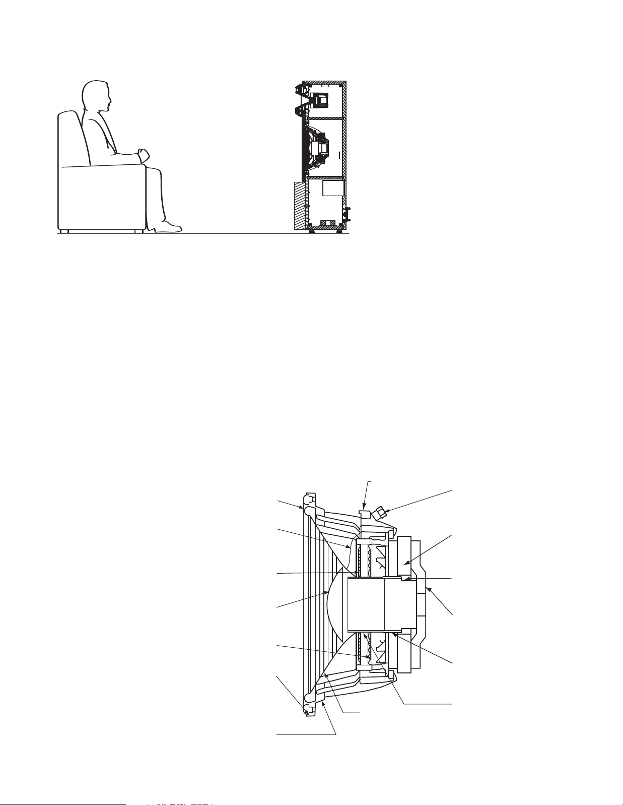
Figure 2. Height of S4800 speaker system in relation to listener
The following sections describe
the primary features and components of the S4800 loudspeaker
system.
The enclosure of the
S4800
is
specially designed to transfer
unwanted mechanical energy
away from any acoustically active
surfaces, virtually eliminating
coloration.
The massive enclosure, along
with its specially designed brass
modular feet, couples directly to
the floor, and the system literally
becomes a structural part of its
environment. Any vibration is
transmitted harmlessly down the
channel provided by the ring/
disc axes and into the floor. The
SonoGlass combination horn
maintains a smooth energy
transmission path.
S4800
The
arrangement represents the best
transducer/enclosure
possible balance of the various
tuning options and avoids the
mid-bass response buildup found
in other vented systems. Response
works with, rather than against,
the effects of “room loading.”
The unique design of the system
is the platform for its equally
unique acoustical attributes.
the sound seems to come from the
combination horn. Music imaging
s more realistic
i
appears to emanate from one point
and not from multiple
ferent times.
The S4800
em without regard to frequency.
t
Careful horn design enables the
loudspeaker to strictly adhere to a
100° horizontal/60° vertical coverage pattern. This controlled coverage arrangement precisely defines
.
Thanks to the combination horn,
both the UHF (ultrahigh-frequency)
and HF (high-frequency) drivers
the optimum listening area and
minimizes room effects. At the
same time, it provides a generous
“sweet spot” for more comfortable
critical listening sessions.
are located at the ear level of the
listener.
See Figure 2.
The large 3-inch HF transducer
allows the 15-inch woofer to be
crossed over at a frequency low
enough to eliminate any audible
effects of its exact location and
proximity.
Full image coherency is maintained, resulting in an acoustically
stable pinpointed stereo image. All
Figure 3. Cutaway view of 1500FE low-frequency transducer.
THE 1500FE LOWFREQUENCY DRIVER
See Figure 3.
In order to achieve the lowest pos-
sible distortion and compression
along with the high linear excursion necessary, the 1500FE is
equipped with a ferrite magnet.
As with earlier JBL low-frequency
drivers, it utilizes forced-air cooling. The entire magnetic structure
ince the sound
s
points at dif-
is a constant-angle sys-
5
Page 6
Phase Plug
Aluminum
Edge-Wound
V
oice Coil
Neodymium
Magnet
AluminumAlloy Cover
3" (75mm)
P
ure-
A
luminum
Diaphragm
BindingPost Input
Terminal
Figure 4. Cutaway view of 435AL high-frequency transducer.
is attached to a die-cast aluminum-alloy frame. This provides
accurate, rigid support for the
motor and cone mounting points,
as well as doubling as a massive
heatsink by providing a huge surface area for heat dissipation.
The 1500FE has a central cooling
duct that effectively cools the
voice coil and reduces the likeli
hood of hot spots. By reducing the
operating temperature of the voice
coil, power compression is significantly reduced, which enables the
low-frequency driver to operate in
a more linear fashion over a wider
sound pressure level (SPL) range.
The voice coil itself is constructed
from edge-wound aluminum wire
on a massive 4-inch-diameter
fiberglass former. This configuration provides for further cooling
ability in conjunction with the
motor design.
The Aquaplas-coated, Kevlarcomposite cone, along with the
EPDM rubber surround, provides
excellent damping and transient
response characteristics.
435AL ALUMINUM
DIAPHRAGM/
NEODYMIUM MAGNET
HIGH-FREQUENCY
COMPRESSION DRIVER
See Figure 4.
The 435AL neodymium high-
frequency compression driver is
based on the professional JBL 2430
device. It incorporates a rare-earth
neodymium magnet structure,
designed by extensive computer
modeling, including finite element
analysis, which combines the
attributes of efficiency, strength,
low mass and compact size. This
motor structure is coupled with
a 3-inch aluminum diaphragm.
Aluminum provides improved lowdistortion characteristics and flat
frequency response.
High-temperature materials and
adhesives allow the driver to handle extremely high power levels
over extended periods of time. The
SonoGlass horn is acoustically
inert and precision-molded to
exacting tolerances.
6
Page 7

P
hase Plug
Aluminum-
Alloy Cover
E
dge-Wound
A
luminum Voice Coil
StainlessSteel Mounting
B
racket
1" (25mm)
Pure-Titanium
Diaphragm
Neodymium
Magnet
Gold-Plated
Input Terminal
Figure 5. Cutaway view of 045Ti ultrahigh-frequency transducer.
045TI PURE-TITANIUM
DIAPHRAGM/
NEODYMIUM MAGNET
ULTRAHIGH-FREQUENCY
COMPRESSION DRIVER
See Figure 5.
The 045Ti utilizes the same princi-
ples as the 435AL, in a smaller footprint so that a frequency response
up to 40kHz can be achieved.
INTERNAL CROSSOVER
NETWORK
Each loudspeaker unit has two
internal dividing networks, one for
the LF transducers and one for the
combined HF and UHF transducers.
The low-frequency section interfaces with the external main control panel for input connections and
switch functions. They also employ
massive air core inductors for the
best possible sonic characteristics
and lowest possible coloration.
All internal connections use proprietary Monster Cable,®and all critical connections are gold-plated for
long life. Capacitors are ultrahighgrade polypropylene for extremely
low loss. All switches and components are of the highest quality for
long life and reduced distortion of
all types.
The network also facilitates biwiring as necessary, using shorting straps where only a singlewire connection is desired.
The HF trim control allows fine-tuning of the high-frequency output
level to the acoustics of the listening space as well as to the
listener’s liking.
EXTERNAL
CONNECTIONS
The all-metal, gold-plated, 5-way
binding-post input connectors
provide for bi-wiring, which is
explained in detail later in this
guide.
ENCLOSURES
The enclosure design of the S4800
minimizes coloration by dramatically reducing panel radiation. It is
constructed from 1-inch (25mm)thick MDF.
The enclosure’s unusual thickness,
along with the SonoGlass horn
assembly, add up to the lowestvibration, most acoustically inert
loudspeaker enclosure presently
possible to construct. Enclosures
are finished with a high-gloss
polyurethane lacquer.
7
Page 8

CHAPTER 2 – UNPACKING THE S4800 SYSTEM
All components of the S4800 system have been very carefully
packed for maximum protection
against damage.
As with any superior audio product,
t is advisable to keep the original
i
packing materials in case it is
ecessary to transport the S4800
n
system.
Because of the bulk and weight of
this loudspeaker, at least two people are required to unpack it in the
following manner: Open the front as
and carefully “walk” the loudspeaker in its Styrofoam
pads out of the carton. Two people
may then lift the system out of the
end pads.
he four spiked feet are pre-
T
installed in the bottom of the S4800
n four locations. Four metal coast-
i
ers are packed in the end pads.
These are to be placed between
the feet and the floor for further
protection of floor coverings. See
Figure 6.
well as the top of the carton. Slowly
CHAPTER 3 – SELECTING CABLE
Speaker wire and interconnecting
cables are critical components in
any audio system. With a system
such as the S4800, they assume a
new level of importance.
S4800 loudspeakers are internally
wired with high-quality copper
Monster Cable, specially designed
for JBL. The same care that was
given to the selection of internal
system wiring should be afforded
to the selection and application of
the cables that will connect S4800
loudspeakers to other system
components.
It is advisable to use high-quality
wire, such as Monster Cable, and
to select the highest-grade wire
available from the manufacturer
.
Many manufacturers produce
audiophile cables worth consider
ing for the S4800. As with all
electronics and associated components, however
, every manufacturer
offers products of varying quality
to suit a range of budgets and
We recommend using an audiophile-quality speaker wire of not
less than 16 gauge for connections
up to 15 feet (5 meters) as a mini-
mum requirement. If your connections will be longer, heavier-gauge
wire is recommended. JBL specialist dealers have the experience
and knowledge to recommend
suitable speaker wire to best
complement a particular system.
The amount of speaker wire
required will depend on the distance between the loudspeakers
and amplifier(s), how many amplifiers will be used, and the method
you select for connecting the
amplifier and loudspeakers
(passive or bi-wire; see Chapter 6).
For maximum signal purity, it is
advisable to locate the amplifier(s)
as close as possible to the loud
speakers, even if this means that
a longer distance will be needed
between the amplifier(s) and
preamplifier.
applications.
™
end
Figure 6. Inserting
spiked feet.
Both the left and right speaker/
amplifier connections should be
the same length. If the distance
between one speaker and the
amplifier(s) is greater than the
other speaker and amplifier(s),
use the longer length for both
connections.
For bi-wire connections, the same
type of wires may be used for
both the low-frequency and highfrequency sections to reduce wire
effects (resistance, inductance,
etc.) and to avoid intermodulation
of low and high frequencies in the
wires. Specialized wires for lowfrequency and high-frequency
sections may yield excellent
results. Whatever wires are used,
be sure that the low-frequency
wires are as short as possible,
-
and the left and right wires for
each section are the same length.
8
Page 9

CHAPTER 4 – AMPLIFIER RECOMMENDATIONS
No single type of amplifier is
specified for use with the S4800
system. The speakers are highly
efficient and will operate adequately with an amplifier or
receiver of 70–100 watts.
However, the transient response
nd audio definition of a high-end
a
system such as the S4800 will pick
up all inefficiencies and distortion
in an amplifier system. For fullrange operation, the S4800 system
can be used with an amplifier/
receiver of as little as 30 watts.
Amplifiers/receivers of 100–300
watts will ensure optimum system
performance.
There is no effective limit to the
power handling capabilities of the
S4800 loudspeakers when driven
by consumer audio amplifiers. No
damage will occur when used with
high-powered components. Source
impedance is an important criterion
in selecting an appropriate unit; the
selected amplifier(s) should have a
very high current capacity and
must be capable of driving a low
impedance load.
For bi-wiring applications, four identical amplifiers or two dual-channel
units may be used, although specialized low-frequency and highfrequency amplifiers offer clear
advantages.
OTE:When using separate high-
N
and low-frequency amplifiers with
ual wires to each speaker, the
d
amplifiers must have exactly the
same gain structure, or one of them
must have a level control to adjust
the gain between the two amplifiers. If four amplifier channels are
used, the high-frequency amplifier
may be up to 6dB less powerful
than the low-frequency amplifier.
Due to the
power versus frequency
distribution of the music, the lowfrequency section requires approximately four times the power of the
high-frequency section.
JBL specialist dealers can recommend amplification to best suit
individual needs. In all cases, the
left and right amplifiers for each
section must be identical. Make
sure that the input sensitivity of
the two amplifiers is equal or that
input level controls are provided
to maintain the proper low to
mid/high balance. If two identical
stereo amplifiers are chosen,
each amplifier may be located
near a loudspeaker and drive lowfrequency and high-frequency
sections through short wire runs.
9
Page 10

HAPTER 5 – PLACEMENT AND SETUP CONSIDERATIONS
C
The S4800 loudspeaker system is
designed to be less affected by
room acoustics than conventional
imaging systems. However, it is
very sensitive to overall symmetry,
and proximity to walls, ceilings and
orners.
c
deally, any listening room should
I
contain a combination of live surfaces (e.g., walls and windows)
and absorbent surfaces (e.g.,
drapes, carpets, upholstery). If
the distance from floor to ceiling
is short, it is preferable that one
surface has an absorbent covering. With the S4800, it is most
important to be able to accommodate the optimum listening area
that is defined by the 100° horizontal/60° vertical coverage
pattern of the horn.
The listener should be centered in
front of the speakers, and furniture
should be of an appropriate height
so that when the listener is sitting,
his or her ears are level with the
horn (approximately 32 inches/
80cm), as illustrated in Figure 2.
CAUTION: The S4800 is a
system comprising materials
massive
chosen
for their density, with its weight
concentrated in a relatively narrow
area. Verify the integrity of the floor
surface before placing and setting
up the speakers. See Floor
Requirements.
If possible, the distance between
he speakers should be the same
t
as the distance between each
peaker and the listening area.
s
Angle the speaker in toward the
listener so that when seated, the
listener can look straight into the
center of the speaker (Figure 7). As
the distance increases between
the speakers, increase the inward
angle of the speaker.
The imaging qualities enable the
speakers to be placed relatively far
apart from each other. In addition,
the low-frequency alignment feature enables placing the speakers
near, or even in, a corner without
producing an overabundance of
bass. This corner placement ability
allows optimum performance even
in small rooms.
The S4800 system can operate
fairly close to the wall. Leave
enough clearance between the
back of each speaker and the wall
to allow for making the connections on the back of the speaker
(approximately 2 inches – 3 inches
is sufficient), and to avoid interference with the performance of the
tuned port. Remember that these
speakers weigh close to 143 lb
(65kg) each and cannot be easily
moved.
FLOOR REQUIREMENTS
he floor in the location selected
T
for setting up the S4800 speakers
must be capable of supporting a
load of 143 lb (65kg) per speaker.
Because of the coupling effect of
the stainless-steel feet, a flat, hard
surface such as wood or linoleum
is preferable. However, the design
of the loudspeaker’s coupling system, along with the speaker’s
extreme weight, should result in
excellent performance on any surface, even on carpets.
To prevent indentations on wood
or linoleum floors caused by the
weight of the loudspeaker, always
utilize the enclosed coasters.
Do not set up the S4800 system
directly on a ceramic tile floor; the
concentrated weight might cause
the tiles to crack.
10
Figure 7. Room placement of S4800 speaker system.
Page 11

HAPTER 6 – S4800 SWITCH OPERATIONS
CONTROLS AND
CONNECTIONS
¡
™™
£
¢
Model S4800
HF - UHF
INPUT
HF - TRIM
LF
INPUT
JBL Incorporated, Northridge, California USA
+1dB
+0dB
–1dB
––
+
C
The S4800 has an HF trim switch
mounted on the network panel
on the rear of the enclosure. The
HF Trim Switch £ adjusts the
high-frequency level over the
range of approximately 1000Hz to
10kHz. The +1dB position gives the
ighest HF output and measures
h
the most level. 0dB reduces the HF
level by 1dB, and the –1dB position
reduces the HF level by an additional 1dB.
Although the range of these control
settings is rather small, each of
them operate over a reasonably
wide frequency range and thus
have a noticeable effect on the
overall tonal balance of the system.
It is recommended that the system
first be played with the switch in
the middle position. This setting
gives the most uniform measurements in a controlled environment.
Of course, we are interested in producing the most pleasing sound in
your environment with your choice
of program material. It is, therefore,
recommended that the
Switch
settings on a variety of program
material. Once you become familiar
with their individual character, you
should have no difficulty determin
ing the setting that produces the
most pleasing, natural sound in
your room with your equipment.
£ be tested in its various
HF Trim
-
Figure 8. S4800 controls and connections.
¡ Mid-/High-Frequency Input
Terminals:
tions, connect the speaker
for the mid- and high-frequency
ranges to these terminals.
™ Shorting Straps: Leave the
shorting straps in place only if
you are using the passive singlewire connection option described
on page 13. Otherwise, remove
the straps to prevent possible
damage to the speakers or your
electronics.
£ HF Trim Switch: This switch
allows you to adjust the output of
the high-frequency transducers to
compensate for the acoustics of
your room. The +1dB position
For bi-wire configura-
wires
increases the output, the 0dB
position is a flat-level position,
and the –1dB position decreases
the output. Each position will
affect the tonal balance over
a wide frequency spectrum.
Experiment by placing the switch
in each position while listening
to familiar program material and
choose the position that suits
your room acoustics and listening
preferences. You may find after a
few months, once the transduc
ers have settled in, that another
adjustment is necessary. This
is normal. The switch may be
adjusted using a flat-head screwdriver.
¢ Low-Frequency Input
Terminals: For bi-wire configura-
tions, connect the speaker wires
for the low-frequency range to
these terminals.
-
11
Page 12

Mod
el S
4800
HF
- UHF
HF
- T
RIM
LF
INP
UT
JBL
In
corpor
ate
d,
Nor
thr
idg
e,
Cal
ifo
rni
a U
SA
+1d
B
+0d
B
–1d
B
–
–
12
SHORTING STRAPS
he S4800 is shipped with shorting
T
straps installed between its low-
requency and high-frequency
f
terminals. Please see Figure 8.
To prepare the S4800 for bi-wire
peration, these straps must be
o
removed by completely unscrewing
each binding-post knob, removing
the straps, and replacing the knob.
Speaker wires can then be connected to each set of terminals
(see Figure 9).
The left-hand terminals (black
stripe) are negative, and the right-
and terminals (red stripe) are
h
positive. These correspond to the
egative and positive conductors
n
in the speaker wire. Each speaker
ire contains two conductors, one
w
of which will have a stripe, color
markings or a ridge. Assign one of
the two conductors as the negative conductor and the other as
the positive conductor. Use these
same designations for all system
wiring. Always connect the conductors of the speaker wire appropriately to the corresponding negative and positive terminals on all
system components. This will
ensure that all components will
work together (“in phase”). Connecting the speakers out of phase
will not damage them but will
result in reduced low-frequency
output and impaired stereo effect.
Speaker wires may be fastened to
the terminals by several methods.
The most positive connection is
made by directly connecting clean,
WIRING
CONFIGURATIONS
As mentioned earlier, the S4800
speakers may be connected to the
mplifier(s) by one of these meth-
a
ods: passive or bi-wire. Each
ethod (described on page 13)
m
has its own advantages, and the
loudspeaker system will deliver
superb performance with both
methods.
Each speaker is shipped with
external shorting straps in place
(see Figure 8), connecting the
upper and lower terminal posts
on the left and right sides. These
straps must remain in place for
passive connections but must be
removed for all bi-wire connections.
IMPORTANT: If the amplifiers are
connected to the S4800 loudspeakers in the bi-wire mode with the
shorting straps still on, the amplifier outputs will be shorted, which
could result in costly amplifier
damage when the power is
switched on.
bare connectors (exposed by stripping the ends of the wire) to the
terminal posts.
For this type of connection, loosen
the knobs on the terminals and
Removing shorting straps.
Figure 9.
(Bi-Wire Connection Method)
insert the exposed (bare) ends of
each speaker wire into the hole
exposed on the terminal shaft
( + to +, – to – ) (see Figure 12).
AMPLIFIER
CONNECTIONS
IMPORTANT: Turn all amplifiers off
before connecting or disconnecting S4800 loudspeakers. Making
connections while an amplifier is
operating could seriously damage
the loudspeaker system and void
the warranty
. All amplifiers must
also be turned off before connect
ing or disconnecting cables at the
amplifier or preamplifier inputs.
All connections between the amplifier(s) and the S4800 loudspeaker
Refasten the knob on each terminal so that a snug connection is
achieved. Do not apply excessive
force and do not overtighten. To
avoid a short circuit, trim off any
excess wire that is not in contact
with the binding post contact
surfaces.
S4800 terminals are also designed
-
to accept spade or banana-type
connectors, which are fastened to
the ends of the wires and, in turn,
are attached to the terminal posts.
system are made at the terminals
located on the back of the enclosure (see Figures 9 through 12).
Page 13

Mod
el S
4800
HF
- UHF
HF
- TRIM
LF
INP
UT
JBL
In
cor
por
ate
d,
Nor
thr
idg
e,
Califo
rni
a U
SA
+1d
B
+0d
B
–1d
B
–
–
Mod
el S
4800
HF
- UHF
HF
- T
RIM
LF
INP
UT
JBL
In
cor
por
ate
d,
Nor
thr
idg
e,
Cal
ifo
rni
a U
SA
+1d
B
+0d
B
–1d
B
–
–
PASSIVE CONNECTION
METHOD
The passive method requires one
amplifier and one set of wires.
onnections are made to the lower
C
terminals (one black, one red). Do
not remove the shorting straps.
Loosen the lower terminal caps.
Connect the positive conductor
to the right (red) terminal and the
negative conductor to the left
(black) terminal (see Figure 10
).
Refasten the terminal caps.
BI-WIRE CONNECTION
METHODS
The bi-wire connection method
requires one amplifier and two
ets of speaker wires. By removing
s
the shorting straps, connections
may be made to the individual network sections using four conductors, one for each of the four terminals (see Figure 11).
The optimal method of powering
the S4800 system is with two
amplifiers, one for the low-frequency unit and one for the highfrequency unit. Since each amplifier drives only one speaker, this
method allows the user to select
amplifiers with the desired sonic
character for low and high frequencies (see Figure 11).
NOTE: When using separate highand low-frequency amplifiers with
dual wires to each speaker, the
mplifiers must have exactly the
a
ame gain structure, or one of
s
them must have a level control to
adjust the gain between the two
amplifiers.
Four identical amplifiers (or two
dual-channel units) may be used,
although specialized low- and
high-frequency amplifiers offer
clear advantages. A JBL specialist
dealer can recommend the amplification that will best suit individual
needs.
Figure 10. Connecting speaker wires
using banana plugs.
(Passive Connection Method)
Figure 11. Connecting speaker wires
using banana plugs.
(Bi-Wire Connection Method)
13
Page 14

n all cases, the left and right
I
amplifiers for each section must be
identical. Make sure that the input
sensitivity of the amplifier for each
section is equal, or that input level
controls are provided to maintain
the proper low-to-mid/high balance. If two identical stereo amplifiers are used, one may be located
near each loudspeaker and drive
low- and high-frequency sections
through short wire runs.
NOTE: Input polarity must be the
same for both the low- and highfrequency sections. Some amplifiers invert polarity. If the polarity is
reversed to one section, a discontinuity in response will be apparent
in the crossover region. If a prob
lem is suspected, reverse the
polarity to either low- or highfrequency sections of both
loudspeakers. Amplifier polarity
markings may not ensure correct
polarity connections.
Figure 12. Connecting speaker wires using
bare-wire method.
THE WOOFER GRILLE
Grilles on the S4800 loudspeaker
system have been designed for
aximum acoustical transparency.
m
For the most critical listening, however, JBL suggests removing the
grilles. The grilles are connected
by four pins inserted into four
oles on the face of the cabinet.
h
To remove each grille, hold the
grille edges with your fingers and
gently pull the grille away. Do not
use any tools to pry the grille off –
this will damage the finish of the
cabinet. To replace the grille, position the mounting pins over the
holes and gently press until the
grille meets the enclosure.
FINAL CHECKLIST
• Connect and plug in all other
system electronics.
• Check all connections. If biwiring, make sure both shorting
straps are removed.
• Make sure the HF Trim Switch
2 is correctly set.
The system is now ready for use.
The S4800 speaker system is fully
functional as soon as it is set up.
The amplifier power
exceed 300 watts (RMS).
should not
There
may be some subtle tonal changes
in bass output over the first week
to 10 days of operation. These are
caused as the movement of the
low-frequency drivers becomes
more fluid and the parts
This process is completely
settle in.
normal
with transducers of this caliber.
14
Page 15

CHAPTER 7 – CARE AND MAINTENANCE
The S4800 loudspeaker system is
sprayed in a polyurethane finish
and requires no maintenance
ther than an occasional dusting
o
with a soft, dry, lint-free cotton
cloth.
The horns may also be wiped with
soft cloth. Treat the surface very
a
carefully to avoid scratching the
finish. To remove fingerprints and
smudges, apply a small amount of
ammonia-free window cleaner to
the cloth and gently clean the
surface.
Never use any abrasive cleaners
or chemicals to clean the enclosure. If the enclosure becomes
perceptibly scratched or otherwise damaged, consult a qualified
furniture repair shop.
The grilles should never be
washed in water, which might
cause discoloration or sagging.
The grilles may be cleaned using
a vacuum cleaner with the suction set extremely low.
To clean the woofer surfaces, use
a soft, dry paintbrush to carefully
sweep the dust away.
Never use
a damp cloth.
All wiring connections should be
inspected and cleaned, or remade
periodically. The frequency of
the maintenance depends on the
metals involved in the connec
tions, atmospheric conditions
and other factors. Consult a JBL
specialist dealer for specific
recommendations.
15
Page 16

HAPTER 8 – TROUBLESHOOTING AND SERVICE GUIDE
C
S4800 loudspeakers are designed
to provide years of trouble-free
service.
If you are experiencing difficulties, we suggest you check these
ossibilities before contacting
p
your JBL specialist dealer for
ssistance.
a
IF THERE IS NO SOUND
FROM ANY OF THE
SPEAKERS:
• Check that the receiver/amplifier
is on and a source is playing.
• Check all wires and connections
between the receiver/amplifier
and the speakers. Make sure all
wires are connected, and are
not frayed, cut or punctured. No
wires or strands should be touching
each other or the shorting straps
connected to other terminals.
• Review proper operation of your
receiver/amplifier.
IF THERE IS NO SOUND
COMING FROM ONE
SPEAKER:
• Check the “Balance” control on
your receiver/processor.
• Check all wires and connections
between the receiver/amplifier
and the speakers. Make sure all
wires are connected, and are not
frayed, cut or punctured. No
or strands should be touching
other or the shorting straps con
wires
each
-
nected to other terminals.
• In digital surround sound modes,
make sure that the receiver/
processor is configured so that
the speaker in question is
enabled.
• Switch the speaker wires
between the speaker with the
problem and one that is working
orrectly. If the problem remains
c
in the same speaker, then the
fault is in the loudspeaker. In
this event, consult your JBL
specialist dealer for assistance.
If, however, the problem has
moved to the other speaker, then
the cause is in either a cable or
an electronic component.
IF THE SYSTEM PLAYS
T LOW VOLUMES BUT
A
SHUTS OFF AS VOLUME
IS INCREASED:
• Check all wires and connections
between the receiver/amplifier
and the speakers. Make sure all
wires are connected, and are not
frayed, cut or punctured. No
or strands should be touching
wires
each
other or the shorting straps connected to other terminals.
• If more than one pair of main
speakers is being used, check the
minimum impedance requirements of your receiver/amplifier.
IF THERE IS LOW (OR
NO) BASS OUTPUT:
• Make sure the connections to
the left and right speaker termi
nals have the correct polarity
-
.
• In digital surround sound modes,
consider adding a powered
subwoofer to play the LFE (lowfrequency effects) channel of
the program.
16
Page 17

4800 SPECIFICATIONS
S
POWER HANDLING: 300W (RMS)*
FREQUENCY RESPONSE: 55Hz – 40kHz (–6dB)
LOW-FREQUENCY EXTENSION: 28Hz (–10dB)
SENSITIVITY: 93dB (2.83V/1m)
NOMINAL IMPEDANCE: 8 Ohms
CROSSOVER FREQUENCIES: 900Hz, 8kHz
LOW-FREQUENCY DRIVER: 15" (380mm) Kevlar
cone woofer (1500FE)
®
-composite-
HIGH-FREQUENCY DRIVER: 3" (75mm) Aluminum compression
driver (435AL) in 1-1/2" (38mm)throat Bi-Radial®horn
ULTRAHIGH-FREQUENCY DRIVER: 1" (25mm) Pure-titanium compression
driver (045Ti) in 0.35" (8.9mm)throat Bi-Radial horn
DIMENSIONS (H X W X D): 42" (42-3/4" with spike feet) x 19-3/4" x 14-5/8"
1067mm (1086mm with spike feet) x 501mm x 376mm
WEIGHT: 143 lb (65kg) per speaker
* The maximum recommended amplifier power rating will ensure proper system headroom to allow for occasional peaks.
We do not recommend sustained operation at these maximum power levels.
All features and specifications are subject to change without notice.
Declaration of Conformity
We, Harman Consumer Group International
2, route de Tours
72500 Chateau du Loir
France
declare in own responsibility that the product described
in this owner’s manual is in compliance with technical
standards:
EN 61000-6-3:2001
EN 61000-6-1:2001
Laurent Rault
Harman Consumer Group International
Chateau du Loir
, France 10/05
17
Page 18

BL AND HARMAN INTERNATIONAL
J
JBL is part of the Harman
International®audio companies,
a group with a common purpose:
ombining technology with a love
c
of music to manufacture audio
products that provide new levels
of satisfaction, performance
nd value.
a
To promote diversity and creativity,
JBL operates independently in
research and development. When it
comes to translating the results of
these efforts into actual consumer
and professional products, JBL
draws on the full combined strength
of the Harman International
compa-
nies, which includes one of the
JBL, Harman International and Bi-Radial are trademarks of Harman International Industries, Incorporated, registered in the
United States and/or other countries.
SonoGlass, Symmetrical Field Geometry (SFG) and Pro Sound Comes Home are trademarks of Harman International Industries, Incorporated.
Monster Cable is a registered trademark of Monster Cable Products, Inc.
Kevlar and Nomex are registered trademarks of E.I. du Pont de Nemours and Company.
Styrofoam is a trademark of The Dow Chemical Company.
world’s most advanced manufacturing facilities. The result of this
teamwork is that JBL’s renowned
xcellence in engineering is suc-
e
cessfully carried through to each
individual product, regardless of
its application or price range.
As new audio concepts and technologies are pioneered, the partnership of JBL and Harman
International guarantees that consumer and professional audio
users everywhere will be able to
enjoy their full range of benefits.
JBL continually engages in
research related to product
development and improvement.
Because of this, new materials,
production methods and design
refinements will be introduced
nto existing products without
i
notice. For this reason, any
current JBL product may differ
in some respect from its pub-
ished description, but will
l
always equal or exceed the
original design specifications
unless otherwise stated.
18
Page 19

OTES:
N
19
Page 20

PRO SOUND
COMES HOME
JBL Consumer Products
250 Crossways Park Drive
Woodbury, NY 11797 USA
2 route de Tours
72500 Chateau du Loir, France
516.255.4JBL (USA only) www.jbl.com
2005 Harman International Industries,
©
Incorporated. All rights reserved.
Part No. 361054-001
®
™
 Loading...