

Page 1
X +
0 +
2
Y
0
HZ
M
4”
8”
X +
0 +
2
Y
0
HZ
M
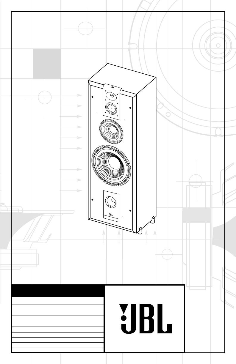
OWNER’S GUIDE
PRODUCT LINE:
MODEL
NUMBER:
DESIGN GOAL: Bring the thrill of live performance and movie sound to
the homeenvironment bycalling on JBL’s professional engineering leadership.
TWEETER TYPE: Pure-titanium dome with EOS™ waveguide
WOOFER TYPE:
CROSSOVER NETWORK:Straight-Line Signal Path™ (SSP)
PORT DESIGN: FreeFlow™ flared
PROFESSIONAL REFERENCE:Studio Monitor
STUDIO SERIES
S412P
Cast-aluminum basket with HeatScape™ motor structure
X + 0 + Y2 0M
HZ
Page 2
READ THIS! Important Safety Precautions!
Antenna Lead-In Wire
Ground Clamp
Antenna Discharge Unit (NEC Section 810-20)
Grounding Conductors (NEC Section 810-21)
Electric Service Equipment
Ground Clamps
Power Service Grounding Electrode System
(NEC Art 250, Part H)
18. Overloading. Do not overload wall
outlets, extension cords, or integral
convenience receptacles, as this can
result in a risk of fire or electric shock.
19. Object and Liquid Entry. Never push
objects of any kind into this product through
openings, as they may touch dangerous
voltage points or short-out parts that could
result in a fire or electric shock. Never spill
liquid of any kind on the product.
20. Servicing. Do not attempt to service this
product yourself, as opening or removing
covers may expose you to dangerous
voltage or other hazards. Refer all servicing
to qualified service personnel.
21. Damage Requiring Service. Unplug this
product from the wall outlet and refer servicing to qualified service personnel under
the following conditions:
a. The power-supply cord or the plug has
been damaged; or
b. Objects have fallen onto, or liquid has
been spilled into, the product; or
c. The product has been exposed to rain or
water; or
d. The product does not operate normally
when following the operating instructions.
Adjust only those controls that are covered
by the operating instructions, as an improper
adjustment of other controls may result in
damage and will often require extensive
work by a qualified technician to restore the
product to its normal operation; or
e. The product has been dropped or
damaged in any way; or
f. The product exhibits a distinct change
in performance – this indicates a need for
service.
22. Replacement Parts. When replacement
parts are required, be sure the service
,
technician has used replacement parts
specified by the manufacturer or that have
the same characteristics as the original part.
Unauthorized substitutions may result in fire,
electric shock or other hazards.
23. Safety Check. Upon completion of any
service or repairs to this product, ask the
service technician to perform safety checks
to determine that the product is in proper
operating condition.
24. Wall or Ceiling Mounting. The product
should be mounted to a wall or ceiling only
as recommended by the manufacturer.
25. Heat. The product should be situated
away from heat sources such as radiators,
heat registers, stoves, or other products
(including amplifiers) that produce heat.
Part No. JBLULB 6/96
CAUTION
RISK OF ELECTRIC SHOCK
DO NOT OPEN
CAUTION: To prevent electric shock,
do not remove the grounding plug
on the power cord, or use any plug
or extension cord that does not have
a grounding plug provided.
Make certain that the
AC outlet is properly grounded.
Do not use an adapter plug
with this product.
The lightning flash with arrowhead
symbol, within an equilateral triangle, is
intended to alert the user to the
presence of uninsulated “dangerous
voltage” within the product’s enclosure
that may be of sufficient magnitude to
constitute a risk of electric shock to
persons.
The exclamation point within an
equilateral triangle is intended to alert
the user to the presence of important
operating and maintenance (servicing)
instructions in the literature
accompanying the appliance.
1. Read Instructions. All the safety and
operating instructions should be read before
the product is operated.
2. Retain Instructions. The safety and
operating instructions should be retained
for future reference.
3. Heed Warnings. All warnings on the
product and in the operating instructions
should be adhered to.
4. Follow Instructions. All operating and use
instructions should be followed.
5. Cleaning. Unplug this product from the
wall outlet before cleaning. Do not use
liquid cleaners or aerosol cleaners. Use a
damp cloth for cleaning.
6. Attachments. Do not use attachments not
recommended by the product manufacturer,
as they may cause hazards.
7. Water and Moisture. Do not use this
product near water – for example, near a
bathtub, wash bowl, kitchen sink or laundry
tub; in a wet basement; or near a swimming
pool; and the like.
8. Accessories. Do not place this product on
an unstable cart, stand, tripod, bracket, or
table. The product may fall, causing serious
injury to a child or adult, and serious
damage to the product. Use only with a cart,
stand, tripod, bracket, or table recommended
by the manufacturer, or sold with the
product. Any mounting of the product should
follow the manufacturer’s instructions, and
should use a mounting accessory
recommended by the manufacturer.
9. A Product and Cart Combination Should
Be Moved with Care. Quick stops, excessive
force, and uneven surfaces may cause the
product and cart combination to overturn.
10. Ventilation. Slots and openings in the
cabinet are provided for ventilation and to
ensure reliable operation of the product and
to protect it from overheating, and these
openings must not be blocked or covered.
The openings should never be blocked by
placing the product on a bed, sofa, rug, or
other similar surface. This product should
not be placed in a built-in installation such
as a bookcase or rack unless proper
ventilation is provided or the manufacturer’s
instructions have been adhered to.
2
11. Power Sources. This product should be
operated only from the type of power source
indicated on the marking label. If you are
not sure of the type of power supply to your
home, consult your product dealer or local
power company. For products intended to
operate from battery power, or other
sources, refer to the operating instructions.
12. Grounding or Polarization. This product
may be equipped with a polarized alternating-current line plug (a plug having one
blade wider than the other). This plug will fit
into the power outlet only one way. This is a
safety feature. If you are unable to insert the
plug fully into the outlet, try reversing the
plug. If the plug should still fail to fit, contact
your electrician to replace your obsolete
outlet. Do not defeat the safety purpose of
the polarized plug.
13. Power-Cord Protection. Power-supply
cords should be routed so that they are not
likely to be walked on or pinched by items
placed upon or against them, paying
particular attention to cords at plugs,
convenience receptacles, and the point
where they exit from the product.
14. Nonuse Periods. The power cord of the
product should be unplugged from the outlet
when left unused for long periods of time.
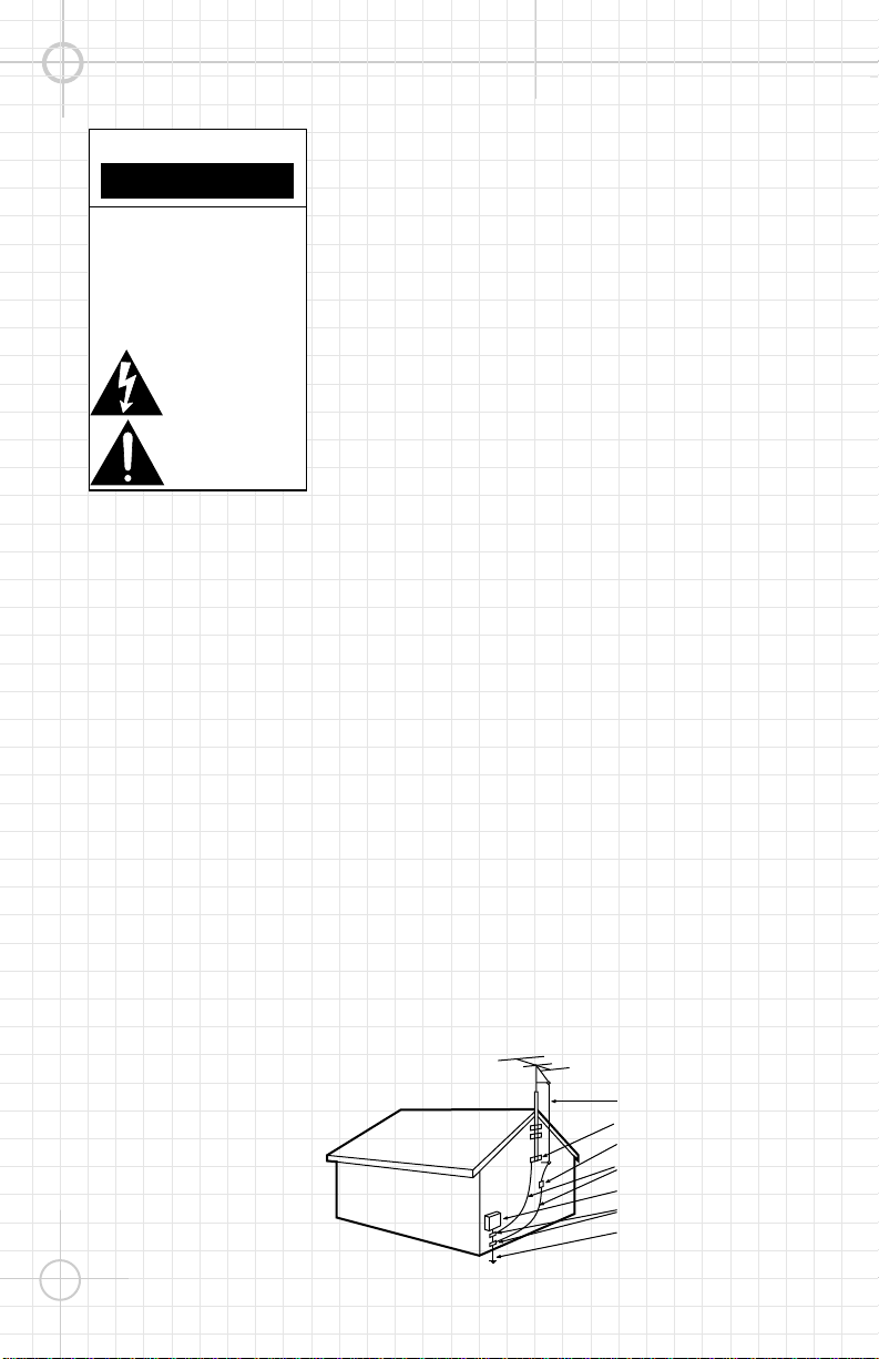
15. Outdoor Antenna Grounding. If an outside
antenna or cable system is connected to the
product, be sure the antenna or cable
system is grounded so as to provide some
protection against voltage surges and builtup static charges. Article 810 of the National
Electrical Code, ANSI/NFPA 70, provides
information with regard to proper grounding
of the mast and supporting structure,
grounding of the lead-in wire to an antenna
discharge unit, size of grounding conductors
location of antenna-discharge unit,
connection to grounding electrodes, and
requirements for the grounding electrode.
See Figure 1.
16. Lightning. For added protection for this
product during a lightning storm, or when
it is left unattended and unused for long
periods of time, unplug it from the wall outlet
and disconnect the antenna or cable system.
This will prevent damage to the product due
to lightning and power-line surges.
17. Power Lines. An outside antenna system
should not be located in the vicinity of
overhead power lines or other electric light
or power circuits, or where it can fall into
such power lines or circuits. When installing
an outside antenna system, extreme care
should be taken to keep from touching such
power lines or circuits, as contact with them
might be fatal.
Figure 1.
Example of Antenna
Grounding as per National
Electrical Code, ANSI/NFPA 70
Page 3
THANK YOU FOR CHOOSING JBL
Without pad With pad
For more than 50 years,
JBL has been involved in
every aspect of music
and film recording and
reproduction, from live
performances to the
recordings you play in
your home, car or office.
We’re confident that the
JBL loudspeakers you
have chosen will provide
every note of enjoyment
that you expected – and
that when you think about
purchasing additional
audio equipment for
your home, car or office,
you will once again
choose JBL.
Please take a moment to
complete the enclosed
profile card. It enables us
to keep you posted on our
latest advancements, and
helps us to better
understand our customers
and build products that
meet their needs and
expectations.
JBL Consumer Products
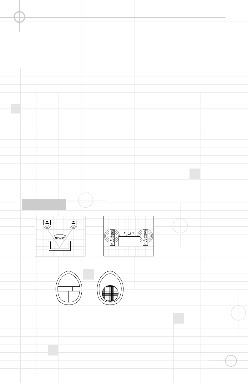
SPEAKER PLACEMENT
Proper placement of the
speakers is an important
step in obtaining the
most realistic soundstage possible. These
recommendations are for
the optimum placement of
the loudspeakers.
Use them as a guide. Slight
variations will not diminish
your listening pleasure.
All of the Studio Series
MODEL:S412P
This model is shipped with
four self-adhesive nonskid
pads that are to be used if
the loudspeaker is placed
on a smooth-surfaced
floor, such as tile or
hardwood. Gently lay the
speaker on its side (not its
front or back) on a soft,
nonabrasive surface.
Attach each pad to the
bottom of its foot in the
widest portion of the
recessed area.
DO NOT attach the pads if
the speaker will be placed
on carpeting.
loudspeakers are videoshielded and can safely be
placed near a television.
drag the speaker
NEVER
to move it, as this will
damage the pads, the feet
and/or the wood cabinet
itself. Always lift the
speaker and carry it to its
new location.
3
Page 4

SPEAKER CONNECTIONS
– +– +
– +
Speaker Outputs
LEFT
RIGHT
– +
CONNECTION TIPS
Speakers and electronics
terminals have corresponding (+) and (–)
terminals. It is important to
connect both speakers
identically: (+) on the
speaker to (+) on the
SPEAKER-LEVEL CONNECTIONS
amplifier and (–) on the
speaker to (–) on the
amplifier. Wiring “out of
phase” results in thin
sound, weak bass and a
poor stereo image.
Your S412P speakers
should be connected to
your receiver in two ways
(at speaker level and line
level) in order to achieve
the best performance,
especially when listening
to program material
recorded in digital 5.1
formats, such as
Dolby** Digital and DTS.
Connect the left-front and
4
right-front speaker
terminals on your receiver
or amplifier to the 5-way
binding posts on the back
of each S412P speaker.
Remember to maintain the
correct polarities (“+” to
“+” and “–” to “–”). The
S412P uses a red binding
post for “+” and black for
®
“–”. These connections
will provide full-range
sound to all four
transducers, and you
should ALWAYS make
these connections.
If your receiver or
amplifier does not have a
line-level subwoofer
output, then you do not
need to make any other
connections, and you
should skip to the section
titled “Amplifier Controls.”
Page 5

RECEIVER/AMPLIFIER
LEFT S412P RIGHT S412P
LEFT
RIGHT
Y-Connector
(not included)
LFE IN LFE IN
SUBWOOFER OUT
LINE-LEVEL CONNECTIONS
Each S412P speaker is also
equipped with a line-level
Low-Frequency Effects
(LFE/Subwoofer) input for
superior performance with
digital 5.1 surround
formats. The .1 LFE
channel contains
additional low-frequency
information not found in
the left- and right-front
channels. The LFE input
works with the full-range
speaker-level input to
provide the dynamics and
effects that your favorite
filmmakers intended.
You will need to use a
Y-Connector (not included)
with one male connector
and two female connectors
to connect the line-level
subwoofer output on your
receiver/amplifier to the
LFE/Subwoofer inputs on
the S412P speakers. Plug
the male connector into
the subwoofer output on
your receiver or amplifier,
and connect each of the
two female connectors
to extension RCA patch
cords. Then plug each
patch cord into the
LFE/Subwoofer input of
the left and right S412P
speakers. Note: If your
receiver has separate
left and right line-level
subwoofer (or LFE) output
jacks, you do not need to
use a Y-Connector.
5
Page 6

AMPLIFIER CONTROLS
MANUAL
LFE LEVEL
Min Max
AUTO
ON
OFF
S412P
LFE IN –
ON
OFF
GREEN “ON”LED
POWER ON/OFF
CAUTION
RISK OF ELECTRIC SHOCK
DO NOT OPEN
“WARNING: TO REDUCE THE RISK OF FIRE OR ELECTRIC SHOCK,
DO NOT EXPOSE THIS APPLIANCE TO RAIN OR MOISTURE.”
“AVERTISSEMENT: POUR PRÉVENIR LES RISQUES D’INCENDIE OU
DE CHOC ELECTRIQUE, EVITER D’EXPOSER CET APPAREIL A LA
PLUIE OU A L’HUMIDITE.”
This area is designed to become quite warm
during normal operation.
LFE Level Control: Allows
you to adjust the volume of
the low-frequency effects/
subwoofer channel to suit
your room acoustics or
tastes. However, it only
affects the LFE signal. If
you are not using the LFE
input, the LFE level control
will not operate.
Configuring Your Receiver:
You should choose the
“Large” or “Wide” option
for the left- and right-front
speakers so that full lowfrequency information will
be sent to the S412P
speakers. Make sure that
you also configure your
receiver for “Subwoofer
On” or “LFE On.” In this
case, the LFE/Subwoofer
signal will
consist only of
the .1 (bass)
LFE signal level can be
adjusted by using the
LFE level on the S412P
amplifier panel. For initial
setup, you should set the
level controls on both
speakers at minimum
(full counterclockwise
rotation). With 5.1 source
material playing, advance
the level controls on each
speaker slowly until the
desired amount of effects
channel is present. This
is a rather subjective
adjustment and should be
made using a variety of
program materials.
If you choose, you can use
the “Small” or “Narrow”
setting on your receiver.
In this case, all of the
information below 80Hz
will be fed to the LFE/
Subwoofer input on the
6
channel. The
S412P. Now the level
control operates throughout the entire bass
spectrum below 80Hz, not
just within the .1 channel
portion. This configuration is
generally unnecessary but,
in certain room-placement
conditions, it allows greater
bass-level control.
Power Switches: The main
“Power” switch is simply
marked “On” and “Off.”
Turn this switch on to
commence operation of
the powered amplifier
after you have plugged the
power cord into an AC
outlet. The second switch
is labeled “On/Off” and
has two positions. Placing
the switch in the “Auto”
position puts the amplifier
in Standby mode. In this
mode the speaker will be
able to automatically
sense an incoming signal,
which will trigger it to turn
fully on. The speaker will
also automatically switch
itself back into Standby
mode after approximately
10 to 15 minutes have
passed without its sensing
a signal. We recommend
that you leave this switch
in the “Auto” position for
most applications. If you
will be away from home or
not using your speakers
for an extended period of
time, you should turn the
speakers off by using the
main power switch. The
Manual position will bypass
the auto-sensing feature
and leave the amplifier on
until turned off with the
main switch or returned to
auto sensing by choosing
the auto position.
LED Indicators: When your
speaker is turned on but is
not receiving a signal, the
LEDs glow red to let you
know that your speaker is
plugged in. When the
speaker is receiving a
signal, the LEDs glow
green. We have provided a
convenient “Green ‘On’
LED” switch on the back
panel to allow you to shut
off the front LEDs should
they interfere with your
enjoyment of a movie. This
switch has no effect when
the LEDs are in red mode.
Page 7

TROUBLESHOOTING
If there is no sound from
any of the speakers:
• Check that receiver/
amplifier is on and that a
source is playing.
• Review proper operation
of your receiver/amplifier.
If there is no sound coming
from one speaker:
• Check the “Balance”
control on your
receiver/amplifier.
• Check all wires and
connections between
receiver/amplifier
and speakers.
• Make sure all wires are
connected. Make sure
none of the speaker wires
are frayed, cut or
punctured.
If the system plays at low
volumes but shuts off as
volume is increased:
• Check all wires and
connections between
receiver/amplifier
and speakers.
• Make sure all wires are
connected. Make sure
none of the speaker
wires are frayed, cut or
punctured.
• If more than one pair of
main speakers is being
used, check the minimum
impedance requirements of
your receiver/amplifier.
If there is no (or low) bass
output:
• Make sure the polarities
(+ and –) of the left and
right “Speaker Inputs” are
connected properly.
• Make sure that the
speaker is plugged into an
active electrical outlet and
switched on, and that the
green LEDs are displayed.
If you used the LFE input
and there is no sound from
the subwoofer:
• Check that receiver/
amplifier is on and that a
source is playing.
• Make sure that the
speaker is plugged into an
active electrical outlet.
• Check all wires and
connections between
receiver/amplifier and
speakers.
• Make sure all wires are
connected. Review the
“Line-Level Connections”
section on page 5 of this
manual and make sure that
a single RCA patch cord
is connected to each
loudspeaker from the
Y-Connector plugged into
the receiver/amplifier’s
subwoofer output. Make
sure none of the speaker
wires are frayed, cut or
punctured.
• Review proper operation
of your receiver/amplifier,
including making sure that
you have configured your
receiver so that the subwoofer output is active.
If you are using the S412P
LFE/Subwoofer input and
the bass level decreases
(instead of increasing)
when you turn the LFE/
Subwoofer Level knob
clockwise:
• Recheck to make sure
that your receiver or
amplifier-speaker outputs
are correctly connected to
the S412P speaker inputs
(gold-plated binding posts),
(+) to (+) and (–) to (–). The
S412P (+) terminal has a red
stripe and is located on the
right-hand side, below the
letter “L” of the molded JBL
logo, when looking directly at
the back of the S412P.
• If the wires are connected
properly, the confusion may
be attributable to the design
of your receiver/ amplifier.
Your unit may have inverting
inputs, which reverse the
polarity of the signal
between the inputs and
outputs of the amplifier. To
check if this is the case,
reverse the speaker connections for ALL S412Ps in
your system (and disconnect
any other
system) so that the
receiver/amplifier’s (+)
connector is connected to
each S412P’s (–) (black
stripe) speaker connector.
If you do this and the
S412Ps function properly
(bass increases as you turn
your LFE/Subwoofer levelcontrol knobs clockwise),
your receiver/amp uses
inverting inputs. This is not
a problem. Simply connect
all of the speakers in your
system the same way, with
the receiver or amplifier’s
(+) terminal to the speaker’s
(–) terminal, and the receiver
or amplifier’s (–) terminal to
the speaker’s (+) terminal.
speakers in the
7
Page 8

SPECIFICATIONS
S412P
Maximum Recommended Amplifier Power*: 250W
Powered Subwoofer Amplifier Output: 200W
Nominal Impedance: 8 Ohms
Sensitivity (2.83V/1m): 91dB
Frequency Response (–3dB): 32Hz – 20kHz
Crossover Frequencies: 200Hz, 850Hz, 3500Hz
High-Frequency Transducer: 1" Pure-titanium dome
Midrange Transducer: 4" PolyPlas™ cone
Midbass Transducer: 6" PolyPlas™ cone
Low-Frequency Transducer: 12" PolyPlas™ cone
Dimensions (H x W x D): 44" x 16" x 13-3/8" (1118mm x 406mm x 340mm)
Weight (per speaker): 86 lb (39.1 kg)
*The maximum recommended amplifier power rating will ensure proper system headroom to
allow for occasional peaks. We do not recommend sustained operation at these maximum
power levels.
Occasional refinements may be made to existing products without notice but will always meet
or exceed original specifications, unless otherwise stated.
**Trademark of Dolby Laboratories.
DTS is a registered trademark of Digital Theater Systems, Inc.
OWNER’S GUIDE
PRODUCT LINE:
MODEL
NUMBER:
DESIGN GOAL: Bring the thrill of live performance and movie sound to
the homeenvironment bycalling on JBL’s professional engineering leadership.
TWEETER TYPE: Pure-titanium dome with EOS™ waveguide
WOOFER TYPE:
CROSSOVER NETWORK: Straight-Line Signal Path™ (SSP)
PORT DESIGN: FreeFlow™ flared
PROFESSIONAL REFERENCE: Studio Monitor
STUDIO SERIES
S412P
Cast-aluminum basket with HeatScape™ motor structure
PRO SOUND
COMES HOME
JBL Consumer Products
250 Crossways Park Drive, Woodbury, NY 11797
8500 Balboa Boulevard, Northridge, CA 91329
800-336-4JBL (4525) (USA only)
www.jbl.com
©1999 JBL, Incorporated.
JBL is a registered trademark of JBL, Incorporated.
Part No.
S412P O/G
™
 Loading...