

Page 1
S36IIPM
STUDIO™SERIES
OWNER’S GUIDE
For more than 50 years, JBL has
been involved in every aspect of
music and film recording and
reproduction, from live performances to the recordings you play
in your home, car or office.
We’re confident that the JBL loudspeakers you have chosen will
provide every note of enjoyment that
you expected – and that when you
think about purchasing additional
audio equipment for your home, car
or office, you will once again
choose JBL.
Please take a moment to register
your product at our Web site,
www.jbl.com. It enables us to keep
you posted on our latest advance-
ments, and helps us to better
understand our customers and
build products that meet their
needs and expectations.
JBL Consumer Products
THANK YOU FOR CHOOSING JBL
Page 2
SPEAKER PLACEMENT
Proper placement of the speakers
is an important step in obtaining the
most realistic soundstage possible.
These recommendations are for the
optimal placement of the loudspeakers. Use these placement
recommendations as a guide. Slight
variations will not diminish your listening pleasure.
The Studio
™
Series S36IIPM loudspeakers are video-shielded and
can safely be placed near a
television.
The loudspeakers are weatherresistant and may be used either
indoors or outdoors, such as in a
patio area. As noted below, when
using the speakers outdoors, we
recommend mounting them under
an overhang, such as roof eaves,
for added protection. Because
they are resistant to moisture,
the speakers are also appropriate
for mounting in a bathroom,
although not inside a bathtub or
shower stall.
Although these loudspeakers are
designed as a mirrored pair, the
decision as to which one is left or
right will depend on the amount of
space left between them.
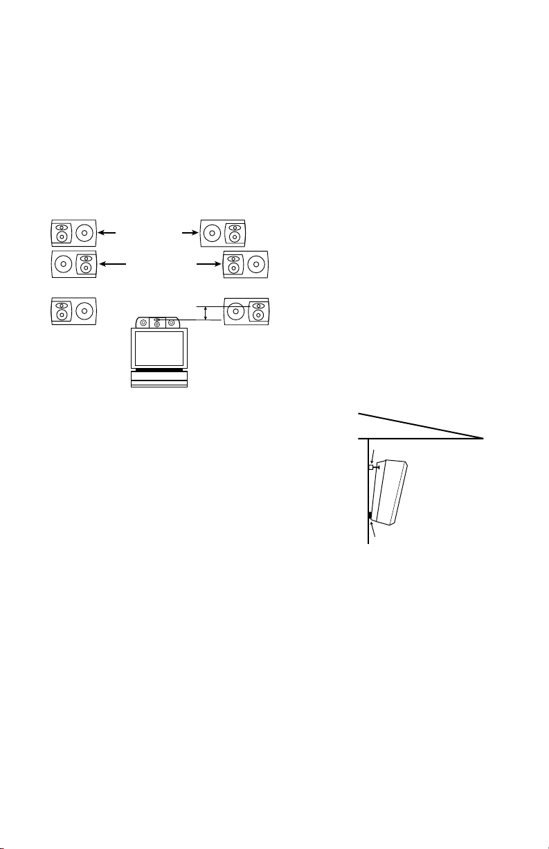
A wider stereo image is presented
with the tweeter/midrange array
outboard, and a tighter image is
presented with the array inboard.
For stereo-only applications:
For home theater applications:
This placement provides a wide
spread in sound, supplemented
by the center channel speaker.
Do not attempt to mount these
speakers on a ceiling, on the
underside of roof eaves or in a
shower stall.
The S36IIPM loudspeakers may be
positioned on the wall either horizontally or vertically. The grille logo
on each speaker may be rotated
depending on how the speaker is
positioned. Gently pull the logo
away from the grille slightly, rotate it
to the desired position, and let go.
The logo will snap back into place.
When mounted vertically, the
tweeter array may be positioned
either up or down, depending on the
height of the placement. If the
speakers will be above ear level,
the tweeter array should be positioned down, preferably no more
than two feet above ear level. If
the speakers will be mounted very
low, it may be best to position the
tweeter array upward so that it will
be no more than two feet below
ear level.
The enclosures are specially
designed to angle the speakers
toward the listener when mounted
flush against the wall.
When mounting the speakers outdoors, we recommend that you
place them under an overhang,
such as roof eaves, for added protection, and that you use two of
the supplied special angle-mount
screws per speaker, which angle
the speakers downward at a
greater-than-usual angle, facilitating water drainage.
NOTE: When using the enclosed
angle-mount screws, always use
the top two screw locations appropriate for the specific mounting
orientation of your S36
IIPM.
Referring to the enclosed installation template, screw locations (1)
and (2) are to be used when
mounting the S36
IIPM horizontally
so that these locations are on top.
To mount the loudspeakers vertically, use locations (2) and (4)
or
locations (1) and (3), depending on
the mounting orientation. Do not
mount the speaker upside down
(with screw locations (3) and (4) on
top) because it won’t be able to
lock onto the screw heads.
Remember that the JBL logo on
the tweeter/mid faceplate can be
rotated with choice of speaker
position (vertical or horizontal).
At least one screw per speaker
should be installed in a wooden
wall stud. Select an appropriate
wall anchor for the other screw.
If the special angle-mount screws
are not being used, size 10 screws
of at least 1-1/2" in length are recommended. If the screws are used
in drywall or other surfaces incapable of holding the screw by
itself, selection of proper anchors
is essential. The customer is solely
responsible for proper selection
and installation of screws, anchors
and other installation hardware.
Further installation details are
included on the installation
template.
WALL-MOUNTING
0-2 ft.
Less than 6 – 8 feet
More than 6 – 8 feet
Roof eave
Supplied Angle-Mount Screw
(When using angle-mount screws,
always utilize the top
two screw holes on the
S36IIPM, depending on
mounting orientation.)
PM
II
Wall
Horizontal mounting:
S36
Use screwholes (1) and (2).
Vertical mounting: Use
screwholes (1) and (3), or (2)
and (4), whichever are uppermost.
Supplied Rubber Pad
Page 3

If there is no sound from any of the
speakers:
• Check that receiver/amplifier is
on and that a source is playing.
• Review proper operation of your
receiver/amplifier.
• Make sure all wires are connected. Make sure none of the
speaker wires are frayed, cut or
punctured, or touching each other.
If the system plays at low volumes
but shuts off as volume is
increased:
• Check all wires and connections
between receiver/amplifier and
speakers.
• Make sure all wires are connected. Make sure none of the
speaker wires are frayed, cut or
punctured, or touching each other.
• If more than one pair of main
speakers is being used, check the
minimum impedance requirements
of your receiver/amplifier.
If there is no sound coming from
one speaker:
• Check the “Balance” control on
your receiver/amplifier.
• Check all wires and connections
between receiver/amplifier and
speakers. Make sure no wires are
touching other wires or terminals
and creating a short circuit.
• Make sure all wires are connected. Make sure none of the
speaker wires are frayed, cut or
punctured.
• In Dolby* Digital or DTS
®
modes,
make sure that the receiver/
processor is configured so that the
speaker in question is enabled.
• Turn off all electronics and switch
the speaker in question with one of
the other speakers that is working
correctly. Turn everything back on,
and determine whether the problem has followed the speaker, or
has remained in the same channel.
If the problem is in the same channel, the source of the problem is
most likely with your receiver or
amplifier, and
you should consult the
owner’s manual for that product for
further information.
If the problem
has followed the speaker, consult
your dealer for further assistance
or, if that is not possible, visit
www.jbl.com for further information.
CONNECTION TIPS
SPEAKER CONNECTIONS
Speakers and electronics terminals
have corresponding (+) and (–) terminals. It is important to connect
both speakers identically: (+) on the
speaker to (+) on the amplifier and
(–) on the speaker to (–) on the
amplifier. Wiring “out of phase”
results in thin sound, weak bass
and a poor stereo image. With the
advent of multichannel surround
TROUBLESHOOTING
– +– +
– +
Speaker Outputs
LEFT
RIGHT
– +
Installation of Self-Adhesive
Rubber Pads: If the speaker is to
be placed on a surface (such as
a table top or shelf) rather than
wall-mounted, the enclosed selfadhesive rubber pads are to be
attached to the bottom of the
speaker cabinet in their designated recessed locations. If the
speaker is to be wall-mounted,
then the four self-adhesive rubber
pads should be attached to the
back of the speaker, as shown in
the bottom right diagram.
When angle-mounting the
S36
IIPM, only two of the rubber
pads are required, and they need
to be installed on the back of the
loudspeaker, near the lower edge,
so that they are located between
the back of the speaker and the
mounting surface. Please see the
enclosed installation template for
more details.
NOTE: The threaded inserts on the
bottom of the speakers are to be
used only with JBL accessories
that have been developed specifically for the S36
II
PM and that may
become available at a future date.
Do not attempt to install bolts or
any non-JBL brackets or acces-
sories to these threads, as this
might damage the speaker and
dislodge the insert.
PADS GO HERE
sound systems, connecting all of
the speakers in your system with
the correct polarity remains
equally important in order to preserve the proper ambience and
directionality of the program
material.
To use the binding-post speaker
terminals, unscrew the collar until
the pass-through hole in the center post is visible under the collar.
Insert the bare end of the wire
through this hole; then screw the
collar down until the connection
is tight.
The hole in the center of each collar is intended for use with bananatype connectors.
To comply with
KEYHOLES FOR
MOUNTING HARDWARE
PLACE RUBBER PADS HERE
For wall-mounting
For tabletop or shelf placement
European CE certification, these
holes are blocked with plastic
inserts at the point of manufacture.
Use of banana-type connectors
requires the removal of the inserts.
Do not remove these inserts if
you are using the product in an
area covered by European CE
certification.
Page 4

12
SPECIFICATIONS
DESIGN GOAL: Bring the thrill of live performance and movie sound to the
homeenvironment bycalling on JBL’s professional engineering leadership.
TWEETER TYPE: Pure-titanium dome with EOS™ waveguide
WOOFER TYPE: Cast-aluminum basket with HeatScape™ motor structure
CROSSOVER NETWORK: Straight-Line Signal Path™ (SSP)
ENCLOSURE DESIGN: Sealed
PROFESSIONAL REFERENCE: Studio Monitor
OWNER’S GUIDE
PRODUCT LINE:
MODEL:
S36IIPM
STUDIO
™
SERIES
© 2003 Harman International Industries, Incorporated
JBL is a registered trademark of
Harman International Industries, Incorporated.
Part No.
406-000-05000
PRO SOUND
COMES HOME
™
JBL Consumer Products
250 Crossways Park Drive, Woodbury, NY11797
8500 Balboa Boulevard, Northridge, CA 91329
800.336.4JBL (4525) (USA only)
www.jbl.com
S36IIPM
Description: 3-Way 6" horizontal/vertical mirror-image wall-mount/bookshelf loudspeakers for indoor and
outdoor use
Maximum Recommended Amplifier Power:**150W
Nominal Impedance: 8 Ohms
Sensitivity (2.83V/1m):
90dB
Frequency Response (–3dB):
60Hz – 20kHz
Crossover Frequencies: 650Hz, 3000Hz
High-Frequency Transducer:1" Pure-titanium dome, with rubber surround, shielded; Elliptical Oblate
Spheroidal™ (EOS) waveguide
Midrange Transducer:4" WeatherPlas™ (polymer-coated cellulose fiber) cone, rubber surround, shielded;
Linear Field Proximity™ (LFP) bezel
Low-Frequency Transducer
: 6" WeatherPlas™ (polymer-coated cellulose fiber) cone, rubber surround,
SFG™, magnetic shorting rings, high-temp oversized Kapton®voice coil, HeatScape™ motor structure,
cast-aluminum baskets, shielded
Baffles: Low diffraction, IsoPower™
Enclosure: Sealed
Network: Straight-Line Signal Path™ (SSP)
Terminals:All-metal, gold-plated, 5-way binding posts
Dimensions (H x W x D): 10-1/4" x 14-5/8" x 5" (260mm x 371mm x 127mm)
Weight: 11 lb/5kg
We, Harman Consumer International
2, route de Tours
72500 Chateau-du-Loir
France
declare in own responsibility that the loudspeakers described in this owner’s manual
are in compliance with technical standards:
EN 50081-1:1992
EN 50082-1:1997
Gary Mardell
Harman Consumer International
Chateau-du-Loir, France 2/03
* Dolby is a trademark of Dolby Laboratories.
DTS is a registered trademark of Digital Theater Systems, Inc.
**The maximum recommended amplifier power rating will ensure
proper system headroom to allow for occasional peaks. We do not
recommend sustained operation at these maximum power levels.
All features and specifications are subject to change without
notice.
Declaration of Conformity
 Loading...