


MR SERIES
LOUDSPEAKERS
OWNER’S
MANUAL
M5
MR25
MR26
MR28
MR38
MR308II
MR
MR310II
SERIES
MR Center
INTRODUCTION
40°-60°
Congratulations on choosing JBL MR
Series Loudspeakers. Their highly
accurate, uncolored and balanced
sound character will greatly increase
your enjoyment of recorded music
and movies. JBL speakers are built
with careful attention to detail, using
only the highest quality materials.
They will provide many years of
excellent performance.
The MR Series is the result of combining traditional JBL Signature
Sound performance values with elegant contemporary appearance.
between them, at the listening position, is between 40 and 60 degrees
(see Fig. 1). For example, if your listening position is 8 to 12 feet (2.5m
to 4m) from each speaker, the two
systems should be about 8 feet
(2.5m) apart. Placing the loudspeakers in corners or against a wall will
result in the strongest (not necessarily the most accurate) bass. Except
for the M5, all MR Series speakers
have their ports in the front so you
can place the rear of the speaker up
against a wall. In the case of the M5,
do not place the speaker closer than
3 inches (75mm) to the wall behind it
if possible.
Maximum Radiating Surface Area:
MR Series transducers utilize new
transducer technology by extending
the surface area of the cone allowing for a shorter excursion of the
driver without sacrificing critical air
movement.
Maximum Efficiency: Larger air
movement coupled with shorter coil
movement allows the MR transducers
to be very efficient. See specifications.
Maximum Transducer Control:
Reduces distortion by tightening
the control of driver excursion and
increasing driver linearity.
Smooth, Accurate, Extended
Response: The MR series trans-
ducers, computer-optimized dividing
networks, and bass reflex cabinets
combine to give clear, crisp, accurate, JBL Signature Sound.
PLACEMENT
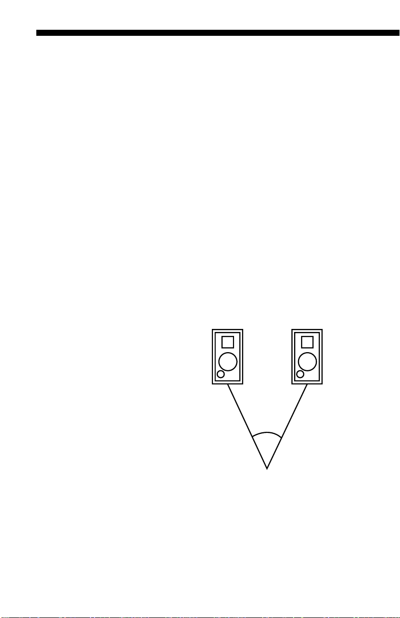
Bookshelf Models: For the best
stereo reproduction, the two loudspeaker systems should be an equal
distance from your listening position
and separated so that the angle
For the best stereo imaging, we recommend that the systems be placed
so that the high frequency transducers are positioned approximately at
ear level of a seated listener. Every
room is different and there are different tastes, so don’t hesitate to experiment on your own.
Fig. 1
Tower Models: The Tower models
cabinet height and driver placement
allow for speaker placement directly
on the floor. For the best stereo
reproduction, the two loudspeaker
systems should be an equal distance
from your listening position and separated so that the angle between
2
MR SERIES LOUDSPEAKERS
(2 ft. or less)
(2 ft. or less)
them, at the listening position, is
between 40 and 60 degrees. For
example, if your listening position is
8 to 12 feet (2.5m to 4m) from each
speaker, the two systems should be
about 8 feet (2.5m) apart.
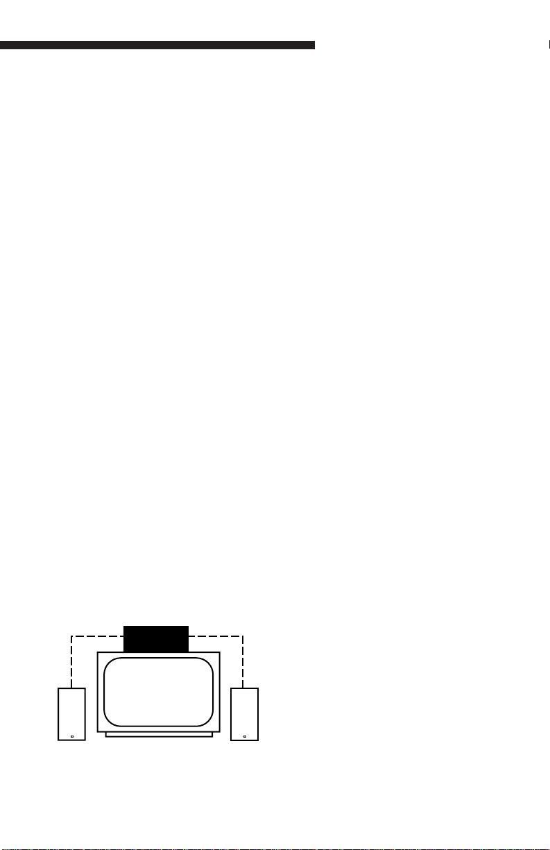
Center Channel Model: As the
center channel contains the dialog
and other central action sounds, the
speaker should be located very close
to the Monitor/TV and centered with
the Monitor/TV’s center line. Place
the MR Center directly on top of or
directly below the Monitor/TV with the
front edge of the speaker grille flush
with the edge of the Monitor/TV. You
should have your Left and Right
speakers within a 2 ft or less height
range of your Center Channel for
proper sonic performance (see Fig 2).
In Case Color Interference Occurs:
The speaker is shielded to work with
video applications, however some
color interference may be observed
on the TV screen depending on the
type of your TV set. If color interference is observed, turn your TV off for
15 minutes and move the speaker
back about 1" from the front edge of
the TV. Turn on TV and recheck. If
this is not far enough, move back further and experiment until the interference disappears. You may have to
turn the TV off for a few minutes and
turn it on again to clear the screen.
Fig. 2
CONNECTIONS
To connect the loudspeaker systems
to the receiver or amplifier, use twoconductor insulated wire. Your JBL
dealer can recommend suitable
cables, or you can buy wire at most
hardware or electronic stores. We
recommend #16 AWG wire as a minimum size. If your speaker is more
than 30 feet (10m) from your receiver
or amplifier, use larger diameter
lower gauge wire. Connections are
made at the terminals located on the
back of the MR Series speakers.
Preparing the Hookup Wire
Carefully plan your wire lengths
before cutting any speaker wire.
Be sure to allow plenty of extra
wire to help hide paths in corners,
along baseboards, etc.
1. For Left and Right Speakers, first
determine the wire length needed
between the most distant speaker
and the receiver or amplifier.
2. Now make the hookup wires for
both speakers this length, even if one
loudspeaker is much closer to your
amplifier than the other. This will
help maintain proper signal balance.
(For the MR Center, determine the
length needed from AV receiver’s
center channel output to speaker).
3. Strip off 3⁄8" of insulation from both
ends of each conductor.
4. Twist each set of thin wires into a
tightly-bunched spiral.
5. At this point you need to identify a
visual difference between the two
conductors of each molded pair of
speaker wire. Differentiating marks
can be a different color wire (copper
or “silver”); a strand of yarn in one
conductor; thin, raised ribs on one
3
part of the outer insulation; or a print-
Left
Speaker
Amplifier/Receiver
Right
Speaker
Red Blk.
(+)
++
(–)
RedRLBlk.
(+) (–)
ed “+” marking on one of the insulators. It does not make any difference
which of the two strands of wire go to
(+) and (–) on the speakers and
amplifier, as long as all speakers
used in your system are connected
identically. Push down on the button
below the terminal and insert the wire
through the hole.
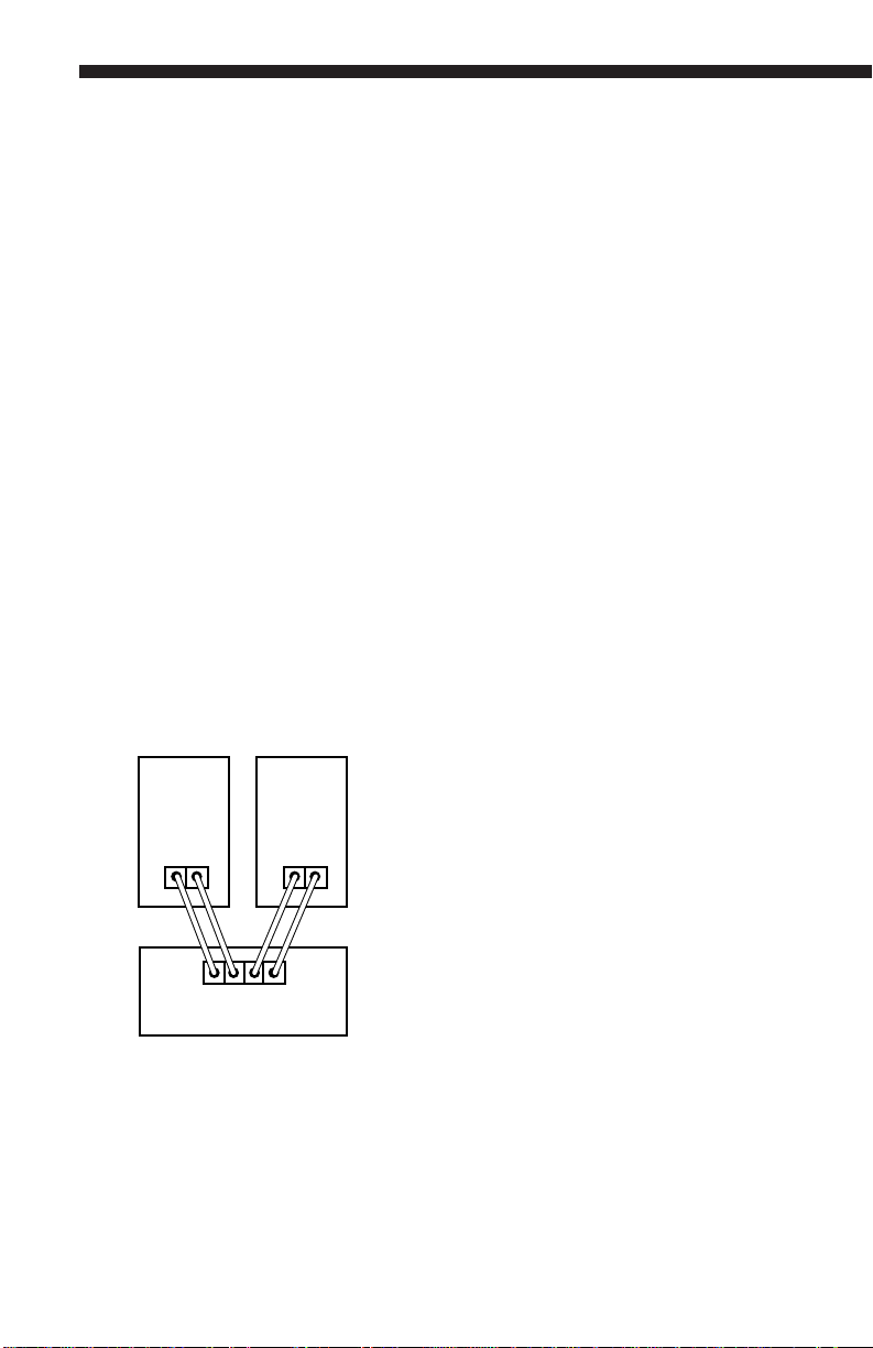
For each channel, the red terminal on
all loudspeakers should be connected
to the red or (+) speaker connection
terminal on the receiver or amplifier,
and the black to black or (–) speaker
connection terminal (see Fig. 3).
Connecting the loudspeakers in this
manner ensures that they will be in
phase; that is, work together rather
than in opposition. This is very
important when connecting several speakers together in a Dolby
Pro-Logic AV application. Connecting
the loudspeakers out of phase will
not damage them, but will result in
less bass and poor imaging.
Fig. 3
AV receiver will enable you to correctly balance the level (volume) of
sound coming from each speaker in
your Dolby Pro-Logic application.
Hooking Up Multiple Sets
of Speakers
If your receiver has two complete
sets of speaker terminals (“A” and
“B”), it’s possible to hook up an additional pair of speakers for
ous
sound in another room. However,
simultane-
some speakers may not be usable as
a second pair if you want to play two
sets at once. Before hooking up
another set of speakers besides your
MR Series loudspeakers, check the
following:
1. Your amplifier’s minimum load
impedance.
2. The nominal impedance of the
second set of speakers. Both of
these specifications are expressed in
ohms and both can be found in the
owner’s manuals which came with
your speakers and amp/receiver. The
receiver’s minimum load impedance
is determined by whether or not
power ratings are given for 4 ohms.
This is because two sets of 8 ohm
speakers will present a 4 ohm load to
the receiver. The MR speaker, when
combined with an 8 ohm speaker,
produces an impedance sufficiently
close to 4 ohms. For example, the
following entry in an amplifier owner’s
manual...
When connecting the MR Center or
other MR Series speakers to a Dolby
Pro-Logic AV receiver, refer to the
instructions accompanying your AV
component for use of the “test tone”
to properly balance the sound output
from each speaker. The use of the
“test tone” and the controls on your
4
POWER:
A)100 watts RMS into 8 ohms, both channels driven, 20-20kHz with less than
0.02%THD
B) 160 watts RMS into 4 ohms, both
channels driven, 20-20kHz with less than
0.02% THD.
Part B indicates that the amplifier can
handle 4-ohm combined impedances
created by two sets of speakers.

MR SERIES LOUDSPEAKERS
If only an 8-ohm rating is given, the
amp/receiver may or may not be
designed to handle 4-ohm combined
ratings. Consult the owner’s manual
of the amp/receiver for clarification.
POWER HANDLING
Thanks to their high efficiency, the
JBL MR Series Loudspeakers will
produce reasonable volume levels in
a room of moderate size with very little amplifier power. However, using a
small amplifier to obtain the desired
volume listening levels may lead to
overdriving the amplifier. This will
generate high distortion levels and
may cause damage to your loudspeaker. For the best performance,
an amplifier should be selected with
an output rating that is greater than
the maximum power that will be
used. This margin of reserve power
will ensure that the amplifier will not
attempt to deliver more power than
its design allows. However, the
amplifier’s power rating per channel
must not exceed the maximum recommended amplifier power for that
specific loudspeaker model. Please
see the specification section for
details. Following these guidelines
will provide virtually distortion-free
sound reproduction and long loudspeaker life.
TROUBLESHOOTING
The vast majority of new speaker
“malfunctions” end up being traced to
connections or switch settings. To
avoid packing up correctly functioning
speakers and sending them off, only
to find that they’re not really at fault,
check the following tips first, before
requesting service.
No sound at all or very faint sound
from both speakers
1. Amp/receiver tape monitor button
pushed in while using CD, FM or
phono inputs.
2. Wrong speaker switch, “A” or “B”
speaker output.
3. Sound source (CD,cassette deck,
turntable) not turned on, not activated, not hooked up or not selected on
amp/receiver front panel.
No sound from one speaker
1. Balance control turned all the way
left or right.
2. Speaker wire has become disconnected.
3. One of the connections between
sound source and amp/receiver is
faulty or has become disconnected.
Both speakers play at low volumes
but shut off as volume is increased OR sound turns on and
off intermittently
A few strands of speaker wire may
be shorting out. Recheck the connections. Recheck the impedance of
the amp.
Bass is very weak AND/OR sound
seems to come from each speaker
separately, without creating a
stable stereo image between the
speakers.
1. The polarity (+ & –) of one speaker
has been reversed relative to the
other. Double check connections.
2. Speakers are too far away from
back and side walls or too far apart.
Experiment again with the speaker
placement. If you are still encountering problems, consult your JBL
dealer.
Additional Areas to Check When
Using an AV Receiver:
No sound at all or very faint sound
from the center channel or other
speakers
1. Speaker wire has become disconnected.
5

2. One of the connections between
sound source and AV receiver/amp is
faulty or has become disconnected.
3. AV receiver/amp center channel
mode not selected. Please select a
mode that activates the center
channel.
4. Rear/surround information may not
be recorded in some scenes and
passages.
5. AV receiver/amp “audio direct”
switch is activated. This switch
should be off to activate the 5
speaker surround mode.
6. Sound source (VDP, VCR, CD,
cassette deck, turntable) not turned
on, not activated, not hooked up or
not selected on AV receiver/amp
front panel.
GENERAL CARE
The grille is held in place by pins
near the edges. To remove the grille,
grasp it by both top and bottom
edges and pull gently. To replace
grille, re-position it carefully and
press gently at the corners. Do not
push on the center area of the grille.
NOTE: The M5 grille is nonremovable. Do not attempt to pry
the grille from the cabinet as this
will void your warranty. The rear
panels are removable to allow service personnel access to the driver
components if needed.
SERVICE
Should your loudspeaker ever need
service, return it to the JBL dealer
from whom it was purchased.
If purchased outside the United
States, contact your local distributor
to make arrangements for repair
service. Do not return products to
the JBL factory without prior
authorization.
The loudspeaker cabinet may be
cleaned with a slightly damp cloth. To
remove dust from the grille cloth, use
a vacuum with a brush attachment.
Spots may be removed with a commercial spot remover. Do not use any
cleaners or solvents on the speaker
drivers themselves.
6

MR SERIES LOUDSPEAKERS
Specifications MR Center M5 MR25 MR26
Application Center Bookshelf Bookshelf Bookshelf
Channel
High Frequency 10mm Ti 2" Paper 10mm Ti 10mm Ti
Dome Transducer Composite (Cone) Composite Composite
Midrange Transducer n/a n/a n/a n/a
(Nitrile Polymer Fibre Cone)
Low Frequency Transducer 2 x 3.5" 5" 5" 6
(Nitrile Polymer Fibre Cone) (Neo Magnet)
Crossover Frequency 4.5kHz 2.2kHz 4.5kHz 4.5kHz
Frequency 80 Hz to 75 Hz to 70 Hz to 55 Hz to
Response (– 6 dB) 20 kHz 20 kHz 20 kHz 20 kHz
Sensitivity (1 Watt/1 Meter) 87 dB 86 dB 87 dB 88 dB
Nominal Impedance 8 ohms 8 ohms 8 ohms 8 ohms
Recommended 10 to 80 10 to 50 10 to 75 10 to 100
Amplifier Power* Watts Watts Watts Watts
1
⁄2"
External Dimensions
Height 5
Width 14
Depth 6
3
⁄16" 11" 12" 15"
1
⁄4"6
5
⁄8"7
1
⁄2"7
1
⁄4"8
1
⁄2"8
1
⁄2" 10"
1
⁄2"
External Dimensions
Height 132 mm 280 mm 305 mm 381 mm
Width 362 mm 165 mm 190 mm 216 mm
Depth 168 mm 184 mm 216 mm 254 mm
Weight (each) 7 lbs 7 lbs 8 lbs 12 lbs
3.2 kg 3.2 kg 3.6 kg 5.5 kg
Shipping Weight 10 lbs 18 lbs 20 lbs 28 lbs
4.5 kg 8.2 kg 9.1 kg 12.7 kg
*The maximum recommended amplifier power rating will insure proper system headroom to allow
for occasional program peaks. We do not recommend sustained operation at these maximum
power Levels.
7

MR SERIES LOUDSPEAKERS
Specifications MR28 MR38 MR308II MR310II
Application Bookshelf Bookshelf Tower Tower
High Frequency 14mm" Ti 14mm Ti 14mm Ti 14mm Ti 14mm Ti
Dome Transducer Composite Composite Composite Composite
Midrange Transducer n/a 6
1
⁄2"6
(Nitrile Polymer Fibre Cone)
Low Frequency Transducer 8" 8" 8" 10"
(Nitrile Polymer Fibre Cone)
Crossover Frequency 3.5kHz 3.5kHz 3.5kHz 3.5kHz
Frequency 50 Hz to 45 Hz to 42 Hz to 40 Hz to
Response (– 6 dB) 20 kHz 20 kHz 20 kHz 20 kHz
Sensitivity (1 Watt/1 Meter) 9 0 d B 92 dB 92 d B 92 d B
Nominal Impedance 8 ohms 8 ohms 8 ohms 8 ohms
Recommended 10 to 125 10 to 150 10 to 150 10 to 175
Amplifier Power* Watts Watts Watts Watts
1
⁄2"6
1
⁄2"
External Dimensions
Height 19
Width 10" 10" 10" 11
1
⁄4" 24" 323⁄16" 36"
3
⁄4"
Depth 10" 12" 12" 12"
External Dimensions
Height 489 mm 610 mm 818mm 915 mm
Width 254 mm 254 mm 254 mm 298 mm
Depth 254 mm 305 mm 305 mm 305 mm
Weight (each) 18 lbs 25 lbs 28 lbs 32 lbs
8.2 kg 11.3 kg 12.7 kg 14.5 kg
Shipping Weight 40 lbs 29 lbs 32 lbs 36 lbs
18.2 kg 13.2 kg 14.5 kg 16.4 kg
*The maximum recommended amplifier power rating will insure proper system headroom
to allow for occasional program peaks. We do not recommend sustained operation at
these maximum power Levels.
JBL continually strives to improve its products. New materials, production methods and design refinements are
introduced into existing models without notice as a routine expression of our design philosophy. For this reason,
JBL MR Series Loudspeakers may differ in some respect from their published specifications and descriptions, but
will always equal or exceed the original specifications unless otherwise stated.
250 Crossways Park Drive, Woodbury, NY 11797
8500 Balboa Blvd., Northridge, CA 91329
A Harman International Company
Part No. 332408-001
Printed in Taiwan
 Loading...