

JBL MA6002, MA6004 Service manual
Marine Models:
MA6002 (2 CHANNEL)
MA6004 (
4 CHANNEL)
Power Amplifiers
Service Manual
JBL Consumer Products
250 Crossways Park Dr.
Woodbury, New York 11797 Rev0 11/06

1
MARINE series MA6002/6004
- CONTENTS -
MA6002/6004 BASIC SPECIFICATIONS .…..…………..1
MA6002 DETAILED SPECIFICATIONS ……………..…..2
MA6004 DETAILED SPECIFICATIONS ….……. ………..3
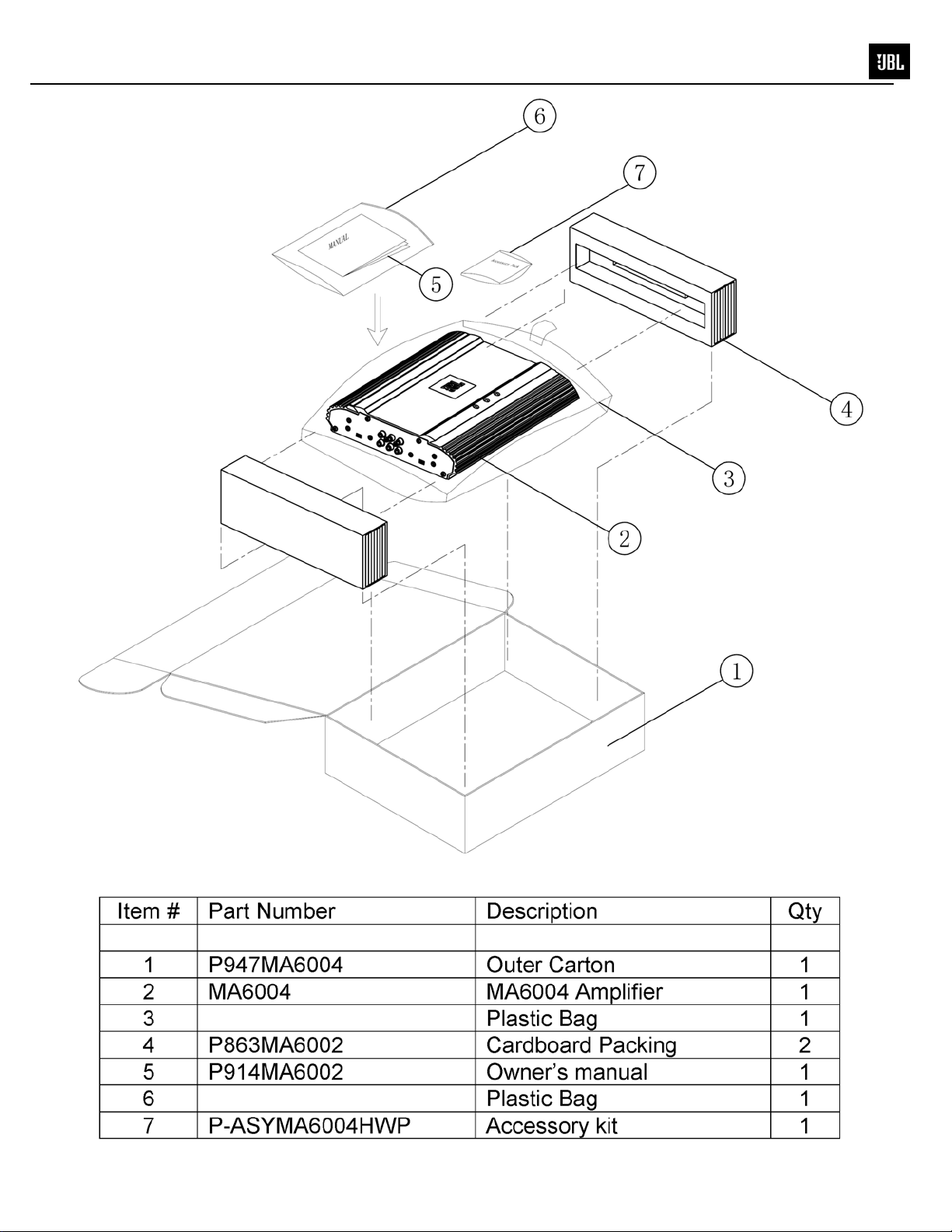
MA6002 PACKING……..………………….….….….……...4
MA6004 PACKING…………………………………..………5
CONNECTIONS……………………………........................6
OPERATION ……..………………………………….….…...9
BASIC TROUBLESHOOTING…………………….………..9
MA6002 EXPLODED VIEW/PARTS LIST……………….10
MA6004 EXPLODED VIEW/PARTS LI ST.......................11
MA6002 BLOCK DIAGRAM………………………….……12
MA6004 BLOCK DIAGRAM………………………….……13
MA6002 ELECTRICAL PARTS LIST ..…… ……...…..…14
MA6004 ELECTRICAL PARTS LIST ..…… ….…………17
MA6002 P.C.B. DRAWINGS……………………..….…….20
MA6004 P.C.B. DRAWINGS………………………..….….22
MA6002/MA6004 IC/TRANSISTOR PINOUTS………….24
MA6002 SCHEMATICS………………………..…….……25
MA6004 SCHEMATICS…………………………..….……28
Basic Specifications
7
MA6002
• 60W RMS x 2 c hannels at 4 ohms and ≤1% THD + N
• Signal - to-noise ratio: 84dBA (reference 1W into 4 ohms)
• 80W RMS x 2 c hannels at 2 ohms, 14.4V suppl y and ≤1% THD + N
• 160W RMS x 1 c hannel at 4 ohms, 14.4V supply and ≤1% THD + N
• Dynamic power: 160W at 2 ohms
• Effectiv e damping factor: 6.395 at 4 ohms
• Frequency response: 10Hz – 27k Hz ( –3dB )
• Maximum input signal: 6V
• Maximum sensitivity: 100mV
• Output r egulation: – 0.03dB at 4 ohms
• Dim ensi ons (L x W x H): 9" x 10-1/4" x 2-3/16" ( 229mm x 261mm x 56mm)
• Fuses: 25A x 1
MA6004
• 60W RMS x 4 c hannels at 4 ohms and ≤1% THD + N
• Signal - to-noise ratio: 80dBA (reference 1W into 4 ohms)
• 80W RMS x 4 c hannels at 2 ohms, 14.4V suppl y and ≤1% THD + N
• 160W RMS x 2 c hannels at 4 ohms, 14.4V suppl y and ≤1% THD + N
• Dynamic power: 145W at 2 ohms
• Effectiv e damping factor: 6.395 at 4 ohms
• Frequency response: 10Hz – 27k Hz ( –3dB )
• Maximum input signal: 6V
• Maximum sensitivity: 100mV
• Output r egulation: – 0.03dB at 4 ohms
• Dim ensi ons (L x W x H): 13- 1/4" x 10-1/4" x 2-3/16" (337mm x 261mm x 56mm )
• Fuses: 25A x 2
V
r
"
)
)
e
2
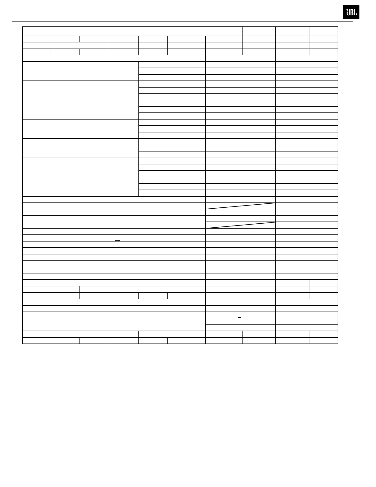
MARINE series MA6002
MA6002 MARINE AMPLIFIER SPECIFICATIONS
TEST VOLTAGE...14.4 +0.1
Nominal Remarks
4ohm loads(stereo mode)for each . ch
@<1.0%THD
(Unit:W)(LPF=22K)
2ohm loads(stereo mode)for each .ch
@<1.0%THD
(Unit:W)(LPF=22K)
BTL/4ohms(mono mode
@<1.0%THD(Unit;W)
LPF=22K
THD and 1MD@Reference
Power 4 ohm loads(Unit:%)
LPF=22K
THD and 1MD@Reference
Power 2 ohm loads(Unit:%)
LPF=22K
THDand 1MD@referenc
Power 4ohms BTL loads
(Unit:%)(LPF=22KHz)
Channel Separation
@full rated power (+80KHZ)
Full rated power Disortion1KHz LPF=22KHz ≤0.1%
Signal/Noise a: 1 watt rate
b: full rated power (dB)
Input Sensitivity Low Level Input( v)
@:full rated power
Frequency response (Unit:-3dB) 10HZ~30KHZ
High-Pass Crossover Frequency limits +
Low-Pass Crossover Frequency limits +
Bass Boost:(Unit:dB) @45HZ (±5Hz ) 0~6dB ±1dB
Idle Current ( @4ohm) 0.5A ±0.15A
MAX current : rated power (All channel 2ohm loads) ≤23A
DC Offset: ≤30mV
Damping Factor (4ohm): >200
Damping Factor (4ohm): 6.395
Dynamic Powe
Output Regulation
Remote Operating Voltages: ON 5V OFF 4V ±1V
Turn on delay time (Seconds)
Circuit Protection a. Temperature
b. Speaker Short Circuit
c. Operating Voltage Range
Dimensions (L x W x H): 9" x 10-1/4" x 2-3/16
Fuses: 25A x 1
20% 32HZ~320HZ
20% 32HZ~320HZ
(229mm x 261mm x 56mm
1KHZ ≥60W x 2
1KHZ ≥80W x 2
1KHZ ≥160W x 1
1KHZ ≤0.3%
1KHZ ≤0.3%
1KHZ ≤0.3%
1KHZ ≥45dB
≥90 1V signal input
100mV-6V ±20%
160W @ 2 ohms
0.03dB @ 4 ohms
2~3
75+
5℃
Yes
10.5~16V
V
r
)
e
3
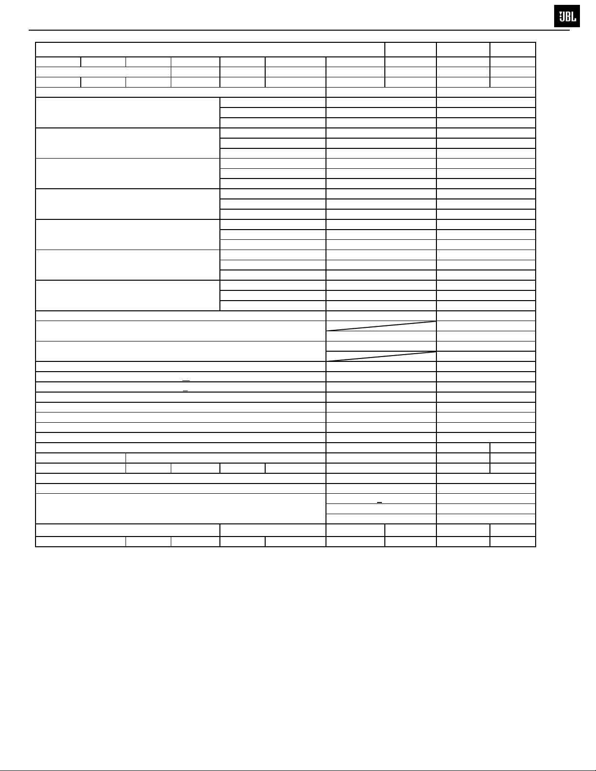
MARINE series MA6004
MA6004 MARINE AMPLIFIER SPECIFICATIONS
TEST VOLTAGE...14.4 +0.1
Nominal Remarks
4ohm loads(stereo mode) for each . ch
@<0.5%THD
(Unit:W)(LPF=22K)
2ohm loads (stereo mode) for each .ch
@<0.5%THD
(Unit:W)(LPF=22K)
BTL/4ohms (mono mode
@<0.5%THD(Unit;W)
LPF=22K
THD and 1MD@Reference
Power4 ohm loads(Unit:%)
LPF=22K
THD and 1MD@Reference
Power 2 ohm loads(Unit:%)
LPF=22K
THDand 1MD@referenc
Power 4ohms BTL loads
(Unit:%)(LPF=22KHz)
Channel Separation
@full rated power (+80KHZ)
Full rated power Disortion1KHz LPF=22KHz ≤0.2%
Signal/Noise a: 1 watt rate
b: full rated power (dB)
Input Sensitivity Low Level Input( v)
@:full rated power
Frequency response (Unit:-3dB) 10HZ~30KHZ
High-Pass Crossover Frequency limits +
Low-Pass Crossover Frequency limits +
Bass Boost:(Unit:dB) @45HZ (±5Hz ) 0~6dB ±1dB
Idle Current ( @4ohm) 0.6A ±0.15A
MAX current : rated power (All channel 2ohm loads) ≤45A
DC Offset: ≤30mV
Damping Factor (4ohm): >200
Effective Damping Factor (4ohm): 6.395
Dynamic Powe
Output Regulation
Remote Operating Voltages: ON 5V OFF 4V ±1V
Turn on delay time (Seconds)
Circuit Protection a. Temperature
b. Speaker Short Circuit
c. Operating Voltage Range
Dimensions (L x W x H): 13-1/4" x 10-1/4" x 2-3/16"
Fuses: 25A x 2
20% 32HZ~320HZ
20% 32HZ~320HZ
(337mm x 261mm x 56mm)
1KHZ ≥50W*4
1KHZ ≥75W*4
1KHZ ≥150W*2
1KHZ ≤0.5%
1KHZ ≤0.5%
1KHZ ≤0.5%
1KHZ ≥45dB
≥90 1V signal input
100mV-6V ±20%
145W @ 2 ohms
0.03dB @ 4 ohms
2~3
75+
5℃
Yes
10.5~16V
4
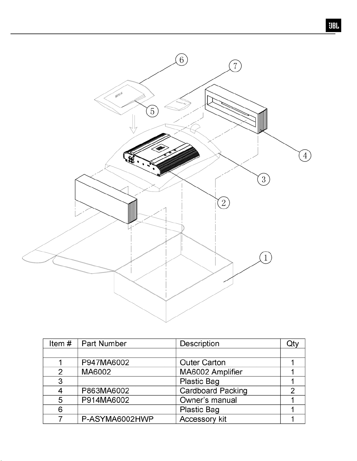
MARINE series MA6002
MA6002 PACKAGE
5
MARINE series MA6004
MA6004 PACKAGE
NC
NO
+
12V
AMP REM
6
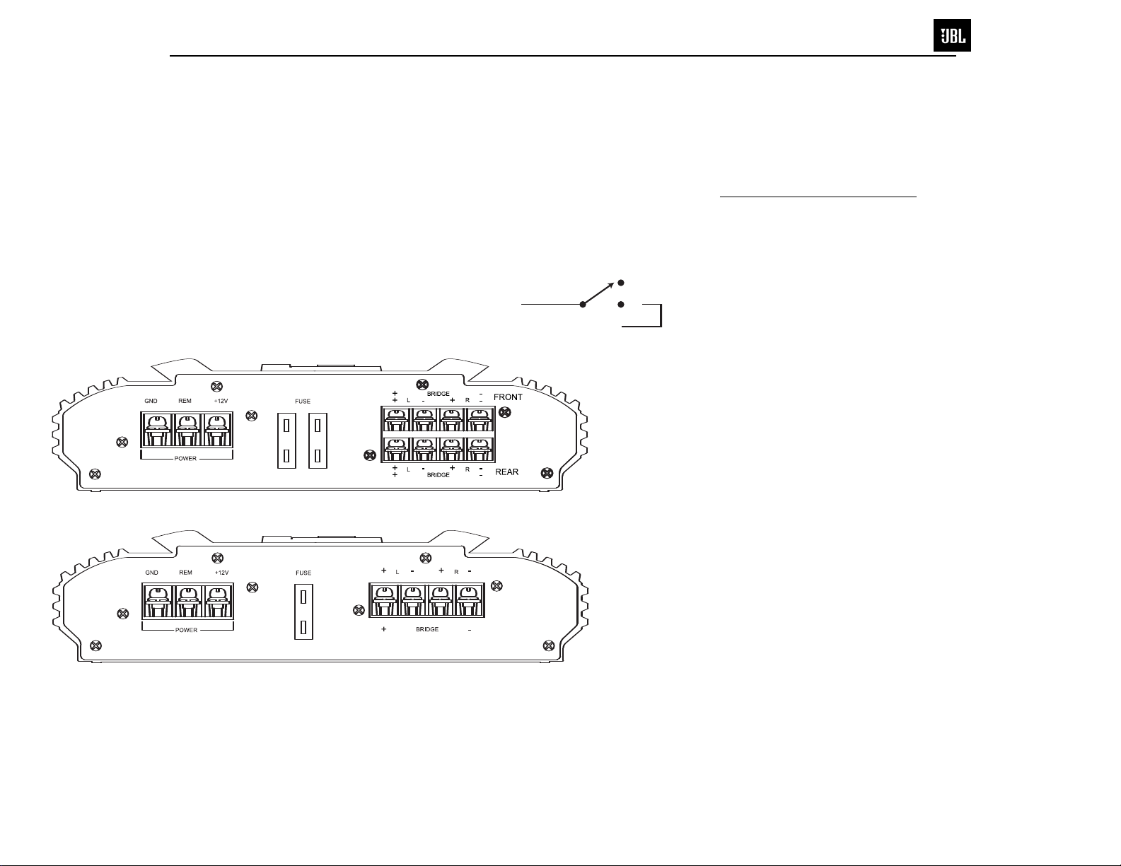
INSTALLATION
MARINE series MA6002/6004
POWER CONNECTIONS
The amplifier requires a reliable
connection to the boat’s electrical
system in order to perform optimally.
See Figures 1 and 2 for terminal connection locations. Please adhere to
the following instructions carefully:
Ground Connection
Connect the amplifier’s Ground (GND)
terminal to the battery’s negative terminal,
using a ring terminal. Refer to the wire gauge
chart to determine minimum wire gauge size.
Figure 1. Terminal connection end plate for MA6004.
Power Connection
Connect a wire (see chart at right for
appropriate gauge) directly to the positive
battery terminal, and install an appropriate
fuse holder within 18" of the battery terminal.
Do not install the fuse at this time. Route
the wire to the amplifier’s location, and
connect it to the amplifier’s Positive (+12V)
terminal. Be sure to use appropriate
grommets whenever routing wires through
a bulkhead or other obstruction.
adequately protect the positive wire from
potential damage may result in a fire. When
you are done routing and connecting this
wire, you may install the fuse at the battery.
Failure to
Remote Connection
Connect the amplifier’s Remote (REM)
terminal to the source unit’s Remote TurnOn lead using a minimum of 18-gauge wire.
NOTE: If your source unit does not have
a remote turn-on connection, connect
the amplifier’s (REM) terminal to a wire
that provides +12V when the boat’s accessories are on or when the key is switched
on. If no such circuit exists, install a
switch. See Figure 3.
Figure 3. Install a switch for the Remote
Turn-On lead.
Speaker Connections
Refer to the application guides on the
pages that follow. Speaker connections
should be made using a minimum of
16-gauge wire.
Wire Gauge Chart
Amplifier Maximum Minimum
Model Current Draw Wire Gauge
MA6002 22A #8 AWG
MA6004 40A #8 AWG
These recommendations assume 10' – 12'
wire runs. If your amplifier will be mounted
farther than 12' from the boat’s battery, use
a larger gauge.
Figure 2. Terminal connection end plate for MA6002.
3
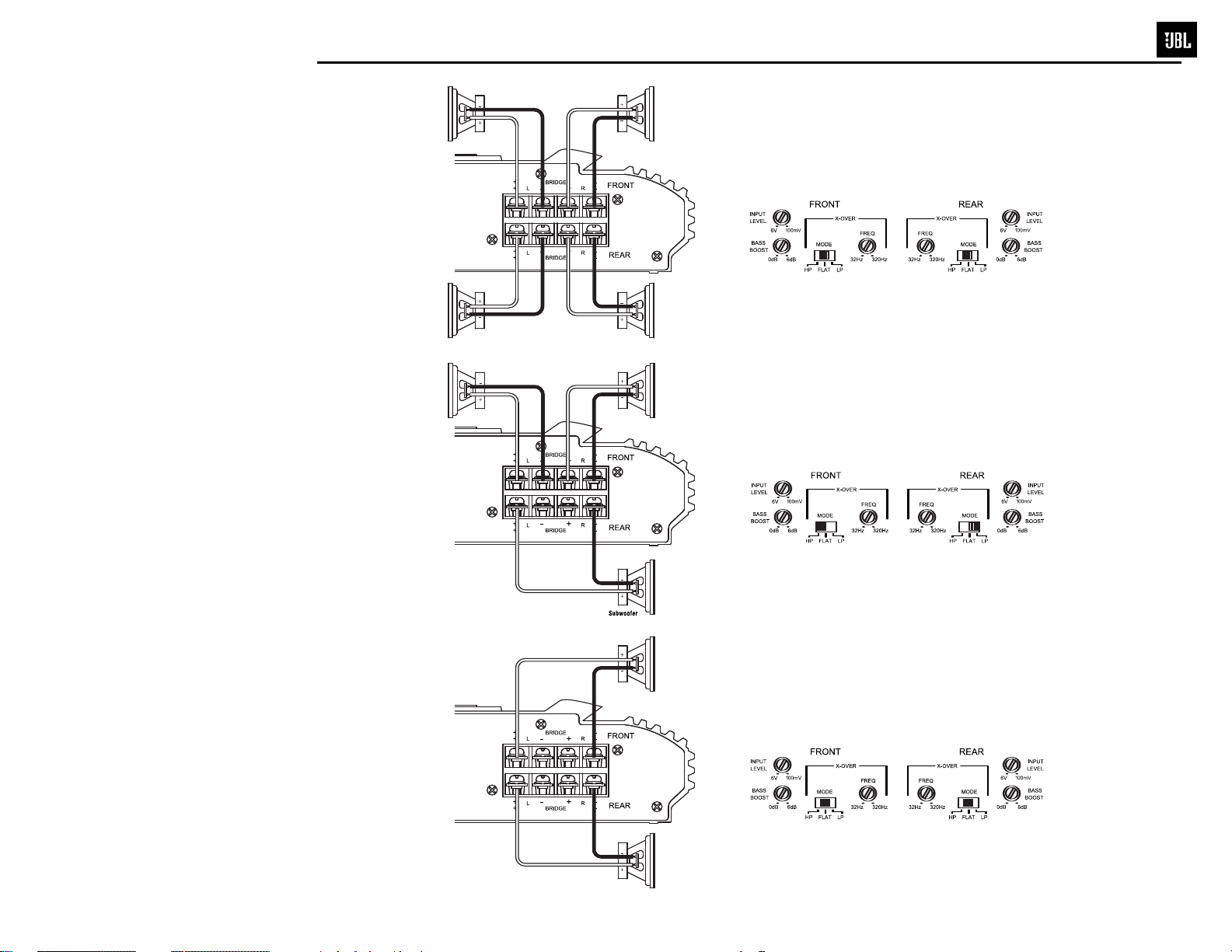
APPLICATIONS – MA6004
Front RightFront Left
R
ear RightRear Left
F
ront RightFront Left
Rear RightRear Left
F
ront RightFront Left
F
ront RightFront Left
7
The MA6004 can be set up for stereo
4-channel, 3-channel or bridged
2-channel operation, as shown in
Figures 4 through 6.
NOTE: For simplicity, Figures 4 through
6 do not show power, remote and input
connections.
NOTE: Minimum speaker impedance
for stereo operation is 2 ohms.
Minimum speaker impedance for
bridged operation is 4 ohms.
Figure 4. MA6004 amplifier in 4-channel (stereo)
operation to drive front and rear full-range speakers.
Figure 5. MA6004 is set up for 3-channel operation
to drive a set of full-range speakers and a subwoofer.
Figure 6. MA6004 used in bridged 2-channel mode to
drive a set of components or subwoofers. Set crossovers
according to application.
4
8
MARINE series MA6002
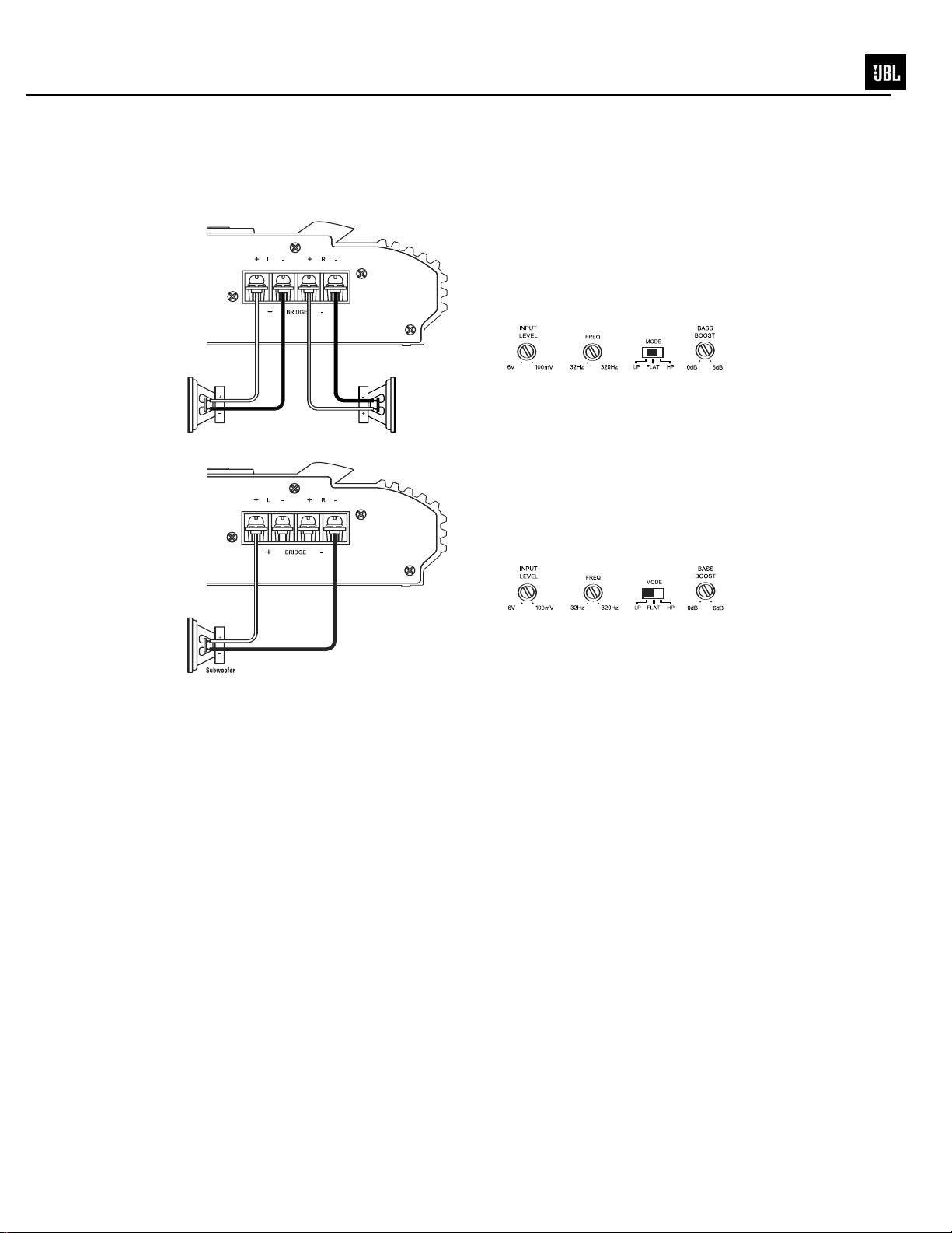
APPLICATIONS – MA6002
Figure 7. MA6002 used in 2-channel (stereo)
operation to drive a set of full-range speakers.
RightLeft
Figure 8. MA6002 used in bridge mode to drive a
subwoofer.

9
MARINE series MA6002/6004
CONTROLS AND SETUP
SETTING THE
CROSSOVER(S)
Determine your system plans and set
the crossover mode switch accordingly.
If your system design does not include
a subwoofer with the MA6004, set the
crossover mode to FLAT; if you are using
speakers that are 5 inches in diameter or
larger, skip to “Setting Input Sensitivity.”
Initially set the crossover frequency
control midway. While listening to music,
adjust the crossover for the least
perceived distortion from the speakers,
allowing them to reproduce as much
bass as possible.
For systems using a separate subwoofer,
set the crossover mode to HP (high pass)
for your full-range speakers. Adjust the
crossover frequency to limit bass and
provide increased system volume with
less distortion.
For subwoofers, choose the highest
frequency that removes vocal information
from the sound of the subwoofer.
If using the MA6004 or MA6002 to drive a
subwoofer(s), set the crossover mode to
LP (low pass).
SETTING INPUT
SENSITIVITY
1. Initially turn the INPUT LEVEL control(s)
to minimum (counter clockwise).
2. Reconnect the (–) negative lead to the
boat’s battery. Apply power to the audio
system and play a dynamic music track.
3. On the source unit, increase the volume
control to 3/4 volume. Slowly increase
the INPUT LEVEL control(s) toward
“three o’clock” until you hear slight
distortion in the music. Then reduce
the INPUT LEVEL slightly until distortion
is no longer heard.
NOTE: After the source unit is on,
blue LEDs (on the top panel) will light,
indicating the amplifier is on. If not,
check the wiring, especially the remote
connection from the source unit. Also
refer to the “Troubleshooting” guide.
TROUBLESHOOTING
SYMPTOM LIKELY CAUSE SOLUTION
No audio No voltage at BATT+ Check voltages at
(POWER LEDs or REM terminals, amplifier terminals
are off) or bad or no ground with VOM
connection
No audio Amplifier is Make sure amplifier
(POWER overheated cooling is not blocked
LEDs are on) at mounting location;
Voltage more than 16V Check boat’s battery
or less than 8.5V on charging system
BATT+ connection
No audio Voltage less than 9V on Check boat’s
(POWER BATT+ connection charging system
LEDs flash)
DC voltage on Amplifier may need
amplifier output service; see enclosed
Distorted audio Input sensitivity is Check INPUT
not set properly, or LEVEL setting; or
amplifier or source check speaker wires
unit is defective for shorts or grounds
Distorted audio Short circuit in Remove speaker leads
and POWER speaker or wire one at a time to locate
LEDs flash shorted speaker or
Music lacks Speakers are not Check speaker
“punch” connected properly connections for
verify speaker-system
impedance is within
specified limits
warranty card for
service information
wire, then repair
proper polarity
6
 Loading...