

Page 1
GT5-A3001
1 CHANNEL POWER AMPLIFIER
SERVICE MANUAL
Released 2007
Discontinued XXXX
JBL Consumer Products
250 Crossways Park Dr.
Woodbury, New York 11797 Rev0 3/2008
Page 2

1
GT5-A3001
- CONTENTS -
SPECIFICATIONS ………………………………………..1
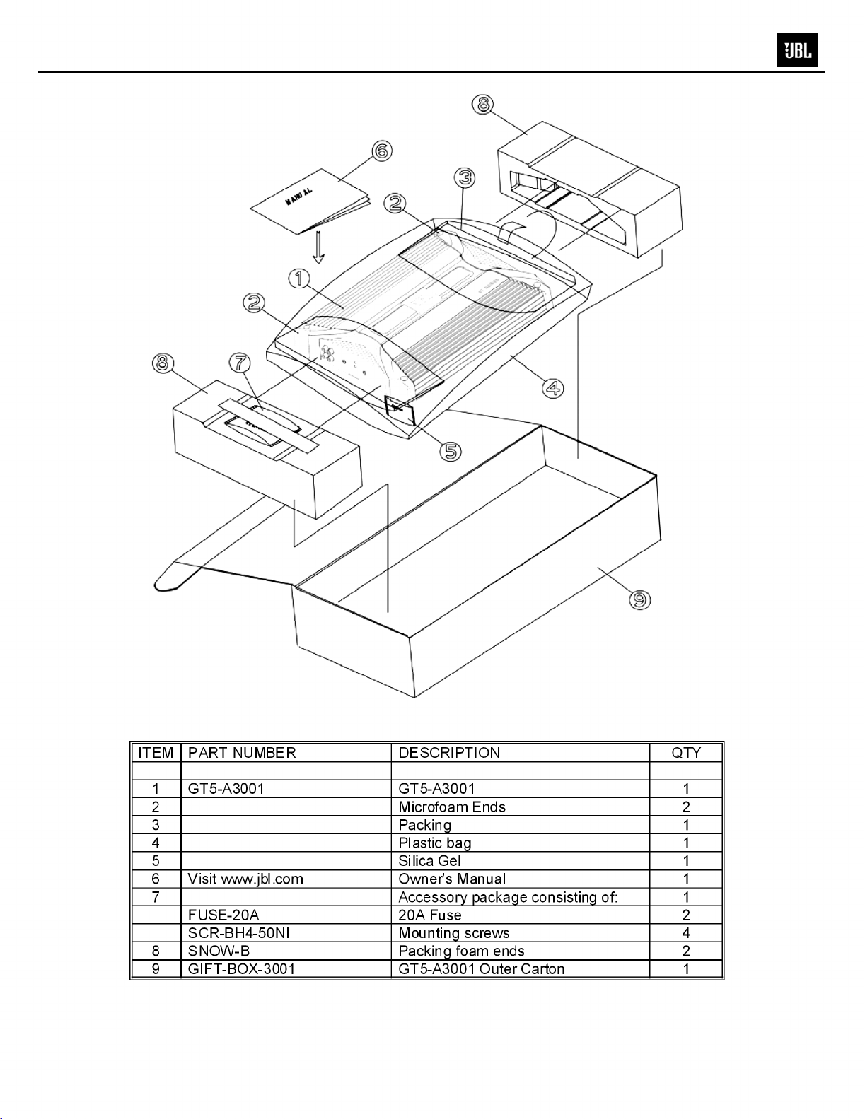
PACKING……………………………………………..…....2
CONTROL/INSTALLATION DRAWINGS………………3
CONTROL/INSTALLATION INSTRUCTIONS………....4
BASIC TROUBLESHOOTING……………………………5
EXPLODED VIEW/PARTS LIST…….….….…………....6
AMPLIFIER BLOCK DIAGRAM…………………….……7
ELECTRICAL PARTS LIST ..……….……….…….…….8
P.C.B. DRAWINGS….………………………...…….……11
IC/TRANSISTOR PINOUTS..…………………….….…..13
SCHEMATICS……………..……………….………..…...14
GT5-A3001 Specifications
Output Power: 175W RMS x1 channels @ 4 ohms; ≤1% THD + N
(14.4V supply) 225W RMS x 1 channels @ 2 ohms; ≤1% THD + N
300W RMS x 1 channel @ 1 ohm; ≤1% THD + N
Signal-to-noise ratio: 95dBA (reference 1W into 4 ohms)
120dBA (reference rated power into 4 ohms)
Total Peak power: 600W
Frequency response: 10Hz – 300Hz (–3dB)
THD+N 1KHz LPF=22KHz ≤0.05% (rated power @ 4 ohms)
Input Impedance 10kΩ
Maximum input signal: 6.0V
Maximum sensitivity: 200mV
Hi-Pass, Low Pass X-over Limits 32Hz – 320Hz ±20% 12dB/oct
DC Offset <30mV
Output regulation: 46dB
Idle Current @ 4 ohms 400mA
Max Current Draw ≤20A
Remote Operating Voltage 5V
Turn-on delay time 3 sec
Circuit Protection Temperature (85±5C), Short circuit, Operating voltage range (8-16V)
Dimensions: 2 1/8 x 9 1/4 x 12" (54 x 235 x 305mm)
Fuse: 2 x 20A
JBL continually strives to update and improve existing products, as well as create new ones. The specifications and details in
this and related JBL publications are therefore subject to change without notice.
Page 3
2
GT5-A3001
Page 4
ABCD
A
2x
4x
1x
9-1/4"
235mm
2-1/8"
54mm
12"
305mm
3
GT5-A3001
Page 5
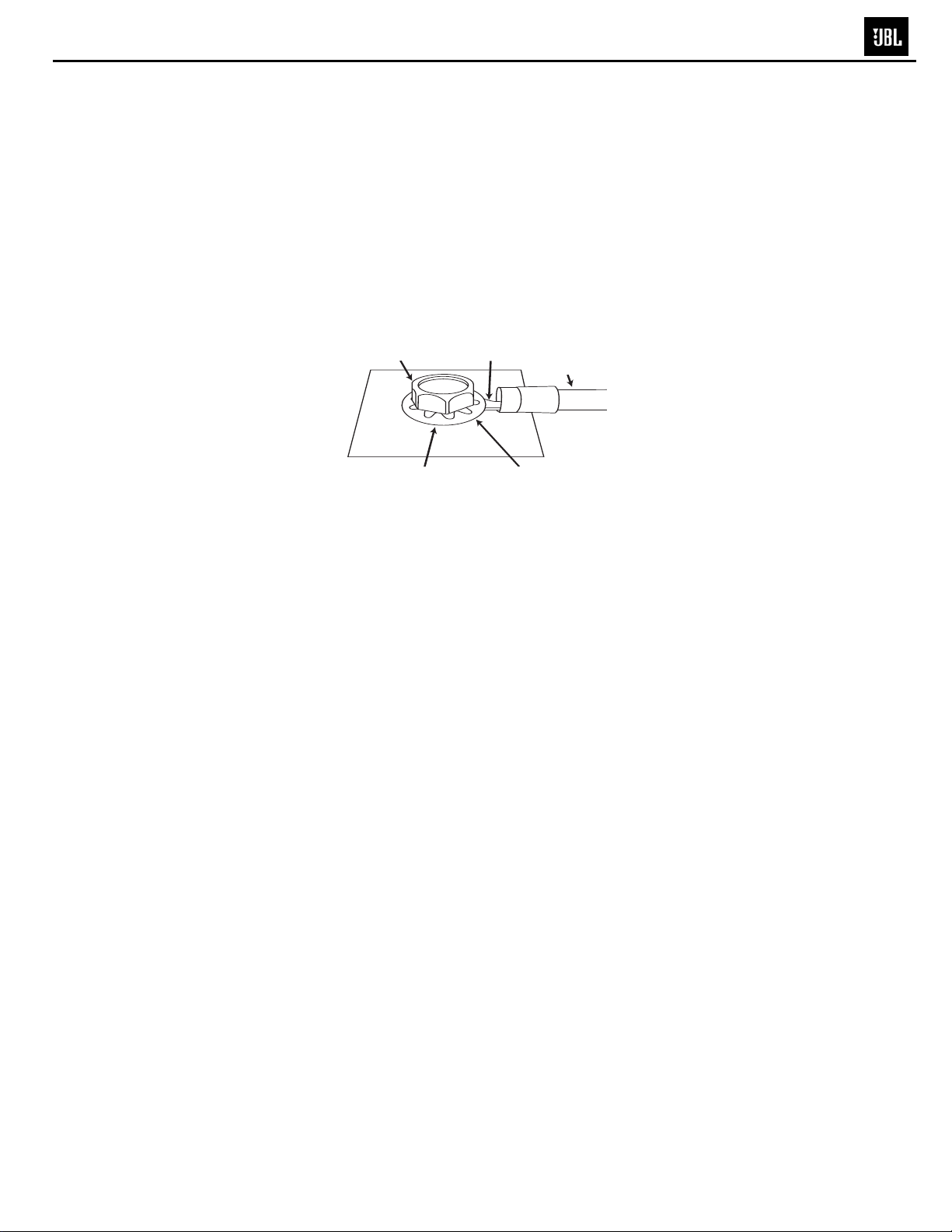
Factory Bolt Ring Connector
G
round Wire
Note: Remove any paint
below ring connector.
Star Washer
4
GT5-A3001
GT5-A3001 CAR AUDIO SUBWOOFER AMPLIFIER OWNER’S MANUAL
Installation Warnings and Tips
• Disconnect the negative (–) lead from your vehicle’s
battery.
• At the installation sites, locate and make a note of
all fuel lines, hydraulic brake lines, vacuum lines
and electrical wiring. Use extreme caution when
cutting or drilling in and around these areas.
• Choose a safe mounting location away from moisture.
• Make sure there is sufficient air circulation at the
mounting location for the amplifier to cool itself.
• Mount the amplifier, using the supplied hardware.
Specifications
• 175W RMS x 1 channel @ 4 ohms and ≤1% THD + N*
• 225W RMS x 1 channel @ 2 ohms, 14.4V supply and
≤1% THD + N*
• 300W RMS x 1 channel @ 1 ohm, 14.4V supply and
≤1% THD + N*
• THD + N: 0.05% (rated power @ 4 ohms)*
• Signal-to-noise ratio: 95dBA
(reference 1W into 4 ohms)*
• Signal-to-noise ratio: 120dBA
(reference rated power into 4 ohms)
• Frequency response: 10Hz – 300Hz (–3dB)*
• Total peak power: 600 watts
* CEA-2006A-compliant
0
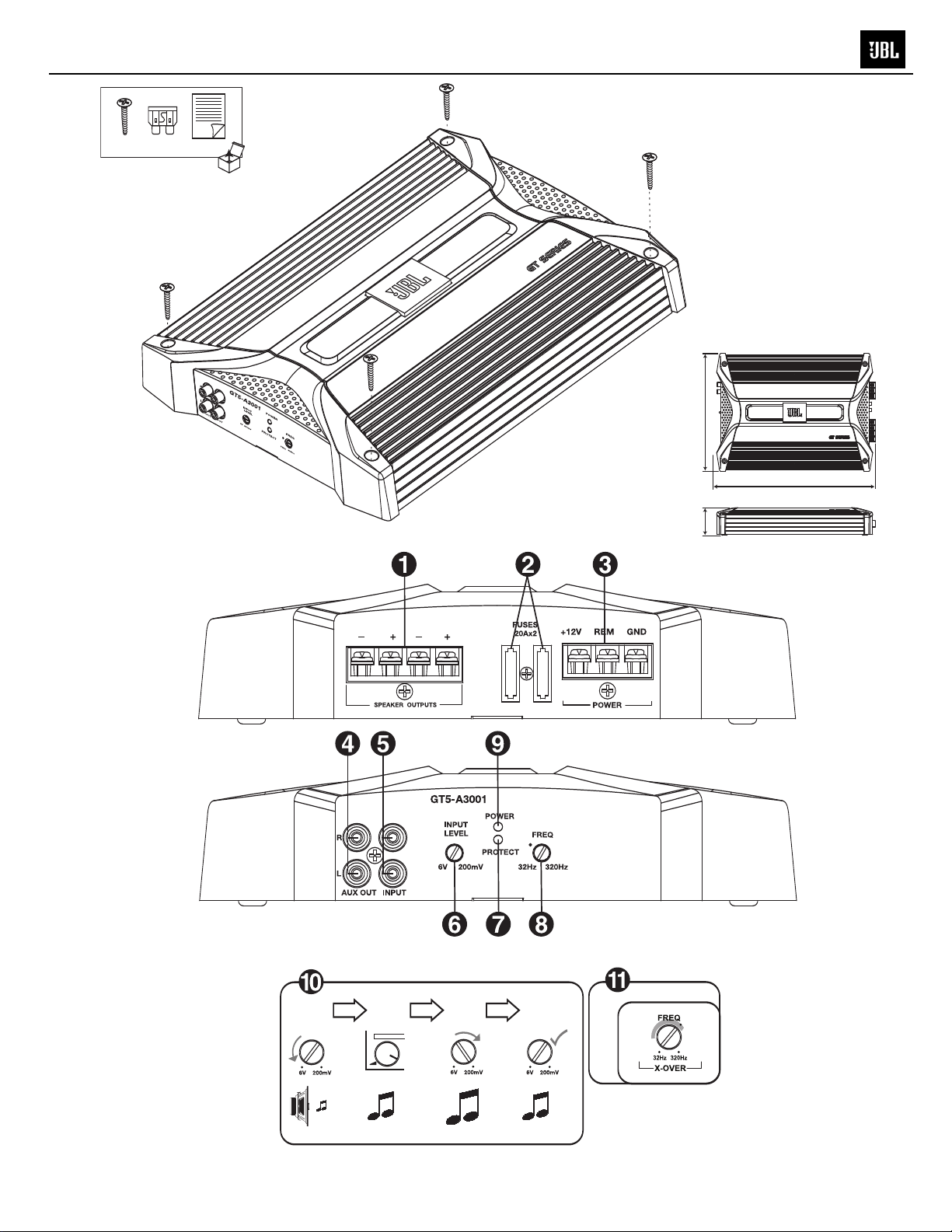
Speaker Output Connectors
• Connect the subwoofer to these terminals,
observing proper polarity. Either + or –
terminal may be used. Minimum total
impedance is 1 ohm.
1
Fuses
• Replace only with the same type and rating.
2
Power Input Connectors
• +12V: Connect to the positive terminal of the
vehicle’s battery. 8 AWG wire is recommended.
Install an appropriate fuse holder and fuse (40A
minimum) within 18 inches of the battery. Make
sure the wire is not damaged or pinched during
installation. Install protective grommets when
routing wires through the firewall or other sheet
metal.
• GND: Connect to the vehicle’s chassis. Refer to
the picture below.
• REM: Connect to the “Remote Out” lead from
the source unit or to a source of switched
12V+ (ACC).
3
Aux Output Connectors (RCA)
• Nonfiltered pass-through output. Connect to
the input of an additional amplifier.
4
Input Connectors (RCA)
• Connect to the RCA outputs from the source unit
or signal processor.
5
Input-Level Control
• Used to match the input level of the amplifier
to the output level of the source unit.
• See 9for the adjustment procedure.
6
Protect LED
• Illuminated under any of the following fault
conditions: battery over/under voltage, short
circuit in speaker wires, amplifier is too hot,
amplifier’s output circuit has failed (DC voltage
is present in the amplifier’s output).
7
Low-Pass Filter Frequency Control
• 12dB/octave low-pass filter,
variable from 32Hz to 320Hz.
• See Afor the adjustment procedure.
8
Power On LED
• Illuminated when the amplifier is on.
9
Setting Input Level
A Turn Input Level control counterclockwise to
6V (minimim).
B With a dynamic music track playing, turn the
head unit’s volume control to the 3/4 position.
C Turn Input Level control clockwise until the
bass output is proportionate to the output of
the high-frequency speakers, according to
your preference.
D Input level is now adjusted correctly.
A
Setting the Crossover
A Crossover setting for subwoofers.
Note: Acceptable frequency ranges are indicated
in gray.
Page 6

5
GT5-A3001
Amplifier Troubleshooting Guide
1. Status LED on Amplifier not Lit - Head Unit (Source) Turned ON
Verify:
A. Remote turn-on wire from source to amplifier has proper voltage
B. Power (B+) connections at amplifier, terminal blocks, and battery are secure
C. Ground (GND) connections at amplifier and vehicle chassis are secure
D. Battery B+ fuse (if used) is OK
E. Amplifier fuse is OK
F. B+ at battery and B+ at amplifier has proper voltage
2. Status LED’s Lit, No Output from Speakers in Normal Operating Condition
Verify:
A. RCA cables from amplifier to source are securely connected
B. Volume adjustment on amplifier is correctly adjusted
C. Source is ON and playing
3. Engine Noise From Speaker(s)
Turn source OFF, Disconnect RCA cables at amplifier. If noise stops, check equipment & cables leading
to ampli fier.
Verify:
A. RCA cables ar e o f good quality wit h no bre ak a ge to i nternal shiel ds
B. RCA cables from source to amplifier are not run alongside any power cables
4. Amplifier Output Distorted Music
Verify:
A. Source output music to amplifier is not distorted
B. Source output sensitivity is correctly adjusted
5. Amplifier Shuts Down, Green LED’s are Lit - Amplifier is in Thermal Protection Mode
Verify:
A. Amplifier is mounted with adequate air circulation around heatsinks or vents
B. Amplifier is not mounted under carpet or sealed enclosure
C. Speakers meet correct impedance for application (mono or stereo hookup)
6. Amplifier Does Not Turn ON, and Red LED is Lit Amplifier (and not Connected to a Shorted Speaker)
Verify:
A. Speaker crossover (if used) is not defective
Page 7

6
GT5-A3001
Page 8

7
GT5-A3001
Page 9

8
GT5-A3001
GT5-A3001 Electrical Parts List
Part Number Qty Reference Designator
Semiconductors
TR-KTA1266GR TRANS SMALL SIGNAL PNP "TO-92"KTA1266GR 4 Q03,04,08,09
TR-KTA1268GR TRANS SMALL SIGNAL PNP "TO-92"KTA1268GR 5 Q06,102,103,107,108
TR-KTC3198BL TRANS SMALL SIGNAL NPN,TO-92KTC3198BL 1 Q05
TR-KTC3198GR TRANS SMALL SIGNAL NPN,TO-92KTC3198GR 4 Q02,07,131,132
TR-KTC3200GR TRANS SMALL SIGNAL NPN,TO-92KTC3200GR 4 Q104,105,106,130
TR-KTA1023Y TRANS SMALL SIGNAL PNP "TO-92"KTA1023Y 4 Q01,113,122,125
TR-KTC1027Y TRANS SMALL SIGNAL NPN,TO-92KTC1027Y 4 Q109,112,119,123
DIODE-1N4148 DIODE SWITCHING SIGNAL1N4148 10 D03,04,05,08,09,101,102,103,104,105
DIODE-1N4004 DIODE RECTIFIER1N4004 1 D01
DIODE-FR154 DIODE FAST RECOVERYFR154/1504 4 D11,12,13,14
DIODE-1N4744 DIODE ZENER, 15V/1W1N4744 2 D15,16
IC-TL494CN IC PWM IC,DIP-16TL494CN 1 U01
IC-NJM2068D IC DUAL OP AMP,DIP-08 NJM2068D 4 U101,102,103,104
FET-K30AGR FET N-CH JFET,TO-92KTK30AGR 2 Q17,101
FET-50N60P FET N-CH POWER MOS FET,TO-220KEC50N60P 6 Q11 12 13 14 15 16
TR-TIP35CA TRANS AUDIO POWER NPN,TO-3P TIP35CA 3 Q111,116,124
TR-TIP36CA TRANS AUDIO POWER PNP,TO-3P TIP36CA 3 Q117,120,126
TR-KTC3200GR1 TRANS SMALL SIGNAL NPN,TO-92KTC3200GR 1 Q110
DIODE-1N5404 DIODE RECTIFIER1N5404 1 D02
DIODE-YG225D2 DIODE FAST RECOVERY, TO-220YG225D2 2 D06 07
LED1 LED ACYLE 3.0 AWG#24,RED/BLACK200m/m 1 LOGO BACKLIGHT
LED0 LED 3PHI,GREEN & REDL-H322005GB 1 LED01
Description
Capacitors - see legend last page
CAP0501R0-E CAPACITOR ELECTROLYTIC"MHA" ,5*11m/m 1/50V 1 C129
CAP0502R2-E CAPACITOR ELECTROLYTIC"MHA" ,5*11m/m 2.2/50V 2 C120,153
CAP0504R7-E CAPACITOR ELECTROLYTIC"MHA" ,5*11m/m 4.7/50V 2 C112,212
CAP016100-E CAPACITOR ELECTROLYTIC"MHA" ,5*11m/m 10/16V 3 C02,100,200
CAP025100-E CAPACITOR ELECTROLYTIC"MHA" ,5*11m/m 10/25V 1 C09
CAP050100-E CAPACITOR ELECTROLYTIC"MHA" ,5*11m/m 10/50V 1 C39
CAP016220-E CAPACITOR ELECTROLYTIC"MHA" ,5*11m/m 22/16V 4 C101,102,201,202
CAP016470-E CAPACITOR ELECTROLYTIC"MHA" ,5*11m/m 47/16V 3 C04, 06,107
CAP025470-E CAPACITOR ELECTROLYTIC"MHA" ,5*11m/m 47/25V 2 C10,125
CAP016101-E CAPACITOR ELECTROLYTIC"MHA" ,5*11m/m 100/16V 3 C05, 07 12
CAP025221-E CAPACITOR ELECTROLYTIC"MHA/SD"220/25V 1 C42
CAP025331-E CAPACITOR ELECTROLYTIC"MHA/SD"330/25V 1 C43
CAP035101-E CAPACITOR ELECTROLYTIC"MHA/SD"100/35V 2 C40 41
CAP016221-E CAPACITOR ELECTROLYTIC"MHA" ,6*12m/m220/16V 1 C142
CAP100102-M CAPACITOR MYLAR,100V 5%102(M) 2 C11 31
CAP100683-M CAPACITOR MYLAR,100V 5%683(M) 1 C110
CAP100104-M CAPACITOR MYLAR,100V 5%,BOX or TL104(M) 6 C25 26 36 37 109 261
CAP063105-M CAPACITOR MYLAR,63V 5%,BOX or TL105(M) 1 C01
CAP050100-C CAPACITOR DISK TYPE, CERAMIC, 50V"NPO" 10P 2 C105.205
CAP050220-C CAPACITOR DISK TYPE, CERAMIC, 50V"NPO" 22P 7 C103,104,111,203,204,211,38
CAP050470-C CAPACITOR DISK TYPE, CERAMIC, 50V"NPO" 47P 2 C106,130
CAP050680-C CAPACITOR DISK TYPE, CERAMIC, 50V"NPO" 68P 1 C123
CAP050331-C CAPACITOR DISK TYPE, CERAMIC, 50V"NPO" 330P 1 C128
CAP050271-C CAPACITOR DISK TYPE, CERAMIC, 50V 270P 2 C131,132
CAP050102-C CAPACITOR DISK TYPE, CERAMIC, 50V 102P 2 C108,124
CAP050473-C CAPACITOR DISK TYPE, CERAMIC, 50V 473P 1 C24
CAP050104-C CAPACITOR DISK TYPE, CERAMIC, 50V 104P 4 C03 08 23 140
CAP050471-E CAPACITOR ELECTROLYTIC"MHA" 470/50V 2 C32 33
CAP025222-E CAPACITOR ELECTROLYTIC"WL" 2200/25V 2 C21 22
CAP050222-E CAPACITOR ELECTROLYTIC"SHL" 2200/50V 2 C34 35
CAP-050101E CAPACITOR ELECTROLYTIC"MHA" 100/50V 2 C122 127
Resistors
RES68001/8-F RESISTOR METAL FILM 1/8WF 680 1 R109
RES56001/8-F RESISTOR METAL FILM 1/8WF 560 1 R112
Page 10

9
GT5-A3001
Part Number Qty Reference Designator
RES12011/8-F RESISTOR METAL FILM 1/8WF 1.2K 1 R124
RES47011/8-F RESISTOR METAL FILM 1/8WF 4.7K 3 R106,107,09
RES56011/8-F RESISTOR METAL FILM 1/8WF 5.6K 3 R113,114,121
RES94011/8-F RESISTOR METAL FILM 1/8WF 9.4K 2 R105,205
RES10021/8-F RESISTOR METAL FILM 1/8WF 10K 5 R111,115,116,215,216
RES12021/8-F RESISTOR METAL FILM 1/8WF 12K 1 R273
RES22021/8-F RESISTOR METAL FILM 1/8WF 22K 2 R100,200
RES47021/8-F RESISTOR METAL FILM 1/8WF 47K 8 R101,102,103,104,201,202,203,204
RES10521/8-F RESISTOR METAL FILM 1/8WF 10.5K 1 R08
RES1001/8-J RESISTOR CARBON FILM 1/8W 10 7 R15,142,143,151,152,156,157
RES4701/8-J RESISTOR CARBON FILM 1/8W 47 7 R33 34 35 38 39 40 128
RES1011/8-J RESISTOR CARBON FILM 1/8W 100 1 R108
RES1211/8-J RESISTOR CARBON FILM 1/8W 120 1 R132
RES5611/8-J RESISTOR CARBON FILM 1/8W 560 3 R140,150,158
RES6811/8-J RESISTOR CARBON FILM 1/8W 680 1 R123
RES7511/8-J RESISTOR CARBON FILM 1/8W 750 1 R16
RES8211/8-J RESISTOR CARBON FILM 1/8W 820 1 R131
RES1021/8-J RESISTOR CARBON FILM 1/8W 1K 9 R117,118,122,217,218,07 17 32 37
RES1521/8-J RESISTOR CARBON FILM 1/8W 1.5K 4 R25,125,129,160
RES4721/8-J RESISTOR CARBON FILM 1/8W 4.7K 4 R01,02,11,12
RES8221/8-J RESISTOR CARBON FILM 1/8W 8.2K 2 R05 R137
RES1031/8-J RESISTOR CARBON FILM 1/8W 10K 5 R13,14 45 46,272
RES1231/8-J RESISTOR CARBON FILM 1/8W 12K 1 R127
RES1531/8-J RESISTOR CARBON FILM 1/8W 15K 4 R20,21,110,161
RES2231/8-J RESISTOR CARBON FILM 1/8W 22K 4 R22,18 24 126
RES3331/8-J RESISTOR CARBON FILM 1/8W 33K 1 R19
RES4331/8-J RESISTOR CARBON FILM 1/8W 43K 1 R10
RES4731/8-J RESISTOR CARBON FILM 1/8W 47K 1 R23
RES5631/8-J RESISTOR CARBON FILM 1/8W 56K 2 R04,165
RES1041/8-J RESISTOR CARBON FILM 1/8W 100K 2 R119,219
RES2241/8-J RESISTOR CARBON FILM 1/8W 220K 1 R44
RES4341/8-J RESISTOR CARBON FILM 1/8W 430K 1 R06
RES2211/4-J RESISTOR CARBON FILM 1/4WJ 220/0.25W 2 R31 36
RES4R71/2-J RESISTOR METAL FILM 1/2WJ 4.7/0.5W 1 R261
RES1001/2-J RESISTOR METAL FILM 1/2WJ 10/0.5W 3 R03,138,145
RES1011/2-J RESISTOR METAL FILM 1/2WJ 100/0.5W 2 R133,134
RES2421/2-J RESISTOR METAL FILM 1/2WJ 2.4K/0.5W 1 R47
RES1012-J RESISTOR MOR, 2WJ 100/2W 1 R41
RES1512-J RESISTOR MOR, 2WJ 150/2W 2 R42 43
RES6812-J RESISTOR MOR, 2WJ 680/2W 1 R264
RES0R15-J RESISTOR MOR, 5WJ 0.1/5W 6 R147,148,153,154,159,188
3B20Kx2 LEVEL POT B20Kx2V12L5 15S-3B20Kx2 1 VR101
15C50Kx2 FREQ POT 15C50Kx2V12L5 15S-15C50Kx2 1 VR102
Description
Miscellaneous
RET94011/8-F THERMISTOR DISK TYPE,NTC 50KFTD5-350 1 TH01
CORE-GT3001 TRANSFORMER
CORECL-310 INDUCTOR BAR CORECL-310 1 L01
CORECL-510 INDUCTOR BAR CORECL-510 2 L02 03
TER-3P 3P TERMINAL PLATED,3P, POWER JSZ3-02 1 P01
TER-4P 4P TERMINAL PLATED,4P, SPEAKER JSZ4-03 1 P02
AV4-8.4-13A RCA JACK PLATED(TOP:WHITE, BTM:RED)AV4-8.4-13A 1 RCA01
20PWF-9404 FUSE HOLDER 2PWF-9404 1 FH01
FUSE-20A
PLAL0640-02P 2P NEILSBED 2PLAL0640-02P 1 CONN01
JUMPER-37MM cuprum NI-PLATE37m/m 1 BJ01
JUMPER-55MM cuprum NI-PLATE55m/m 1 BJ02
W-60MM GROUND 1007,AWG#24,4.5PHI RING LUG60m/m 1 W1
FIBER8-200 SLIP FIBER, 200.0x8.0x0.5t 0.5 for FET
FIBER6-200 SLIP FIBER, 200.0x6.0x0.5t 0.5 for POWER TR
HEA-GT3001 HEATSINK AL/Die-casting L=290.0mm 1 BLACK SPRAY
END CAP END CAP ABS(XR401) 2 SILVER(8400C) SPRAY END CAP
PAN-RGT3001 FRONT PANEL EGI,1.2t 1 BLACK SPRAY / SILVER SILK 1˚
PAN-FGT3001 REAR PANEL EGI,1.2t 1 BLACK SPRAY / SILVER SILK 1˚
FUSE FUSE 20A 1 FH01
37PHI,ISU37PHI 6t(0.7x15):19t(0.7x5)+9t(0.7x1) 1 T01
Page 11

10
GT5-A3001
Part Number Qty Reference Designator
BOTC-GT604 BOTTOM COVER SECC,1.0t 1 BLACK SPRAY
LOGO-B-PC LOGO BADGE PC(ORANGE CLEAR) 1 HOT STAMPING
JIG-30-15 TRANS CLAMP SPCC 30x15x3(mm) 2 WITH SLIP 48.152.0280130011
JIG-61-15 TRANS CLAMP SPCC 61x15x3(mm) 1 WITH SLIP 48.152.0600140011
JIG-74-15 TRANS CLAMP SPCC 74x15x3(mm) 2 WITH SLIP 48.152.0730140011
PAD-80-23 SILICON PAD (SP1000)80.0x23.0x0.2t 2
PAD-100-23 SILICON PAD (SP1000)100.0X23.0x0.2t 1
RUB10-10-2 RUBBER RUBBER,10.0x10.0x2.0t 1
SCR-BH3-8BK SCREW STT2 BH 3x8 BK 3 RCA(2),TERMINAL(3)
SCR-PH3-8BK SCREW STT2 PH 3x8 BK 1 FUSE(1)
SCR-MB3-6NI SCREW SMB 3x6 NI-P 6 PCB+HEATSINK(6)
SCR-FH3-8BK SCREW STT3 FH 3x8 BK 8 PANEL+HEATSINK(8) SIDE
SCR-MB3-6BK SCREW SMB 3x6 BK 8
SCR-BH3-5NI SCREW STT2 BH 3X5 NI WASHER 2 BADGE
SCR-MB4-14NI SCREW SMB 4X14NI LOCK HEAD 8 TR BRACKET
SCR-BH3-6NI SCREW STT2 BH 3X6 NI-P 1
Description
PANEL+HEATSINK(2) TOP HEAT SINK +BOTTOM COVER(6)
General Capacitance Codebreaker Chart
pico-farad
(pF)
1000 1 or 1n 0.001 102
1500 1.5 or 1n5 0.0015 152
2200 2.2 or 2n2 0.0022 222
3300 3.3 or 3n3 0.0033 332
4700 4.7 or 4n7 0.0047 472
6800 6.8 or 6n8 0.0068 682
10000 10 or 10n 0.01 103
15000 15 or 15n 0.015 153
22000 22 or 22n 0.022 223
33000 33 or 33n 0.033 333
47000 47 or 47n 0.047 473
68000 68 or 68n 0.068 683
100000 100 or 100n 0.1 104
150000 150 or 150n 0.15 154
220000 220 or 220n 0.22 224
330000 330 or 330n 0.33 334
470000 470 or 470n 0.47 474
nano-farad
(nF)
micro-farad
(mF,uF or mfd)
capacitance
code
Page 12

11
GT5-A3001
Page 13

12
GT5-A3001
Page 14

13
GT5-A3001
Page 15

14
LOW INPUT R-CH
RCA101-A
AV4-8.4A
LOW INPUT L-CH
RCA101-B
AV4-8.4A
RCA101-C
AV4-8.4A
RCA101-D
AV4-8.4A
C100
10/16V
10/16V
GT5-A3001
R101
C103 22P
C101
47KF
22/16V
R100
22KF
22/16V
22/16V
R200
22KF
C200
22/16V
C112
R-OUT
4.7/50V
R119
100K
C212
L-OUT
4.7/50V
R219
100K
R103 47KF
6
C105
10P
5
R102
C102
47KF
R104
47KF
C201
C202
C203 22P
R201
47KF
R203 47KF
C205
2
10P
3
R202
47KF
R204
47KF
C111 22P
R116 10KF
R118
1K
1
U102-A
NJM2068D
C211 22P
R216 10KF
R218
1K
7
U102-B
NJM2068D
-
+
-
+
U101-B
NJM2068D
C104
22P
NJM2068D
C204
22P
2
-
+
3
6
-
+
5
U101-A
R105
9.4KF
C106 47P
7
R106 4.7KF
R205
9.4KF
-
U103-B
+
76NJM2068D
5
R108
R107
100
4.7KF
1
R115
10KF
R117
1K
R215
10KF
R217
1K
C107
47/16V
3
C3198BL
+
-
2
U103-A
NJM2068D
R110
15K
R111
10KF
C108
102P
R112
680F
R13
10K
A1266GR
R14
C06
10K
47/16V
1SS133
Q05
VR101
20KB
R109
240F
C04
47/16V
R11
4.7K
Q03
A1266GR
R12
C05
4.7K
100/16V
1
5.6KF
Q04
D03
C08
104P
32Hz-300Hz/12dB oct LPF
VR102-B
VR102-A
R113
50KC
50KC
CONN01
LAL0640-02
ORANGE
R15
C03
10
104P
R10
TH01
43K
50KTH
C07
100/16V
R171KR18
22K
R16
C09
750
10/25V
C109
104M
R114
5.6KF
C110
823M
ORANGE
R08
10.5KF
16151413121110 9
R09
4.7KF
A1268GR
R19
33K
U104-B
NJM2068D
C120
5
2.2/50V
+
-
7
6
MUTE
R272
10K
R07
1K
REMOTE
R31
220/0.25W
U01
TL494CN
87654321
R36
220/0.25W
C11
C12
102(M)
100/16V
R23
R22
47K
22K
Q07
R24
C3198GR
22K
Q06
R20
C10
15K
47/25V
R21
15K
R121
K30AGR
R06
R04
56K
PROTECT
5.6KF
Q101
430K
Q08
A1266GR
Q09
A1266GR
R25
1.5K
+VCC
100/50V
C153
2.2/50V
R273
12KF
C02
10/16V
R05
8.2K
D04
1SS133
D05
1SS133
FQP50N06
PROTECTION
LED1-B
RED
C122
Q01
A1023Y
FQP50N06
Q14
C3198GR
Q11
R32
1K
R37
1K
R38
47
C123
68P
R02
4.7K
Q02
G
R33
47
G
A1268GR
Q104
C3200GR
R123
680
R03 10/0.5W
R01 4.7K
FQP50N06
D
S
S
Q15
D
FQP50N06
Q102
R122
1K
Q12
G
R34
47
R39
47
G
R47
2.4K/0.5W
LED1-A
GREEN
Q103
A1268GR
C124
102P
Q105
C3200GR
C127
100/50V
D
S
S
D
Q106
C3200GR
FQP50N06
FQP50N06
Q13
Q16
1SS133
1SS133
+15V
-15V
R125
1.5K
D103
1SS133
D104
1SS133
R126
22K
C128
330P
Q110
R124
C3200GR
1.2K
C125
47/25V
D101
R127
12K
D102
D
G
S
R35
47
C21
2200/25V"RX"
C22
2200/25V"RX"
C23
104P
R40
47
S
G
D
R46
10K
R133 100/0.5W
R128
47
C131
270P
Q107
A1268GR
Q108
A1268GR
R129
1.5K
R131
820
Q109
C1027Y
C132
270P
R132
120
R134
100/0.5W
L01
CL-310
T01
37PHI,6T:19T+9T:
(0.7X15:0.7X4:0.7X1)
C1027Y
1/50V
A1023Y
Q112
C129
Q113
C130 47P
R137 8.2K
C24
473P
Q119
C1027Y
R140
560
Q122
A1023Y
D02
1N5404
D11 FR154
D12 FR154
D13 FR154
D14 FR154
R41
100/2W
102(M)"100V"
R138
10/0.5W
Q123
C1027Y
R150
560
Q125
A1023Y
R145
10/0.5W
FH01 WF9604
D06YG225D2
C31
D07YG225D2
D08 1SS133
D09
1SS133
C25
104(M)
W1
104(M)
+VCC
Q124
Q111
Q116
TIP35C
R158
560
Q117
TIP36C
C40
100/35V
C41
100/35V
R44 220K
R45
10K
C26
R142
10
R143
10
150/2W
150/2W
470/50V
470/50V
R42
R43
CL-510
CL-510
TIP35C
TIP35C
R156
R151
10
10
R160
1.5K
R159
R153
R148
0.1/5W
R147
0.1/5W
TIP36C
C01
105(M)
L02
C32
C33
L03
C38
22P
0.1/5W
0.1/5W
R188
R154
0.1/5W
0.1/5W
R157
R152
10
10
Q126
Q120
TIP36C
REMOTE
1N4004
D15
C42
1N4744
220/25V
D16
C43
1N4744
330/25V
C34
C36
2200/50V
104(M)
C35
C37
2200/50V
104(M)
Q17
C39
K30AGR
10/50V
104(M)"100V"
POWER-TERMINAL
D01
+15V
-15V
+VCC
-VCC
MUTE
1SS133
R261
4.7/0.5W
C261
Q130
C3200GR
R161
C140
15K
104P
D105
R264
680/2W
C142
220/16V
-VCC
P01
BATT
REMOTE
GROUND
R165
56K
Q131
C3198GR
POWER
Q132
C3198GR
PROTECT
SPEAKER-TERMINAL
P02
SP(+)
SP(-)
SP(+)
SP(-)
 Loading...