

Page 1

GRAND TOURING SERIES
Automotive
Component Systems
GT4.0c, GT5.0c, GT6.0c Owner’s Manual
GENUINE JBL
Page 2

02
Thank you for purchasing a
JBL Grand Touring 2-way
Component System. We’ve
organized this manual to make
your installation as simple and
trouble-free as possible. Please
read through it completely
before proceeding. If, after
having read it, you decide that
you would rather leave installation to a professional, consult
your JBL Grand Touring Dealer.
Autosound at Its Best
Your JBL Component System is
built to meet the same rigorous
standards of construction and
performance that have long
established JBL’s renowned
home and professional speaker
systems.
Your Component System has
been designed using a combination of technologies that bring
high value to high performance.
The tweeter dome used in
your Component System tweeter
is manufactured from a
proprietary material known as
Titanium Composite. This
material combines the control
and damping of an advanced
polymer with the reinforcing
stiffness of vapor-deposited
titanium to prevent breakup at
high levels.
Similarly, the woofer cones are
manufactured with a proprietary
copolymer which is reinforced
with graphite in order to deliver
the clarity and effortless power
that have made JBL famous.
The pattern molded into this
material further stiffens it,
reducing breakup at high listening levels. This cone is suspended by a heavy Butyl rubber
surround, which serves to absorb
any remaining cone resonances
for the clearest, most articulate
reproduction of voices and other
mid-range sounds. As a bonus,
the Butyl rubber surround is
impervious to temperature
extremes and humidity,
making it ideal for automotive
applications.
By following the installation recommendations and suggestions
included in this manual, you will
be assured of many years of
trouble-free enjoyment from
your Grand Touring series
loudspeakers.
Page 3
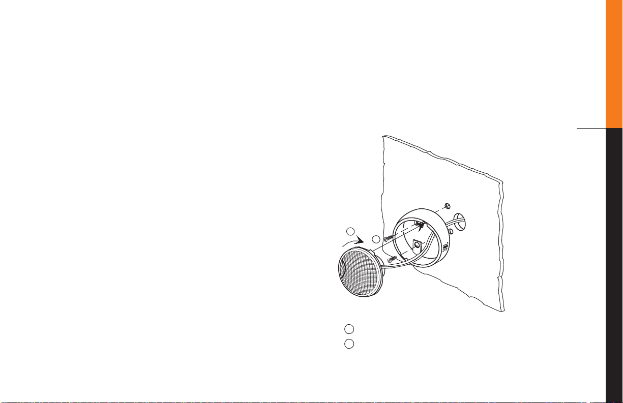
Component System Parts
ANGLE MOUNT
2
1
Line up tab with slot on bracket
Push tweeter into bracket and turn clockwise
2
1
Your new Component System
consists of the GTC04 neodymium
magnet tweeter and either a 4",
5-1/4", or 6-1/2" midwoofer. Both
the GTC04 and the midwoofer
have high-quality passive
crossover parts already built into
them. Figure 2 is an illustration
of the proper wiring procedure of
the Component System.
Tweeter Installation
The GTC04 has been supplied
with both Angle and Flush
mounting brackets. Figures 1 and
2 show the proper way to flushand angle-mount the GTC04. The
mounting hole diameter for the
flush-mount frame is 1-3/4".
Important Paperwork
Before proceeding, be sure to put
the sales receipt from your JBL
Component System purchase in a
safe place. It is necessary to validate your Limited Warranty.
Having access to the receipt is
also valuable for insurance purposes and when it comes time to
resell your vehicle.
Figure 1
03
Page 4
04
2
1
FLUSH MOUNT
Line up tab with slot on bracket
1
Push tweeter into bracket and
2
turn clockwise
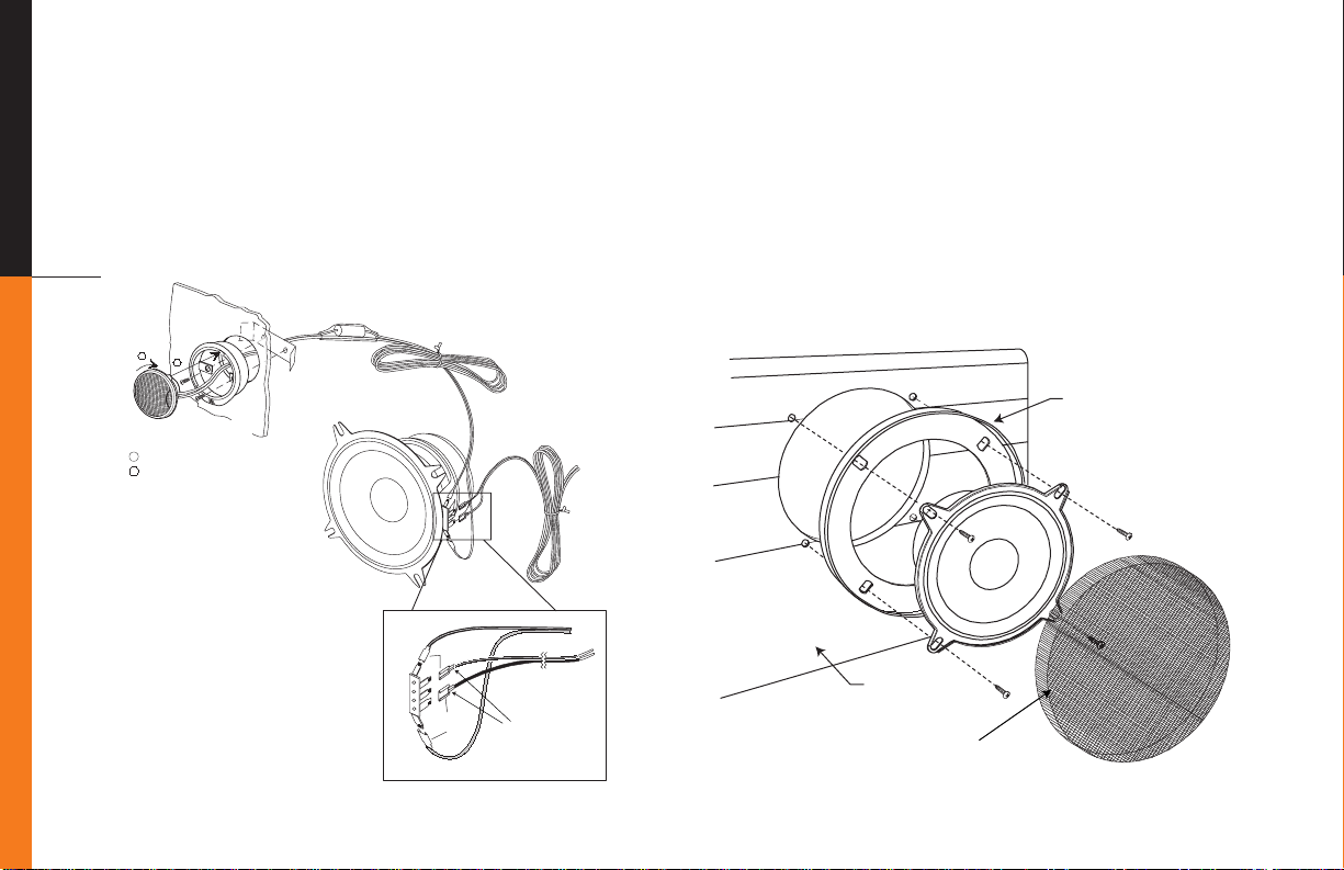
IN-LINE CROSSOVER
(DO NOT CUT OR BYPASS)
Figure 2
GTC04 WIRING HARNESS
Lead from GTC04 tweeter
Small 0.11"
(-) Terminals
Large 0.25"
(+) Terminals
Midwoofer Terminal Block
Attach to
two outermost tabs
CONNECT
TO
AMPLIFIER
Connect
to
Amplifier
or
head unit
Typical installation of the GT4.0c and GT5.0c
woofers with grilles as shown in Figure 2a.
Trim Ring
Car Door
Grille Screen
Figure 2a. Grille mounting
Page 5
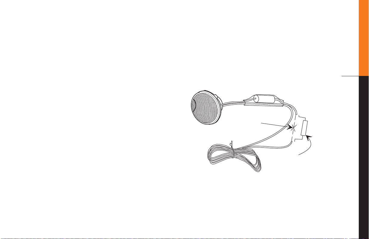
Tweeter Output Level
IN-LINE CROSSOVER
(mylar capacitor)
4 ohms /
5 watt (min)
resistor
(sold separately)
cut wire here
after capacitor
The GTC04 is a very efficient
tweeter. If there is a need to
lower the tweeter output level,
a pair of 4 ohm / 5 watt resistors
can be connected in series with
the GTC04 as shown in Figure 3.
To avoid short circuits, make
sure that heat-shrink tubing or
electrical tape is used to cover all
exposed wiring.
The in-line crossover acts as a
high-pass filter as well as a protection device that keeps the
tweeter from being over-exerted
by low frequencies that it was not
designed to reproduce. Under
normal circumstances this
crossover should not be bypassed
or removed for any reason.
Bypass the installed capacitor
only when using an outboard
active crossover or a custombuilt passive crossover set above
5kHz.
05
Figure 3
Page 6

06
Removable Mounting Ears on
GT4.0c
Bend up and down repeatedly
to break off or use tin snips.
• Some Toyota installations may require mounting ears to be removed from opposite sides.
• Some European car installations may require all four ears to be removed.
Mounting Ears Removed
Installation of the GT4.0c woofer as shown in Figures 4a and 4b.
Figure 4a
Figure 4b
Two-Screw Mounting Configuration
Page 7

Figure 5a
Mounting
Hooks
Foam
Gasket
Front View
Mounting
Slots
Mounting
Ring
Rotate
to
Lock
Installation of the GT6.0c woofer
with the Intermount II (pat. pend.)
mounting system is shown in
Figures 5a, b, c.
Rotate
to Lock
Slots for
Mounting
Hooks
Rotate
to Lock
Mounting
Hooks
Mounting for US 6-1/2"
Honda/Toyota
Factory Location
Foam
Gasket
Rear View
Mounting
Ring
Figure 5b
Figure 5c
Hole Cutout
Grille
Trim Ring
Grille
Screen
Custom Door Mounting with Grille
Screw Patterns Fit DIN (European)
165/170mm Mounting Holes
Match Notch on
Speaker with
Notch on Trim Ring
07
Page 8

08
Figure 5d
Hole Cutout
Mounting
Surface
Mounting the GT6.0c woofer in
165/170mm DIN (European)
installations using the Intermount II
Clips
clips shown in Figures 5d and 5e.
Figure 5e
Front Mounting
Rear Mounting
Page 9

Component Placement
Because of the JBL Component
System’s small size and extremely versatile mounting
options, there are an almost infinite number of placement options
to achieve excellent sound quality
in any vehicle. Please consider
the following statements to help
you get the most from your
system.
1. The most spacious stereo
image is achieved when the left
and right speaker systems are
placed as wide apart as possible.
2. The best center image will be
achieved when the distance from
the left speaker and the right
speakers are as equal as possible from your listening position.
This is most easily achieved by
placing the speakers as far forward as possible.
3. Treble is directional in nature.
This means that high frequencies
are reduced as you move off the
tweeter's axis. The angle mounts
will allow the GTC04 tweeters to
be pointed across the car to the
listener on the opposite side. This
will make each listener slightly
off-axis to the tweeter that is
closest to that listener, which
helps to compensate for the fact
that the listener is always closer
to one tweeter than to the other
(see Figure 6).
The best system integration is
achieved when the tweeter is
mounted close to the midwoofer
speaker. This helps smooth the
transition from the midrange and
tweeter crossover point.
Choosing mounting locations
which satisfy all of the above criteria will provide the most satisfying performance.
09
Figure 6
Page 10

10
++
Left
Right
Left
Channel
Right
Channel
In-line
Capacitor
–
GTC04
Tweeters
––
GTC Component System
connected to speaker outputs of
a High-Powered Head Unit
GTC
Midwoofers
–
–
++––
Left Right
Left
Channel
Right
Channel
In-line
Capacitor
–
GTC04 Connected to GTC Midwoofer,
GTC Midwoofer Connected to Amplifier
GTC04
Tweeters
--
GTC
Midwoofers
Amplifier output
set at Full Range or
High Passed at f > 80Hz
–
–
There are a variety of system
options available with the
Component System. The simplest
configuration is to use them full
range with their built-in passive
crossovers by connecting them to
the output of a head unit or an
amplifier (Figures 7 and 8).
If you want to build your system
using active (electronic)
crossovers, with separate amplifiers to drive the tweeter and
midwoofers, you can bypass the
capacitor on the tweeter and the
coil on the midwoofer (Figure 9).
A more advanced system design
can be achieved by adding a GT,
GTx, GTi, or equivalent subwoofer to your component system. In this case the component
system will be used as high and
midbass frequency drivers and
System Design
should have their extremely low
frequencies blocked by electrical
means. Active or passive crossovers can be used in order to
achieve the best system fidelity
and widest dynamic range. Crossover frequency recommendations
are given in the Specifications.
Figure 7
Figure 8
Page 11

–
+
–
Left
Left
Channel
GTC04 and GTC Midwoofer Connected
Directly to Amplifier
Electronic
Crossover
Right
Amp for
Tweeters
f > 5khz
Amp for
Woofers
f < 5khz
Hi-PassLo-Pass
Right
Channel
GTC04
Tweeters
GTC
Midwoofers
Figure 9
Installation Warnings
and Tips
• Be careful not to cut or drill
into fuel tanks, fuel lines, brake
or hydraulic lines, vacuum lines
or electrical wiring when working on your vehicle. Inspect
behind panels before you cut or
drill.
• Make sure that the midwoofer
will physically fit in the mounting location. If door mounting,
check for adequate clearance
with the window in both rolled-up
and rolled-down positions as well
as for interference with window
crank and power window mechanism. If mounting elsewhere,
check for clearance around rear
deck torsion bars, glove box or
other structural elements.
• Do not mount speakers where
water may splash on the cones.
• Make sure that it will be easy to
run connecting wires to the
speakers. Trace speaker wire
paths before you undertake
mounting.
• Always disconnect the ground
wire from the battery before
doing any work on the vehicle.
CAUTION: Fuel tanks are
located directly beneath the rear
deck in some cars. Check for
adequate speaker basket clearance before considering this
location!
11
Page 12

12
A Note on Power
Handling
As a result of their high efficiency, all JBL loudspeakers will
produce reasonable volume levels
in the automotive environment
using very little amplifier power.
However, the use of a small
amplifier to attain very high volume levels could lead to overdriving the amplifier. This will
generate high distortion levels
which can easily damage loudspeakers, even if the rated power
of the amplifier is below the rated
maximum power handling of the
loudspeaker!
As a general rule, do not turn up
the volume control past the point
where you hear distortion in the
form of either signal distortion
from an overdriven amplifier or
mechanical noise from an overstressed speaker.
For the best performance and
system reliability, you should
select an amplifier with an output
rating greater than the maximum
power likely to be used to generate the desired volume levels.
If you want your system “Loud
Clear,” we suggest that you step
up to a JBL power amplifier
which has an RMS power rating
equal to, but not exceeding the
Maximum Recommended
Amplifier Power listed in the
specifications of your specific
JBL speaker. This margin of
reserve power will ensure that
the amplifier will not attempt to
deliver more power than its
design allows. Your dealer will be
happy to point out which high
power JBL amplifiers are optimum for your application and
listening habits.
Following these guidelines will
provide virtually distortion-free
sound reproduction and long loudspeaker life.
+
WARNING: Playing loud music
over 120dB can permanently
damage your hearing. The maximum volume levels achievable
with JBL components and high
power amplification may exceed
safe levels for extended listening.
When listening at high volume
levels, always use hearing protection or turn it down!
Page 13

Specifications
Component Systems
Model GT6.0c GT5.0c GT4.0c
Grand Touring Automotive Grand Touring Automotive Grand Touring Automotive
6-1/2" 2-way Component 5-1/4" 2-way Component 4" 2-way Component
System System System
1" Titanium Composite 1" Titanium Composite 1" Titanium Composite
Balanced-Drive Neodymium Balanced-Drive Neodymium Balanced-Drive Neodymium
Magnet Tweeter with 1/2" Magnet Tweeter with 1/2" Magnet Tweeter with 1/2"
Dome. Surface and Flush Dome. Surface and Flush Dome. Surface and Flush
Mounting Brackets Supplied Mounting Brackets Supplied Mounting Brackets Supplied
Graphite-Reinforced Graphite-Reinforced Graphite-Reinforced
Polytex Woofer Cone Polytex Woofer Cone Polytex Woofer Cone
with Butyl Rubber Surround with Butyl Rubber Surround with Butyl Rubber Surround
Speaker Impedance 4 Ohms 4 Ohms 4 Ohms
Recommended Amplifier 5 – 125 Watts RMS 5 – 110 Watts RMS 5 – 100 Watts RMS
Power Range
Frequency Response 50Hz – 21kHz 60Hz – 21kHz 70Hz – 21kHz
Sensitivity 91dB 90dB 90dB
Mounting Depth
Drop In: 2-3/16" 2-3/8" 1-3/8"
Bottom Mount: 2-9/16" 2-1/2" 2"
13
Page 14

Warranty Terms:
1 Year Transferable Limited Warranty / 2 Year Extended Transferable Limited Warranty (USA Only)
14
This is an important document.
Attach your bill of sale to this
page and keep it in a safe place.
Your bill of sale is your warranty.
The JBL warranty remains in
effect for one year from the date
of the first consumer purchase
unless installed by an authorized
JBL dealer. Installation by an
authorized JBL dealer will extend
the warranty to a period of two
years.
Who is Protected by this Warranty
The JBL warranty protects the
original owner and all subsequent
owners providing that the JBL
product was purchased from an
authorized dealer in the United
States or purchased by military
personnel from an authorized
military outlet. A copy of the
original dated bill of sale must be
presented whenever warranty
service is required.
What is Covered by this Warranty
Except as specified below, the JBL
warranty covers all defects in
material and workmanship. The
following are not covered: Damage
caused by accident, misuse, abuse,
product modification or neglect;
damage occurring during shipment; damage from failure to
follow instructions contained in
the instruction manual; damage
resulting from the performance of
repairs by someone not authorized
by JBL; damage caused by installation of parts that do not conform
to JBL specifications; units used for
commercial or business use; any
claims based on misrepresentations by the seller; products sold on
an “as-is” or final sale basis; or the
cost of installing, removing, or
reinstalling the unit. JBL’s liability
is limited to the repair or replacement, at our option, of any
defective product and shall not
include incidental or consequential
damages. JBL reserves the right
to replace a discontinued model
with a comparable model. Any
replacement units or parts may
be new or rebuilt.
To Obtain Warranty Service
If you require warranty service,
please return the product to your
dealer. If this is not possible and
you live in the United States,
please call 1-800-336-4JBL, for
information on how to obtain
service or replacement.
If purchased outside the United
States, contact your local dealer
for repair or replacement.
Do Not Return Products to the JBL
Factory without Authorization.
They will be Returned Unopened.
You are responsible for transporting your product for repair or
replacement. JBL will pay reasonable return charges for delivery
to any location in the United States
if the repair or replacement is
covered under the warranty.
Correspondence with JBL should be
addressed to: JBL Customer
Service, 80 Crossways Park West,
Woodbury, NY 11797 or fax us at
516-496-0812. Outside the United
States, please contact your local
distributor.
This warranty gives you specific
legal rights. You may also have
other rights which vary from state
to state. Some states do not allow
the exclusion or limitation of
incidental or consequential
damages or limitations on how long
an implied warranty lasts, so the
above may not apply to you.
Page 15

15
Page 16

Declaration of Conformity
A Harman International Company
C
E
L
E
B
R
A
T
I
N
G
5
0
Y
E
A
R
S
We, JBL Europe A/S
Kongevejen 194B
DK-3460 Birkerød
DENMARK
declare in own responsibility, that the products
described in this owner’s manual are in compliance
with technical standards:
EN 50 081-1/1992
EN 50 082-1/3.1995
Steen Michaelsen
JBL Europe A/S
Birkerød. DENMARK. 5/96
JBL Consumer Products, Inc.
80 Crossways Park West
Woodbury, NY 11797
8500 Balboa Blvd.
Northridge, CA 91329
800-336-4JBL (4525)
Part No. GT405060OM
Made in China
 Loading...