

Page 1

TM
TM
ESC550
simple
setup guide
Page 2

thank you for choosing JBL. For over 50
years, JBL has been involved in every aspect of
musical and film recording and reproduction,
from live performances to monitoring the
recordings you play in your home, car, or office.
We’re confident that the
have chosen will provide every note of enjoyment that you expected – and that when you
think about purchasing additional audio equipment for your home, car, or office, you will once
again choose JBL.
Please take a moment to complete the enclosed
profile card. It enables us to keep you posted on
our latest advancements, and helps us to better
understand our customers and build products
that meet your needs and expectations.
JBL Consumer Products
JBL system you
Table of Contents
Safety Precautions . . . . . . . . . . . . . . . . . . . . . . . . . . . . . . . . . . . . . . . . . . . . . . . . . 3
1. Speaker Placement . . . . . . . . . . . . . . . . . . . . . . . . . . . . . . . . . . . . . . . . . . . . . . 5
Mounting Options . . . . . . . . . . . . . . . . . . . . . . . . . . . . . . . . . . . . . . . . . . . . . . . 5
2. Connections . . . . . . . . . . . . . . . . . . . . . . . . . . . . . . . . . . . . . . . . . . . . . . . . . . . 6
Connect TV or VCR to The Source™ . . . . . . . . . . . . . . . . . . . . . . . . . . . . . . . . . 6
Connect Antennas to The Source . . . . . . . . . . . . . . . . . . . . . . . . . . . . . . . . . . 6
Connect Optional Cassette Deck to The Source . . . . . . . . . . . . . . . . . . . . . . . . . 6
Connect The Source to a Subwoofer . . . . . . . . . . . . . . . . . . . . . . . . . . . . . . . . 6
Speaker Connection Tips . . . . . . . . . . . . . . . . . . . . . . . . . . . . . . . . . . . . . . . 7
Remote Control Battery Installation . . . . . . . . . . . . . . . . . . . . . . . . . . . . . . . . 7
3. Operation . . . . . . . . . . . . . . . . . . . . . . . . . . . . . . . . . . . . . . . . . . . . . . . . . . . 8
Volume . . . . . . . . . . . . . . . . . . . . . . . . . . . . . . . . . . . . . . . . . . . . . . . . . . 8
Mute . . . . . . . . . . . . . . . . . . . . . . . . . . . . . . . . . . . . . . . . . . . . . . . . . . . 8
Bass . . . . . . . . . . . . . . . . . . . . . . . . . . . . . . . . . . . . . . . . . . . . . . . . . . . 8
Treble . . . . . . . . . . . . . . . . . . . . . . . . . . . . . . . . . . . . . . . . . . . . . . . . . . . 8
CD Operation . . . . . . . . . . . . . . . . . . . . . . . . . . . . . . . . . . . . . . . . . . . . . . . . . 11
To Skip to a Different Track . . . . . . . . . . . . . . . . . . . . . . . . . . . . . . . . . . . . 11
To Scan Within the Same Track . . . . . . . . . . . . . . . . . . . . . . . . . . . . . . . . . . 11
To Pause the CD . . . . . . . . . . . . . . . . . . . . . . . . . . . . . . . . . . . . . . . . . . . . 11
To Stop the CD . . . . . . . . . . . . . . . . . . . . . . . . . . . . . . . . . . . . . . . . . . . . . 11
To Play the Tracks of a CD in Random Order . . . . . . . . . . . . . . . . . . . . . . . . . . 12
To Repeat the Disc . . . . . . . . . . . . . . . . . . . . . . . . . . . . . . . . . . . . . . . . . . 12
Tuner Operation . . . . . . . . . . . . . . . . . . . . . . . . . . . . . . . . . . . . . . . . . . . . . . . 12
To Switch Between AM and FM . . . . . . . . . . . . . . . . . . . . . . . . . . . . . . . . . . 12
To Tune to a Particular Station . . . . . . . . . . . . . . . . . . . . . . . . . . . . . . . . . . 12
If a Selected FM Station is a Little Noisy . . . . . . . . . . . . . . . . . . . . . . . . . . . . 14
To Have the Tuner Search for the Next Strong Station . . . . . . . . . . . . . . . . . . . 14
Preset Operation . . . . . . . . . . . . . . . . . . . . . . . . . . . . . . . . . . . . . . . . . . . . . . . 14
Surround Mode Operation . . . . . . . . . . . . . . . . . . . . . . . . . . . . . . . . . . . . . . . . . 17
Test Tone . . . . . . . . . . . . . . . . . . . . . . . . . . . . . . . . . . . . . . . . . . . . . . . . . . 18
Balance . . . . . . . . . . . . . . . . . . . . . . . . . . . . . . . . . . . . . . . . . . . . . . . . . 18
Center Channel Volume . . . . . . . . . . . . . . . . . . . . . . . . . . . . . . . . . . . . . . . 18
Rear Channel Volume . . . . . . . . . . . . . . . . . . . . . . . . . . . . . . . . . . . . . . . . . 20
Delay Time . . . . . . . . . . . . . . . . . . . . . . . . . . . . . . . . . . . . . . . . . . . . . . . 20
Troubleshooting . . . . . . . . . . . . . . . . . . . . . . . . . . . . . . . . . . . . . . . . . . . . . . . . . . 22
Specifications . . . . . . . . . . . . . . . . . . . . . . . . . . . . . . . . . . . . . . . . . . . . . . . . . . 23
Page 3
read first! Important Safety Precautions!
CAUTION
RISK OF ELECTRIC SHOCK
DO NOT OPEN
CAUTION: To prevent electric shock,
do not remove the grounding plug
on the power cord, or use any plug
or extension cord that does not have
a grounding plug provided.
Make certain that the
AC outlet is properly grounded.
Do not use an adapter plug
with this product.
The lightning flash with arrowhead
symbol, within an equilateral triangle,
is intended to alert the user to the
presence of uninsulated “dangerous
voltage” within the product’s enclosure
that may be of sufficient magnitude to
constitute a risk of electric shock to
persons.
The exclamation point within an
equilateral triangle is intended to alert
the user to the presence of important
operating and maintenance (servicing)
instructions in the literature
accompanying the appliance.
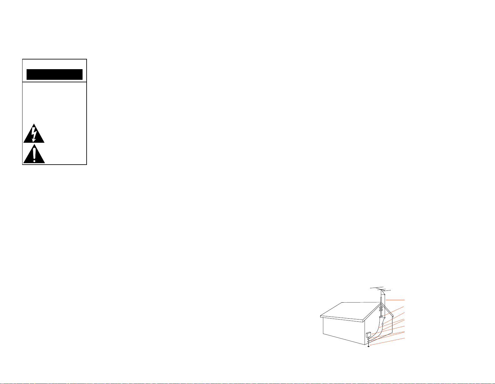
Antenna Lead-In Wire
Ground Clamp
Antenna Discharge Unit (NEC Section 810-20)
Grounding Conductors (NEC Section 810-21)
Electric Service Equipment
Ground Clamps
Power Service Grounding Electrode System
(NEC Art 250, Part H)
1. Read Instructions. All the
safety and operating instructions should be read before
the product is operated.
2. Retain Instructions. The
safety and operating instructions should be retained for
future reference.
3. Heed Warnings. All warn-
ings on the product and in the
operating instructions should
be adhered to.
4. Follow Instructions. All
operating and use instructions
should be followed.
5. Cleaning. Unplug this prod-
uct from the wall outlet before
cleaning. Do not use liquid
cleaners or aerosol cleaners.
Use a damp cloth for cleaning.
6. Attachments. Do not use
attachments not recommended
by the product manufacturer,
as they may cause hazards.
7. Water and Moisture. Do
not use this product near
water – for example, near a
bathtub, wash bowl, kitchen
sink or laundry tub; in a wet
basement; or near a swimming
pool; and the like.
8. Accessories. Do not place
this product on an unstable
cart, stand, tripod, bracket, or
table. The product may fall,
causing serious injury to a
child or adult, and serious
damage to the product. Use
only with a cart, stand, tripod,
bracket, or table recommended
by the manufacturer, or sold
with the product. Any mounting of the product should follow the manufacturer’s instructions, and should use a
mounting accessory recommended by the manufacturer.
9. A Product and Cart
Combination Should Be
Moved with Care. Quick stops,
excessive force, and uneven
surfaces may cause the product and cart combination to
overturn.
10. Ventilation. Slots and
openings in the cabinet are
provided for ventilation and to
ensure reliable operation of
the product and to protect it
from overheating, and these
openings must not be blocked
or covered. The openings
should never be blocked by
placing the product on a bed,
sofa, rug, or other similar surface. This product should not
be placed in a built-in installation such as a bookcase or
rack unless proper ventilation
is provided or the manufacturer’s instructions have been
adhered to.
11. Power Sources. This prod-
uct should be operated only
from the type of power source
indicated on the marking
label. If you are not sure
of the type of power supply
to your home, consult your
product dealer or local power
company.
For products intended
to operate from battery power,
or other sources, refer to the
operating instructions.
12. Grounding or
Polarization. This product may
be equipped with a polarized
alternating-current line plug
(a plug having one blade
wider than the other). This
plug will fit into the power
outlet only one way. This is a
safety feature. If you are
unable to insert the plug fully
into the outlet, try reversing
the plug. If the plug should
still fail to fit, contact your
electrician to replace your
obsolete outlet. Do not defeat
the safety purpose of the
polarized plug.
13. Power-Cord Protection.
Power-supply cords should be
routed so that they are not
likely to be walked on or
pinched by items placed upon
or against them, paying particular attention to cords at
plugs, convenience receptacles, and the point where they
exit from the product.
14. Nonuse Periods. The
power cord of the product
should be unplugged from the
outlet when left unused for
long periods of time.
15. Outdoor Antenna
Grounding. If an outside
antenna or cable system is
connected to the product, be
sure the antenna or cable system is grounded so as to provide some protection against
voltage surges and built-up
static charges. Article 810 of
the National Electrical Code,
ANSI/NFPA 70, provides information with regard to proper
grounding of the mast and
supporting structure, grounding of the lead-in wire to an
antenna discharge unit, size of
grounding conductors, location
of antenna-discharge unit,
connection to grounding electrodes, and requirements for
the grounding electrode. See
Figure 1.
16. Lightning. For added pro-
tection for this product during
a lightning storm, or when
it is left unattended and
unused for long periods of
time, unplug it from the wall
outlet and disconnect the
antenna or cable system. This
will prevent damage to the
product due to lightning and
power-line surges.
17. Power Lines. An outside
antenna system should not be
located in the vicinity of
overhead power lines or other
electric light or power circuits,
or where it can fall into such
power lines or circuits. When
installing an outside antenna
system, extreme care should
be taken to keep from touching
such power lines or circuits, as
contact with them might be
fatal.
18. Overloading. Do not over-
load wall outlets, extension
cords, or integral convenience
receptacles, as this can result
in a risk of fire or electric
shock.
19. Object and Liquid Entry.
Never push objects of any kind
into this product through
openings, as they may touch
dangerous voltage points or
short-out parts that could
result in a fire or electric
shock. Never spill liquid of
any kind on the product.
– 3 –
20. Servicing. Do not attempt
to service this product yourself, as opening or removing
covers may expose you to
dangerous voltage or other
hazards. Refer all servicing to
qualified service personnel.
21. Damage Requiring
Service. Unplug this product
from the wall outlet and refer
servicing to qualified service
personnel under the following
conditions:
a. The power-supply cord or
the plug has been damaged; or
b. Objects have fallen onto, or
liquid has been spilled into,
the product; or
c. The product has been
exposed to rain or water; or
d. The product does not oper-
ate normally when following
the operating instructions.
Adjust only those controls that
are covered by the operating
instructions, as an improper
adjustment of other controls
may result in damage and will
often require extensive work
by a qualified technician to
restore the product to its
normal operation; or
e. The product has been
dropped or damaged in any
way; or
Figure 1.
Example of Antenna Grounding as
per National Electrical Code,
ANSI/NFPA 70
f. The product exhibits a dis-
tinct change in performance –
this indicates a need for
service.
22. Replacement Parts. When
replacement parts are required,
be sure the service technician
has used replacement parts
specified by the manufacturer
or that have the same characteristics as the original part.
Unauthorized substitutions
may result in fire, electric
shock or other hazards.
23. Safety Check. Upon
completion of any service or
repairs to this product, ask the
service technician to perform
safety checks to determine
that the product is in proper
operating condition.
24. Wall or Ceiling Mounting.
The product should be
mounted to a wall or ceiling
only as recommended by the
manufacturer.
25. Heat. The product should
be situated away from heat
sources such as radiators, heat
registers, stoves, or other
products (including amplifiers)
that produce heat.
Part No. JBLULB 6/96
Page 4
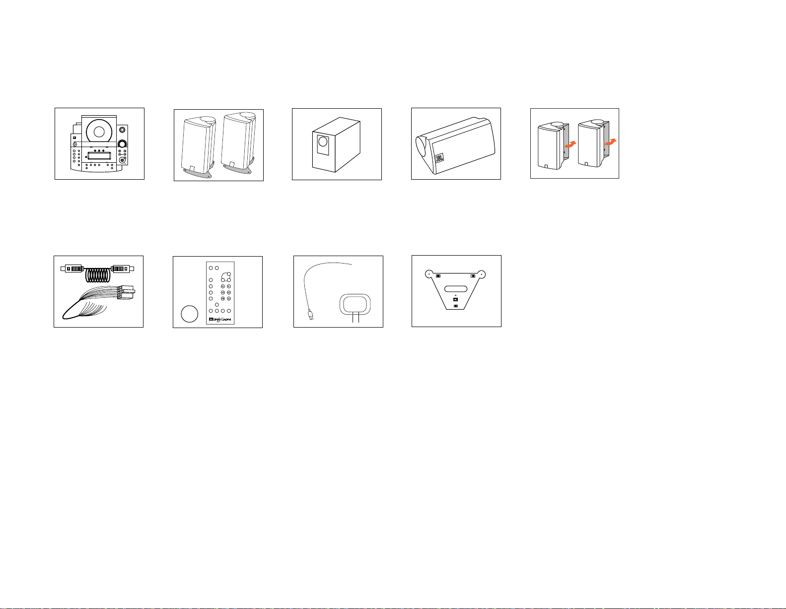
included
CD
Open
Random
Power
Volume
Skip
Search
Tune
Stereo/Mono
– Bass +
Surround Mode
– Treeble + Tuner Presets
Auto Add
Tape/Aux
TV Auto Tune
AM/FM Repeat
Delete
Rear
Speakers
TM
Mute
Volume
CD
AM/FM
TV
Aux
Surround
Tone
Calibrate
Power Sleep
+–
+–
+
CR
2025
Source cable
Speaker cable
harness
FM antenna
AM antenna
The Source.
Cables.
features
• Built-in CD player with
– Random play
– Repeat play
– 8x oversampling
• AM/FM tuner with
– 32 presets
– Auto-preset function
Two sat10/550 front
satellite speakers
(with removable shelf stands
and wall-mounting brackets).
Remote with battery.
• 250 watts total
amplification
– 100 watts – subwoofer
– 35 watts each front
channel
– 23 watts each surround
channel
Powered subwoofer containing
all amplification.
FM and AM antennas.
• 2-way front satellite
speakers with 3/4" titanium
composite dome highfrequency drivers
• Powered bass reflex
subwoofer with 2 x 6-1/2"
woofers
One sat10/550 center speaker.
Wall bracket for Source.
• Adjustable, removable wallmounting brackets for all
speakers
• Video-shielded front satellite
speakers
• Recessed wire channels on
satellites and surrounds
One pair of sat10 surround
speakers with removable wallmounting brackets.
– 4 –
Page 5

5
– 6 ft.
one. Speaker Placement
0-2 ft.
Satellites
Mounting Options
Front
On shelves. Shelf stands
included.
On the wall. Brackets and
hardware included.
Subwoofer
On optional stands.
Part No. FS10/20.
FS10/20WHT (white).
Surround Speakers
Surrounds
hardware included.
On shelves. Wall-mounted. Brackets and
On optional stands.
– 5 –
Page 6
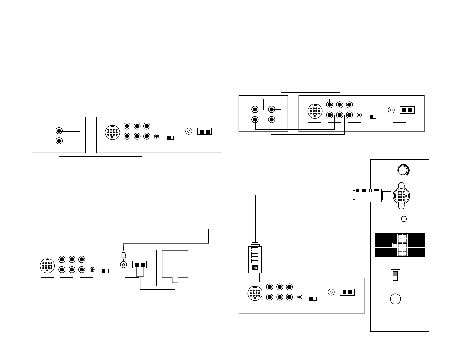
two. Connections
JBL ESC550
Powered Subwoofer
Out
In
A or B
TV
Tape/Aux
AM
Loop
US Europe
Tuner
Frequency
Standard
Rear Panel of The Source
TV or Hi-Fi VCR
Antenna
FM
75Ω
L
R
L
R
AUDIO OUT
JBL ESC550
Powered Subwoofer
Out
In
A or B
TV
Tape/Aux
AM
Loop
US Europe
Tuner
Frequency
Standard
Antenna
FM
75Ω
L
R
FRONT
SPEAKERS
+–
+–
SURROUND
SPEAKERS
LEFT
RIGHT
AC
120V
˜
60Hz
575W
MAIN
POWER
POWER
INPUT
SUBWOOFER
LEVEL
FUSE
ON
OFF
LEFT
CENTER
RIGHT
CAUTION:
FOR CONTINUED PROTECTION
AGAINST RISK OF FIRE
REPLACE WITH SAME
TYPE T 8A/250V FUSE.
ATTENTION:
UTILISER UN FUSIBLE DE
RECHANGE DE MEME
TYPE T 8A/250V.
CAUTION:
DISCONNECT SUPPLY CORD
BEFORE CHANGING FUSE.
ATTENTION:
DEBRANCHER AVANT DE
REMPLACER LE FUSIBLE.
Rear Panel of The Source
Rear Panel of Subwoofer
JBL ESC550
Powered Subwoofer
Out
In
A or B
TV
Tape/Aux
AM
Loop
AM
Antenna
FM Antenna
US Europe
Tuner
Frequency
Standard
Antenna
FM
75Ω
L
R
Rear Panel of The Source
JBL ESC550
Powered Subwoofer
Out
In
A or B
TV
Tape/Aux
AM
Loop
US Europe
Tuner
Frequency
Standard
Rear Panel of The SourceCassette Deck
Antenna
FM
75Ω
L
R
L
R
OUT
L
R
IN
The ESC550 System’s Main
Power Switch, located on the
Subwoofer, must be “Off”
when making any connections.
After all connections are com-
pleted the Main Power Switch
should be set to “On” and
remain “On” at all times
unless the user is going on an
extended vacation or changing
Connect TV or VCR to The Source
Note: The Source also provides
a stereo mini-jack (B) to provide an easy connnection to
devices that have a stereo
mini-jack audio output.
Connect Antennas to The Source
the connections.
The Source’s “Power” button
will be used to turn the system on and off during normal
operation.
Connect Optional Cassette Deck to The Source
Connect The Source to a Subwoofer
– 6 –
Page 7
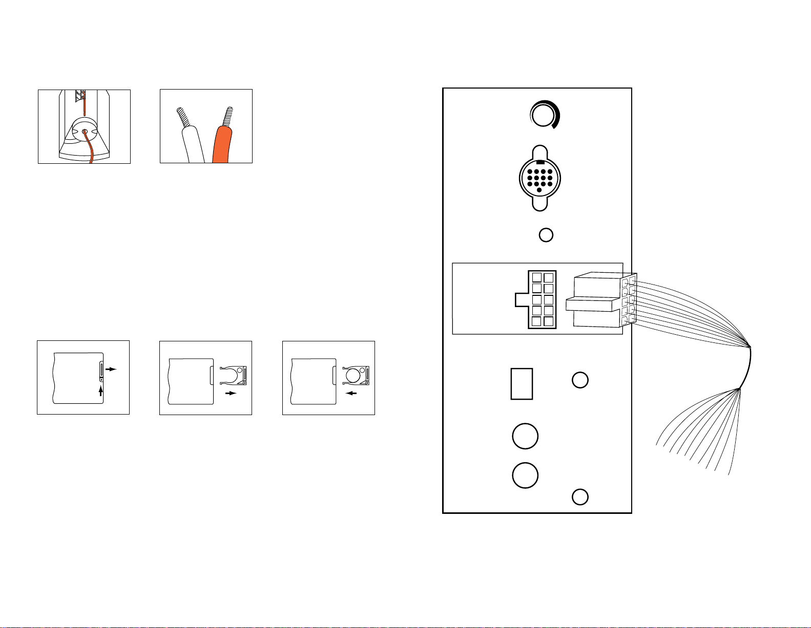
Speaker Connection Tips
Front
Speakers
+–
+–
Surround
Speakers
AC
120V
˜
60Hz
575W
MAIN
POWER
POWER
INPUT
SUBWOOFER
LEVEL
FUSE
ON
OFF
CAUTION:
FOR CONTINUED PROTECTION
AGAINST RISK OF FIRE
REPLACE WITH SAME
TYPE T 8A/250V FUSE.
ATTENTION:
UTILISER UN FUSIBLE DE
RECHANGE DE MEME
TYPE T 8A/250V.
CAUTION:
DISCONNECT SUPPLY CORD
BEFORE CHANGING FUSE.
ATTENTION:
DEBRANCHER AVANT DE
REMPLACER LE FUSIBLE.
+
+
+
For satellites, thread speaker
wire through the hole in the
bottom of the speaker, then
feed it through the recessed
wire channel.
Separate and strip the ends of
the speaker wire as shown.
Speakers and electronics terminals have corresponding “+”
and “–” terminals. It is important to connect both speakers
identically: “+” on the speaker
Remote Control Battery Installation
Push small tab towards
battery slot and pull battery
drawer out.
Remove old battery.
to “+” on the amplifier and
“–” on the speaker to “–” on
the amplifier. Wiring “out of
phase” results in thin sound,
weak bass and a poor stereo
image.
Insert new battery with “+”
side up, and slide battery
drawer back into remote.
The speaker cables are clearly
labeled for proper hook up to
the corresponding speaker.
Connect the “+” portion of the
cable to the red terminal on
the speaker and the “–”
portion of the cable to the
black terminal on the speaker.
– 7 –
Page 8
three. Operation
Mute
Volume
+–
– Bass +
Surround Mode
– Treble
+
– Treble +
Volume
– Bass +
Surround Mode
– Treble
+
– Treble +
Mute
Volume
+–
Volume
Mute
+–
Volume
Surround
Calibrate
+–
Surround
Calibrate
+–
Surround
Calibrate
+–
Surround
Calibrate
+–
Volume
Mute
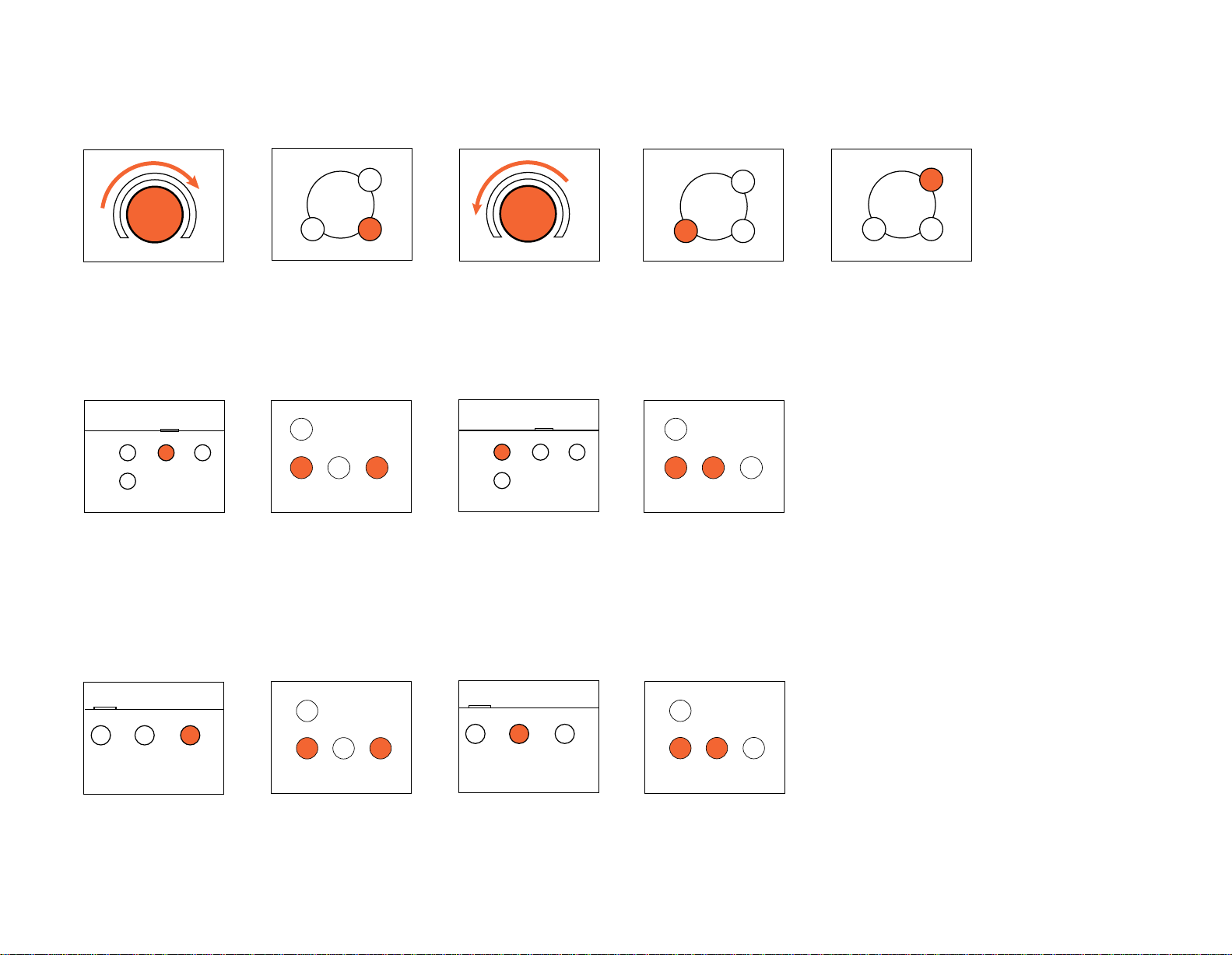
To raise volume: Turn control
on The Source clockwise or
Bass
To raise the bass level: Push
“+” on The Source or
Treble
push “+” on the remote
control.
push “Calibrate” on the
remote control until “Bass”
illuminates in The Source display. Push “+” until you reach
the desired level.
To lower volume: Turn volume
control on The Source
counterclockwise or
To lower the bass level: Push
“–” on The Source or
push “–” on the remote
control.
push “Calibrate” on the
remote control until “Bass”
illuminates in The Source
display.
Push “–” until you reach the
desired level.
To lower volume completely:
Push “Mute” on the remote
control. When “Mute” is
pushed again, the volume will
return to its original level.
To raise the treble level: Push
“+” on The Source or
push “Calibrate” on the
remote control until “Treble”
illuminates in The Source display. Push “+” until you reach
the desired level.
To lower the treble level: Push
“–” on The Source or
push “Calibrate” on the
remote control until “Treble”
illuminates in The Source display. Push “–” until you reach
the desired level.
– 8 –
Page 9

CD
Open
Random
Power
Volume
Skip
Search
Tune
Stereo/Mono
– Bass +
Surround Mode
– Treble + Tuner Presets
Auto Add
Tape/Aux
TV Auto Tune
AM/FM Repeat
Delete
Rear
Speakers
TM
Mute
Volume
CD
AM/FM
TV
Aux
Surround
Tone
Calibrate
Power Sleep
+–
+–
The Source
Remote Control
– 9 –
Page 10

CD
Open
Random
Power
Volume
Skip
Search
Tune
Stereo/Mono
– Bass +
Surround Mode
– Treble + Tuner Presets
Auto Add
Tape/Aux
TV Auto Tune
AM/FM Repeat
Delete
Rear
Speakers
TM
Mute
Volume
CD
AM/FM
TV
Aux
Surround
Tone
Calibrate
Power Sleep
+–
+–
The Source
Remote Control
– 10 –
Page 11

CD Operation
Open
Power
Volume
Search
Tune
AM/FM
TV
Aux
Skip
Search
Tune
Search
Tune
Search
Tune
TV
Aux
Surround
Skip
Search
Tune
AM/FM
TV
Aux
TV
Aux
Surround
TV
Aux
Surround
1. Push “Power” and/or
“Open” on The Source.
2. Insert CD.
To Skip to a Different Track:
Push “Back” or “Forward,” on
The Source or
To Pause the CD:
3. Push “Play” on The Source
or
the remote control, until the
number of the desired track
appears on the display.
the remote control. (The door
will close automatically.)
To Scan Within the Same Track:
Push left arrow or right arrow
on The Source or
the remote control.
To Stop the CD:
Push “Pause” on The Source or the remote control.
Push “Stop” on The Source or the remote control.
Push again to resume play.
– 11 –
Page 12

To Play the Tracks of a CD in Random Order:
CD Random
TV Auto Tune
AM/FM Repeat
CD Random
Stereo/MonoTape/Aux
TV Auto Tune
AM/FM Repeat
Power
Stereo/MonoTape/Aux
TV Auto Tune
AM/FM Repeat
Rear
Stereo/MonoTape/Aux
TV Auto Tune
AM/FM Repeat
Rear
AM/FM
TV
Aux
Mute
Volume
CD
AM/FM
Power Sleep
+
Mute
Volume
CD
AM/FM
Power Sleep
+
Skip
Search
Tune
To Repeat the Disc:
Tuner Operation
Push “Power” or “AM/FM” on
The Source or the remote
control.
Push “Random” on The Source.
The Source will automatically
delete each track it has played
from the “Random” operation.
Push “Repeat” on The Source.
Note: If “Random” and
“Repeat” are both engaged
the CD player will randomly
play the disc, deleting all
played tracks, until the disc is
finished. It will then randomly
play the disc again.
To Switch Between AM and FM:
Push “AM/FM” on The Source
or
the remote control.
To Tune to a Particular Station:
Push “<<” or “>>” on
The Source or
the remote control. To search
rapidly, hold down the “<<” or
“>>” button.
– 12 –
Page 13

CD
Open
Random
Power
Volume
Skip
Search
Tune
Stereo/Mono
– Bass +
Surround Mode
– Treble + Tuner Presets
Auto Add
Tape/Aux
TV Auto Tune
AM/FM Repeat
Delete
Rear
Speakers
TM
Mute
Volume
CD
AM/FM
TV
Aux
Surround
Tone
Calibrate
Power Sleep
+–
+–
The Source
Remote Control
– 13 –
Page 14

If a Selected FM Station is a Little Noisy:
Stereo/MonoTape/Aux
TV Auto Tune
Rear
Speakers
AM/FM
TV
Aux
Stereo/MonoTape/Aux
TV Auto Tune
AM/FM Repeat
Rear
Speakers
AM/FM
TV
Aux
Tuner Presets
Auto Add
Delete
Skip
Search
Tune
Tuner Presets
Auto Add
Delete
Tuner Presets
Auto Add
Delete
Skip
Search
Tune
Skip
Search
Tune
AM/FM
TV
Aux
To Have the Tuner Search for the Next Strong Station:
Push “Stereo/Mono” on The
Source. This will play the
selected station without any
stereo separation, but there
will be much less background
noise.
Preset Operation
1. Tune to the station that
you want to add into memory.
2. Push “Add” on The Source.
That station is now added to
your selection of stations in
memory.
The “<<” or “>>” on The
Source or
3. To delete a preset:
Push “Delete” on The Source.
That station is now removed
from your selection of stations
in memory.
the remote control will tune
up or down one frequency
at a time.
4. To skip between preset
stations: Push “|<” or “>|”
on The Source or
Push “Auto Tune” on The
Source.
the remote control.
Then when you push “<<” or
“>>” on The Source or
the remote the tuner will automatically advance to the next
station with a strong signal.
The Source has a unique feature that will automatically
place up to 32 stations in
memory.
To activate this feature, push
and hold the “Auto” button for
one second.
The tuner will search the dial
and place the stations with a
strong signal into memory.
Note: Activating this feature
will delete all stations that
were previously stored in
memory. To prevent this from
accidentally occurring, the
Auto button will only activate
if held for a full second.
– 14 –
Page 15

CD
Open
Random
Power
Volume
Skip
Search
Tune
Stereo/Mono
– Bass +
Surround Mode
– Treble + Tuner Presets
Auto Add
Tape/Aux
TV Auto Tune
AM/FM Repeat
Delete
Rear
Speakers
TM
Mute
Volume
CD
AM/FM
TV
Aux
Surround
Tone
Calibrate
Power Sleep
+–
+–
The Source
Remote Control
– 15 –
Page 16

CD
Open
Random
Power
Volume
Skip
Search
Tune
Stereo/Mono
– Bass +
Surround Mode
– Treble + Tuner Presets
Auto Add
Tape/Aux
TV Auto Tune
AM/FM Repeat
Delete
Rear
Speakers
TM
Mute
Volume
CD
AM/FM
TV
Aux
Surround
Tone
Calibrate
Power Sleep
+–
+–
The Source
Remote Control
– 16 –
Page 17

Surround Mode Operation
– Bass +
Surround Mode
Rear
Speakers
Stereo/MonoTape/Aux
Rear
Speakers
Aux
Surround
Tone
Calibrate
+–
What is Dolby*Pro Logic*?
Dolby*Pro Logic*is an
encode/decode process by
which four channels of soundtrack information are encoded
into two channels for playback
on VCRs, laser disc players,
and some TV broadcasts, and
then decoded back into four
channels for playback through
five loudspeakers. Remember
that a Dolby Pro Logic system
consists of three channels of
information for front left,
center, and right speakers and
one channel of mono surround
information. The surround
This system contains three surround modes.
1. Dolby Pro Logic – In this
mode all five speakers are
used.
3. 2-channel – In this mode
the program is played back in
a traditional stereo form.
2. Dolby Pro Logic Phantom –
In this mode the center
channel does not operate.
This may be preferred when
listening to a music source
that was not recorded with
surround channel information.
channel is played back
through two speakers. Dolby
Pro Logic helps to re-create all
of the impact and excitement
of a movie theater in your
home.
To switch between the three
surround modes: Push
“Surround Mode” on The
Source or
the remote control. If you are listening to a pro-
gram in the Dolby Pro Logic
Normal or Phantom mode
and you wish to turn off the
surround speakers:
Push “Rear Speakers” on
The Source.
– 17 –
Page 18

Test Tone
Surround
Calibrate
+–
Surround
Calibrate
+–
Surround
Calibrate
+–
Surround
Calibrate
+–
Surround
Calibrate
+–
Surround
Calibrate
+–
Aux
Surround
Tone
Calibrate
+–
For proper Dolby Pro Logic
operation, a test tone is used
to calibrate the volume settings of the speakers. A noise
will be heard cycling, in order,
from the front left, center,
right, and both surround
speakers.
Balance
Push “Calibrate” on the
remote control until “Balance”
appears in the display.
Push “+” on the remote
control to adjust the balance
toward the right speaker.
Using the remote control, push
“Tone.” Then adjust the Center
and Surround levels until the
volume of all the speakers is
the same during the test.
Note: The test tone is used to
calibrate the performance of
the system. When listening
to an actual recording, the
Push “–” on the remote
control to adjust the balance
toward the left speaker.
volume level of the surround
channels is generally much
lower than that of the front
channels. In fact, when
listening to a movie, virtually
all of the dialogue and a substantial number of the effects
are reproduced through the
center channel.
Center Channel Volume
Push “Calibrate” on the
remote control until “Center”
appears in the display and the
corresponding LED on top of
the display is lit.
Push “+” on the remote
control to increase the volume
of the center channel.
Push “–” on the remote
control to decrease the
volume of the center channel.
– 18 –
Page 19

CD
Open
Random
Power
Volume
Skip
Search
Tune
Stereo/Mono
– Bass +
Surround Mode
– Treble + Tuner Presets
Auto Add
Tape/Aux
TV Auto Tune
AM/FM Repeat
Delete
Rear
Speakers
TM
Mute
Volume
CD
AM/FM
TV
Aux
Surround
Tone
Calibrate
Power Sleep
+–
+–
The Source
Remote Control
– 19 –
Page 20

Rear Channel Volume
Surround
Calibrate
+–
Surround
Calibrate
+–
Surround
Calibrate
+–
0 5 10 15 20 25 30 35 40
40
35
30
25
20
15
10
5
0
15ms
15ms
15ms
20ms
25ms
30ms
30ms
30ms
Distance (in feet) From Front Speakers
Distance (in feet) From Rear Speakers
Preferable Acceptable
Surround
Calibrate
+–
Surround
Calibrate
+–
Surround
Calibrate
+–
Push “Calibrate” on the
remote control until “Rear”
appears in the display and the
corresponding LED on top of
the display is lit.
Push “+” on the remote control to increase the volume
of the rear channels.
Delay Time
The delay control allows the
user to set the surround delay
between 15 and 30 milliseconds in 1 millisecond increments. The best setting will
depend on the distance
between the main listening
area and the front speakers as
well as the distance between
the main listening area and
the rear speakers.
The chart at the bottom shows
the recommended settings.
Push “–” on the remote
control to decrease the
volume of the rear channels.
Push “Calibrate” on the
remote control until “Delay”
appears in the display and the
corresponding LED on top of
the display is lit.
Push “+” on the remote
control to increase the
delay time.
– 20 –
Push “–” on the remote
control to decrease the
delay time.
Page 21

CD
Open
Random
Power
Volume
Skip
Search
Tune
Stereo/Mono
– Bass +
Surround Mode
– Treble + Tuner Presets
Auto Add
Tape/Aux
TV Auto Tune
AM/FM Repeat
Delete
Rear
Speakers
TM
Mute
Volume
CD
AM/FM
TV
Aux
Surround
Tone
Calibrate
Power Sleep
+–
+–
The Source
Remote Control
– 21 –
Page 22

Troubleshooting
If there is no sound from any
of the speakers, check the
following:
• Make sure the subwoofer is
plugged into an active AC wall
outlet.
• Make sure the Master Power
Switch, located on the rear of
the subwoofer, is in the
“On/Standby” position.
• Make sure there is a source –
for example, a VCR or
television – hooked up to
the TV or tape/aux input
jacks on The Source.
• Make sure that the program
material is playing.
• Recheck the hookup
connections.
If most of the sound comes
from the center channel
speaker, with little or no
information from the
surround channels, note the
following:
Although most of today’s
televisions are equipped with
stereo audio output jacks,
some stereo televisions have
poor audio sections and are
unable to provide a Dolby Pro
Logic encoded signal. In the
unlikely event that you experience this problem, connecting
the audio outputs from your
Hi-Fi VCR, laser disc player,
DVD
player, or satellite receiver directly to one of the inputs
on The Source will provide a
proper audio signal and allow
you to enjoy true Dolby Pro
Logic surround sound.
If there is no sound from the
surround speakers or
it is very low, check the
following:
• Check all connections
between amplifier and each
of the speakers.
• Raise the surround volume
from the remote control
(see “Operation” section).
• Make sure the TV show or
movie you are watching is
recorded in Dolby Surround.
If there is no sound from the
center speaker, check the
following:
• Make sure that the processor
is in the Pro Logic, or
3 Stereo mode. If it is in
Phantom or Stereo mode, the
center speaker will not play.
• Check the connections
between the subwoofer and
the center speaker.
If you have low bass output,
check the following:
• Experiment with placement
of the subwoofer. Remember,
place the subwoofer in a
corner to get maximum bass
output from the system.
• Increase the level of bass,
using the remote control.
• Adjust the level control on
the rear of the subwoofer.
If you are having trouble
picking up radio stations,
check the following:
• Make sure the antenna is
hooked up properly.
• Depending on your distance
from the station’s transmitter,
you may need to install an
FM antenna on the roof or in
the attic.
– 22 –
Page 23

Specifications
Components
The Source
surround sound processor,
CD player, AM/FM tuner
Subwoofer
dual 6-1/2" drivers in a bassreflex enclosure
Satellite Speakers
3/4" titanium tweeters,
3-1/2" neodymium midrange
driver
Surround Speakers
3-1/2" full-range neodymium
drivers
System Remote
credit-card-sized hand-held
controller
ESC550 System
Amplifier
250 watts total
system output;
front channels:
35 watts x 3 @ .1% THD;
surround channels:
23 watts x 2 @ .1% THD;
subwoofer:
100 watts x 1 @ 1% THD
System Frequency
Response (–6dB)
35Hz – 20kHz
Signal-to-Noise Ratio
90dB
Input Impedance
20k ohms
Input Sensitivity
1500mV
The Source
Dimensions (H x W x D)
4-5/8 x 10-1/4 x 9-3/4 inches
117 x 260 x 248mm
Weight
5 lbs/2.3 kg
Subwoofer
Dimensions (H x W x D)
15-3/4 x 8-1/2 x 20 inches
400 x 216 x 508mm
Weight
40 lbs/18.2 kg
Satellites
Dimensions (H x W x D)
6-1/2 x 3-3/4 x 4-1/4 inche
165 x 95 x 108mm
Weight
1.5 lbs/.7 kg
s
Surround Speakers
Dimensions (H x W x D)
6-1/2 x 3-3/4 x 4-1/4 inches
165 x 95 x 108mm
Weight
1.5 lbs/.7 kg
System Remote
Dimensions (H x W x D)
4-7/8 x 2-1/4 x 1/4 inches
124 x 57 x 6mm
Weight
.25 lbs/.11 kg
Occasional refinements may
be made to existing products
without notice, but will
always meet or exceed
original specifications unless
otherwise stated.
– 23 –
Page 24

A Harman International Company
JBL Consumer Products
C
E
L
E
B
R
A
T
I
N
G
5
0
Y
E
A
R
S
80 Crossways Park West, Woodbury, NY 11797
8500 Balboa Boulevard, Northridge, CA 91329
1-800-336-4JBL (4525) (USA only)
www.jbl.com
1997 JBL, Incorporated. JBL and Simply Cinema are
©
registered trademarks of JBL, Incorporated.
*Trademarks of Dolby Laboratories.
Printed in USA 2/97 Part No. ESC550OM
 Loading...