

Page 1

CINEMA SOUND SYSTEM MANUAL
January, 1998
Page 2

JBL CINEMA SOUND SYSTEM MANUAL
Table of Contents
I.
INTRODUCTION..
II.
BASIC
SYSTEM
A.
Analog
B.
Digital
and
C.
A-
D.
Evolving Dynamic Range Requirements in the Cinema..
..................................................................................................
CONCEPTS..
Film
Formats..
Film
Formats
B-chains
.........................................................................................
..............................................................................
................................................................................
...................................................................................
E. Integration of Loudspeakers into the Acoustical Environment
F.
G. Coverage
III.
ACOUSTICAL
A.
Power
Noise
Response and
Requirements for Proper Stereo Reproduction
CONSIDERATIONS
Criterion
(NC)
B. Control of Reverberation and
Role
C.
The
IV.
SPECIFYING THE CORRECT LOUDSPEAKERS AND AMPLIFIERS..
A.
Hardware
B.
Advantages
C.
Cinema
D.
New JBL
E.
Mechanical
F.
Subwoofers
G.
Surround
H.
Screen
I.
Use of
V.
MOUNTING
of the Acoustical
Class vs.
of
Biamplification
Playback
Driver Developments
Details of JBL Screen
................................................................................................
Requirements..
Losses..
Multiple
High
REQUIREMENTS..
A. General Comments
B.
Platform
C.
D.Surround
VI.
ELECTRICAL
A.
Wiring
B.
Wiring
C.
Wiring
D.
Wire
E.
Dividing
F.
System
References..
Subwoofer
and Baffle
Mounting..
Mounting
INTERFACE
for Non-biamplified
Diagram
for Surround
Gauges and
Network Characteristics..
Setup
and
...............................................................................................................
Power-Flat Systems
......................................................................
Requirements..
..........................................................
Discrete
Consultant..
Room
Size..
................................................................
.....................................................................
Level
Calibration..
..........................................................
..................................................................
Loudspeaker Systems
...........................................................................
.........................................................................................
Frequency Elements..
............................................................................
.....................................................................................
Construction..
..............................................................
...............................................................................
...................................................................................
..................................................................................
Installations..
Biamplified Installation..
for a
Channels..
Line Loss
..................................................................
Calculations
..............................................................
Checkout..
....................................................................
................................................
Reflections
....................................
.....................................................
.................................................
...................................................
............................................
..................................................
...........................
.....................
..........................
...............
.........................
.2
.2
.2
.4
.5
.7
7
.9
10
.12
.12
.13
.15
.15
.15
17
.17
.18
.18
.26
.29
.30
.31
.31
31
.31
.32
.33
.35
.35
.35
.37
.38
.38
.39
.41
page
1
Page 3

I.
INTRODUCTION
The decade of the 1980’s saw many improvements in the quality of cinema sound. Dolby
Laboratories had begun the cinema sound revolution during the middle 1970’s with the introduction of
noise reduction and equalization of cinema loudspeaker systems. In 1981, JBL demonstrated the first
flat power response loudspeaker systems at the Academy of Motion Picture Arts and Sciences. In
1983, Lucasfilm introduced the
THX@
system, along with their program of cinema certification. As the
1980’s progressed, Dolby stereo optical sound tracks gained in favor, increasing the number of stereo
houses significantly. The application of Dolby Spectral Recording (SR) to cinema release prints
represented another step forward in sound quality.
By the mid
199Os,
three digital systems had been introduced into the cinema, Dolby SR-D.
Digital Theater Sound (DTS), and Sony Dynamic Digital Sound (SDDS). These systems have similar
digital performance characteristics, and they all provide analog stereo optical tracks for overall
compatibility and operational redundancy, should the digital portion of the system fail, or momentarily
go into a mute mode. DTS makes use of a synchronized CD-ROM for its digital program, while the
other two include the digital information on the print itself.
As new cinema complexes are being pianned and constructed, acoustical engineers are now
more than ever before being engaged to deal with problems of architectural acoustics and sound
isolation between adjacent exhibition spaces. More attention is being paid to the specification of
sound equipment and its careful integration into the cinema environment.
JBL has a strong commitment to the cinema sound market. We have become the
acknowledged leader in the field, and our products are routinely specified for major studios and
post-
production houses throughout the world. JBL continues its rapid pace in new product development
aimed at increasing performance levels in the cinema.
This manual has several goals. First, it will provide a background in basic systems concepts,
and then move on to acoustical considerations in the cinema. The subject of electroacoustical
specification will be discussed, as will the problems of mounting and aiming of the components.
Electrical interface and system checkout will be covered in detail. JBL believes that the more dealers
and installers know about the basics of sound in the cinema, the better will be the results of their work
in all areas.
II. BASIC SYSTEM CONCEPTS
A. Analog Film Formats
There are two film sizes for theatrical exhibition: 35 mm and 70 mm. The most common
projection image aspect ratios (horizontal vs. vertical) for 35 mm can be either 1.851 (“flat”) or
(“scope”). Seventy mm prints are normally projected at a ratio of
2.2:1.
The advantages of 70 mm
2.35:1
have, in the past, been the availability of six magnetic tracks and large image area. The cost of a 70
mm print is quite high, and these prints have normally been made in limited quantities for exhibition in
premier houses in large metropolitan locations. Today, the general practice with 70 mm is to use three
channels behind the screen (left, center, and right) and a single surround channel feeding multiple
page
2
Page 4
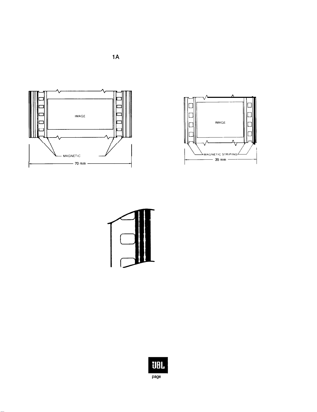
loudspeakers. Options are to use the two remaining magnetic tracks for subwoofer signals and/or split
(dual channel) surrounds.
The 35 mm format was modified during the 1950’s to handle four magnetic tracks: three screen
channels and a single surround channel. At the same time, the standard monophonic variable area
optical track was maintained. Figures IA and B show the channel layout for both 70 mm and 35 mm
magnetic standards. At present, the 35 mm magnetic standard is no longer in general use.
A. 70
mm
0.35
mm
A
I
’
MAGNETiC
STRIPING
Figure 1. 70mm six-track magnetic format (A); 35mm four-track magnetic format (B)
Figure 2A. 35mm Dolby Stereo Optical format
page
3
Page 5
I
rOUTPUTS
--QL
-_o
C
--_o R
-_o
SURROUNDS
0
SUBWOOFER
I
LT
RTO
INPUTS ----
0
ADAPTIVE
MATRIX
*
+
c
MASTER
LEVEL
CONTROL
I
AUDIO
DELAY
-
i kHz
LOW-PASS
FILTER
-
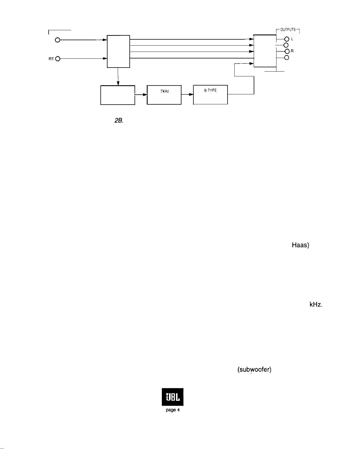
Figure 28. Block diagram of the Dolby Stereo Optical playback matrix
B~TYPE
NR
DECODER
Today, the Dolby Stereo Optical system is virtually a standard format on non-digital 35 mm
film. In this process, the dual bilateral variable area optical sound tracks, which were formerly
modulated with a monophonic signal, are now modulated in stereo, as shown in Figure 2A. Recording
on the two sound tracks is accomplished through a matrix, which accepts inputs for the three screen
channels and the single surround channel. The signals intended primarily for the left and right screen
loudspeakers are fed to the left and right channels. Program material intended for the center screen
loudspeaker, including most on-screen dialog, is fed to both stereo channels in phase. The in-phase
relationship between the stereo channels triggers the playback matrix to steer that information
primarily to the center screen loudspeaker, through a combination of gain control and altering of
separation coefficients within the matrix. In a similar manner, information intended for the surround
channels is fed to both stereo channels so that there is a 180” phase relationship between them. This
phase relationship triggers the playback matrix to steer that information primarily to the surround
loudspeaker array.
Figure 2B shows details of the playback matrix used in Dolby Stereo Optical soundtracks. The
surround channel is delayed relative to the other channels so that, by the precedence (or
Haas)
effect,
the surround channel will not dominate the perceived sound field in the middle and back of the house.
The reason for this is that the matrix output contains certain “leakage” signals that may be disturbing to
a listener if such signals were to be heard from the surround loudspeakers. in practice, the surround
channel is delayed with respect to the screen channels so that the most distant listener in the cinema
will hear that channel delayed by a minimum of 20 milliseconds. Since the ear will “lock in” on earlier
arrival sounds, localization will be maintained in the direction of the screen for all patrons, while effects
intended only for the surround channel will be
problem is further addressed by rolling off the response of the surround channel above about 7
clearly heard from the surround loudspeakers. This
kHz.
B. Digital Film Formats
The Dolby SR-D format, introduced in 1992, is shown in Figure 3A. It has exactly the same
optical sound tracks as shown in Figure 2A with the addition of digital information located in the
otherwise unused space between sprocket holes. This new digital format provides the usual three
screen channels plus a split surround pair and a single low frequency (subwoofer) channel limited to
Page 6
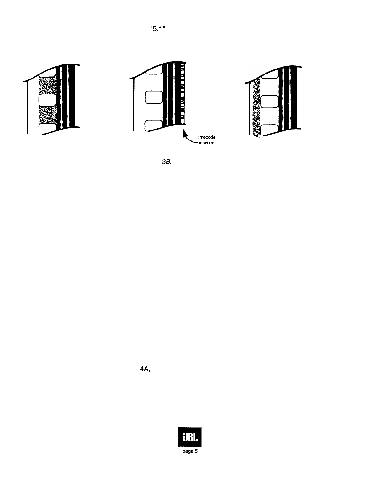
100 Hz. This is commonly referred to as a “5.1’ channel system and uses an elaborate perceptual
encoding process known as AC-3.
timecode
btween
Figure 3A. Dolby SR-D Figure 38. DTS Figure 3C. SDDS
data
optical
tracks and picture
Figure 3B shows the format used in DTS. Here we see only the stereo optical tracks and a
sync channel for maintaining control of the associated CD ROM player.
Figure 3C shows the format used with SDDS. In addition to the stereo optical tracks, there are
two digital tracks, one at each edge of the film.
Like Dolby SR-D, DTS and SDDS make use of perceptual encoding methods for reducing the
amount of digital data required for system operation. DTS and SDDS support the 5.1 channel format
used in most cinemas, but SDDS also supports as many as 5 screen channels for special
applications.
All digital formats discussed here have a fall-back (failsafe) mode in which the analog tracks
will be used in case of failure of the digital portion of the systems.
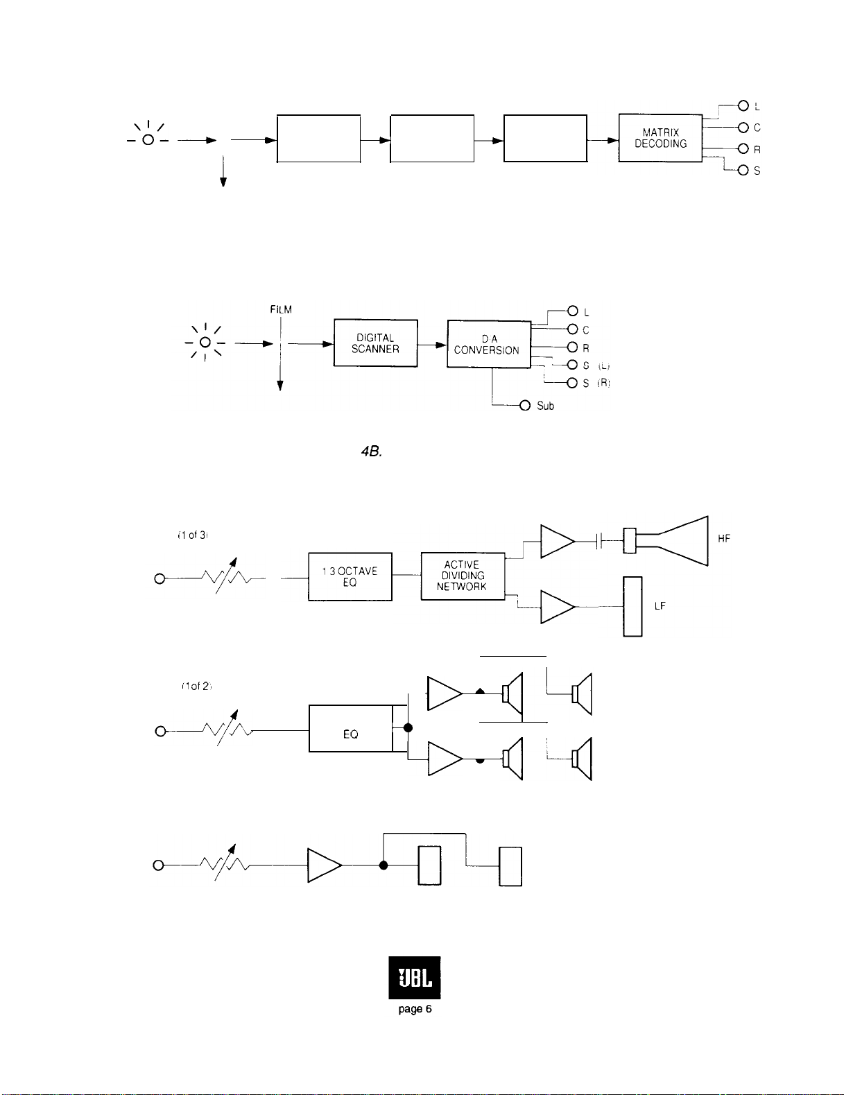
C. A- and B-chains
For convenience in defining responsibilities for system specification and alignment, the
playback chain is customarily broken down into the A-chain and the B-chain, as shown in Figure 4.
The A-chain is comprised of the preamplifiers (optical or magnetic), light source (optical), magnetic
heads, solar cells (optical), associated equalization (signal de-emphasis), and noise reduction and
directional decoding required for flat electrical output at the end of that chain. For digital reproduction,
a digital optical reader is used and the digital signal is fed to a digital-to-analog conversion system.
The analog A-chain is shown in Figure
4A,
and the digital A-chain is shown at B. The B-chain,
including split surround channels, is shown at C.
Page 7
FILM
SIGNAL OUT
--$-I_
___)
‘I’
LAMP
SCREEN CHANNEL
I1
of31
SOLAR
I
h
i
CELL
Figure 4A.
--)
PREAMP
--)
Block diagram of analog A-chain
NOISE
REDUCTION
SIGNAL OUT
-
Figure 48. Block diagram of digital A-chain
MASTER
FADER
SURROUND CHANNEL
il Of
2)
SUB CHANNEL
,:,pg
A
1 3 OCTAVE
EO
_,,
Figure 4C. Block diagram of B-chain with split surrounds
Page 8
The B-chain is comprised of one-third octave equalization, dividing networks (low- or high-level),
power amplification, and loudspeakers. JBL Professional products are used extensively used in the
chain of the system.
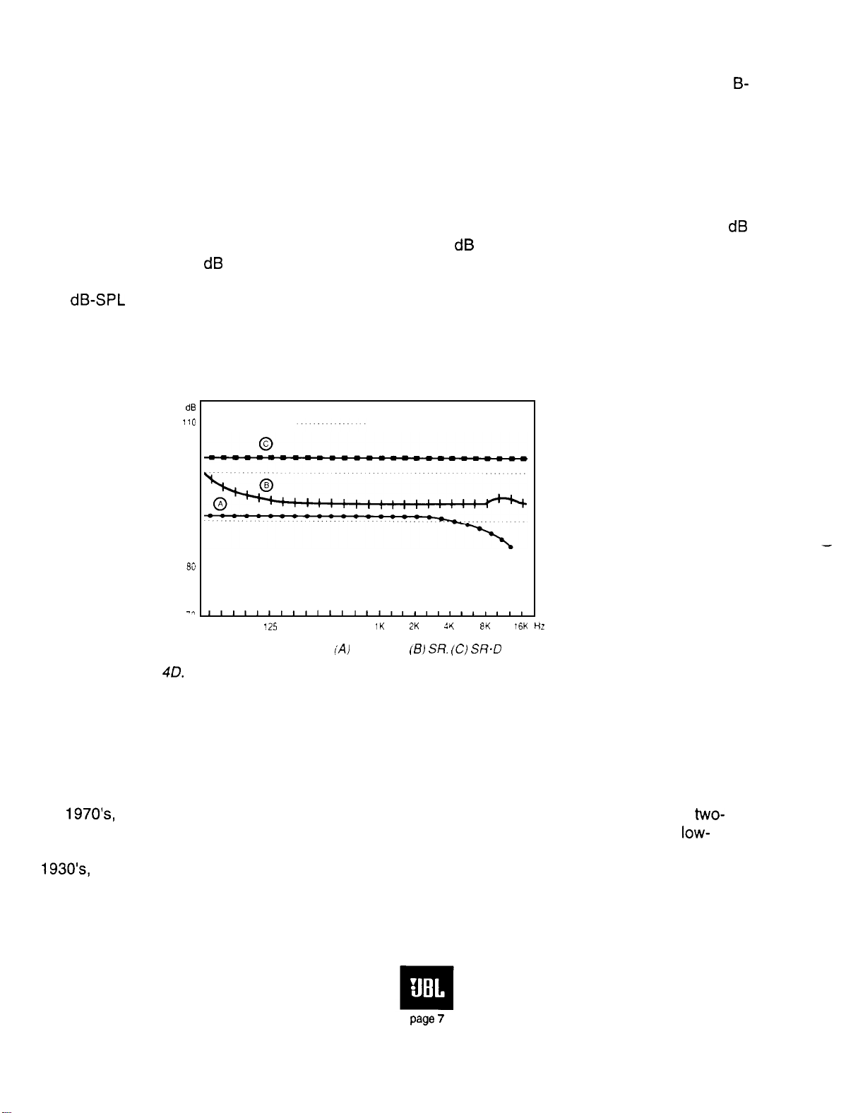
D. Evolving Dynamic Range Requirements in the Cinema
Figure 4D shows details of the headroom requirements of current and future cinema formats.
According to Dolby Laboratories, the level of dialog in the cinema will remain as it currently is, while
the added headroom will be used primarily for more realistic peak levels for sound effects and music.
Depending on specific signal content, the peak level capability of Dolby SR analog tracks can be 3
greater in the mid-band than with Dolby A, rising to about 9 dB at the frequency extremes. The digital
formats can provide 12 dB headroom relative to Dolby A, with overall characteristics that are flat over
the frequency band. This peak capability translates into acoustical levels, on a per-channel basis, of
103 dB-SPL in the house. All of the loudspeaker systems discussed in this manual will meet these
new specifications, consistent with the size of the cinema for which the systems will be specified.
dE
110
100
B-
dB
SO
80
-1
16K
tiz
Figure 40.
1K
2K
:r(
375
63
125
253 500
Peak power levels
(Al
A-type.
(8) SF?. (CI SR.D
8K
Dynamic range requirements for Dolby-A, Dolby SR and Dolby SR-D formats
E. Integration of Loudspeakers into the Acoustical Environment
In order to present a clear picture of the interaction of loudspeakers and the acoustical
environment, we will begin with the previous era in cinema loudspeaker design. Through the end of
the
1970’s,
way designs composed of multicellular or radial high-frequency horns and hybrid horn/reflex
the loudspeaker systems which were current in the cinema were the tried and true
two-
low-
frequency systems. These systems had been developed by Bell Laboratories as far back as the
1930’s,
and the versions used until just a few years ago were essentially the same as has been
developed and refined by Lansing and Hilliard (1). These systems were well engineered in terms of
efficiency, ruggedness, and low distortion, given the acoustical performance demands of the day.
Their designers had also successfully coped with the problems of frequency division and arrival time
page
7
Page 9
differences between high and low frequency sections. The chief weakness of these systems was their
lack of uniform coverage. System design stressed output conversion efficiency, because of the small
power amplifiers available at the time.
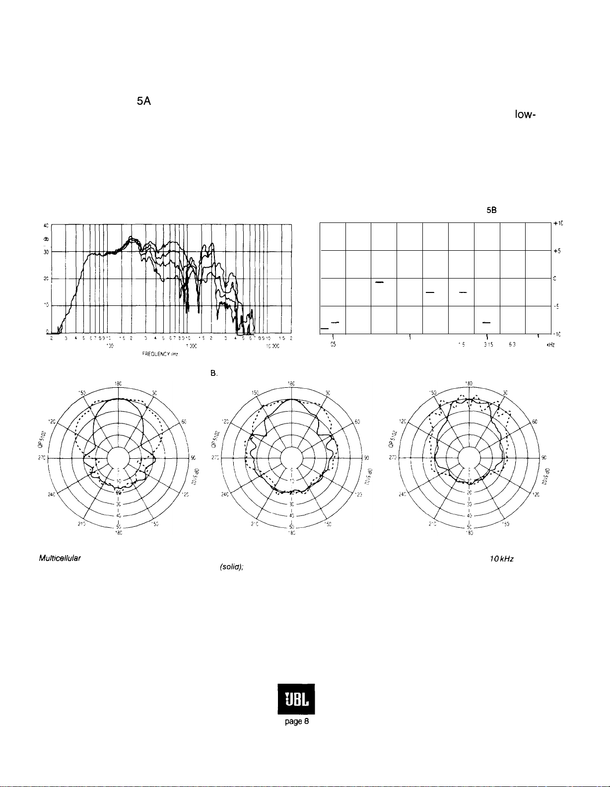
Figure 5A shows the on- and off-axis curves of a typical horn/reflex system, while polar
response of a typical multicellular horn is shown at B. Note that the off-axis response of the
low-
frequency system falls off considerably at higher frequencies. The typical reverberant room response
of a system composed of these elements is shown at C. Note here the double hump, which indicates
that the total power output of the system is far from uniform. At the same time, however, the on-axis
response of the system may be fairly flat, when measured under non-reflective conditions.
A. Off-axis response of ported horn system
C. Reverberant (power) response of a cinema system composed of
elements similar to those shown in Figures 5A and 58
-
-
I
I
c5
8.
Polar characteristics of a 2 x 5 multicellular horn
( -Ii:
'25
.Hi
+1c
+5
c
-5
I
-
-
I-
--
-
I
4
-
-
-
I
I
'5
3
I
3'5 63
I
Mulhcellular horn (2 x 5) 1000 Hz vertical Multicellular horn (2 x 5) 2000 Hz vertical
(soliu);
(so/id); horizontal (dashed)
Figure 5.
horizontal (dashed)
Theatre equalization of old-style cinema system
Multicellular horn (2 x 5) 10
(solid); horizontal (dashed)
If any attempt is made to equalize the response of this system in the cinema, then the response along
the major axis of the system will be anything but flat. This is precisely the problem which Dolby
Laboratories encountered when they introduced equalization into cinemas during the 1970’s.
Page 8
kHz
vertical
Page 10
F. Power Response and Power-Flat Systems
The discrepancy between on-axis and reverberant room response in the older systems was
solved with the introduction of a new family of systems based on uniform coverage high-frequency
horns and simple ported low-frequency enclosures. Figure 6A shows the horizontal off-axis response
of the JBL 4648A low-frequency system. Note that the response is uniform below 500 Hz over a wide
angle. At 6B we show the vertical off-axis response of the 4648A system. Note that the response
begins to narrow just below 200 Hz. The net result of this pattern narrowing in the horizontal and
vertical planes is that they make a good match for the pattern control of the JBL 2360A horn at the
normal crossover frequency of 500 Hz.
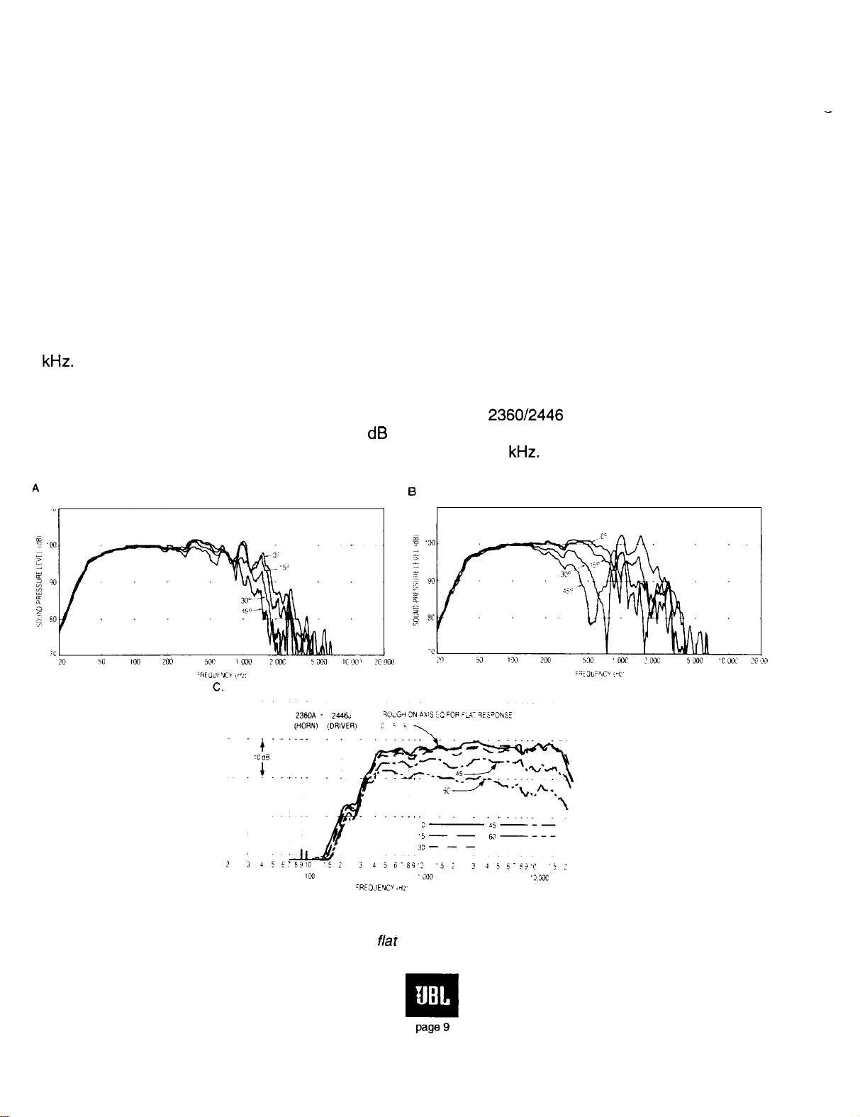
Figure 6C shows the off-axis response curves for the 2360A Bi-Radial horn, coupled to a JBL
2446J high-frequency driver which has been equalized for flat power response. Note that the off-axis
curves are essentially parallel, indicating that the horn produces a solid radiation angle which is
uniform with respect to frequency. The need for equalization of the compression driver comes as a
result of the natural high frequency roll-off which occurs in high frequency drivers above about 3.5
kHz.
This frequency is known as the “mass break point” and is a function of diaphragm mass and
various electrical and magnetic constants in the design of the driver.
When the 4648A or 4638 low-frequency system and the 2360/2446 combination are integrated
into a full range system for cinema use, the -6 dB beamwidth above 500 Hz is smoothly maintained at
90” in the horizontal plane and 40” in the vertical plane out to 12.5
kHz.
At lower frequencies, the
system’s coverage broadens, eventually becoming omnidirectional in the range below 100 Hz.
A
I3
-
Figure 6.
1
(A) Horizontal response; (B) Vertical response; (C) Off-axis response of a JBL 236OA horn
equalized for
flar
power response
Page 11
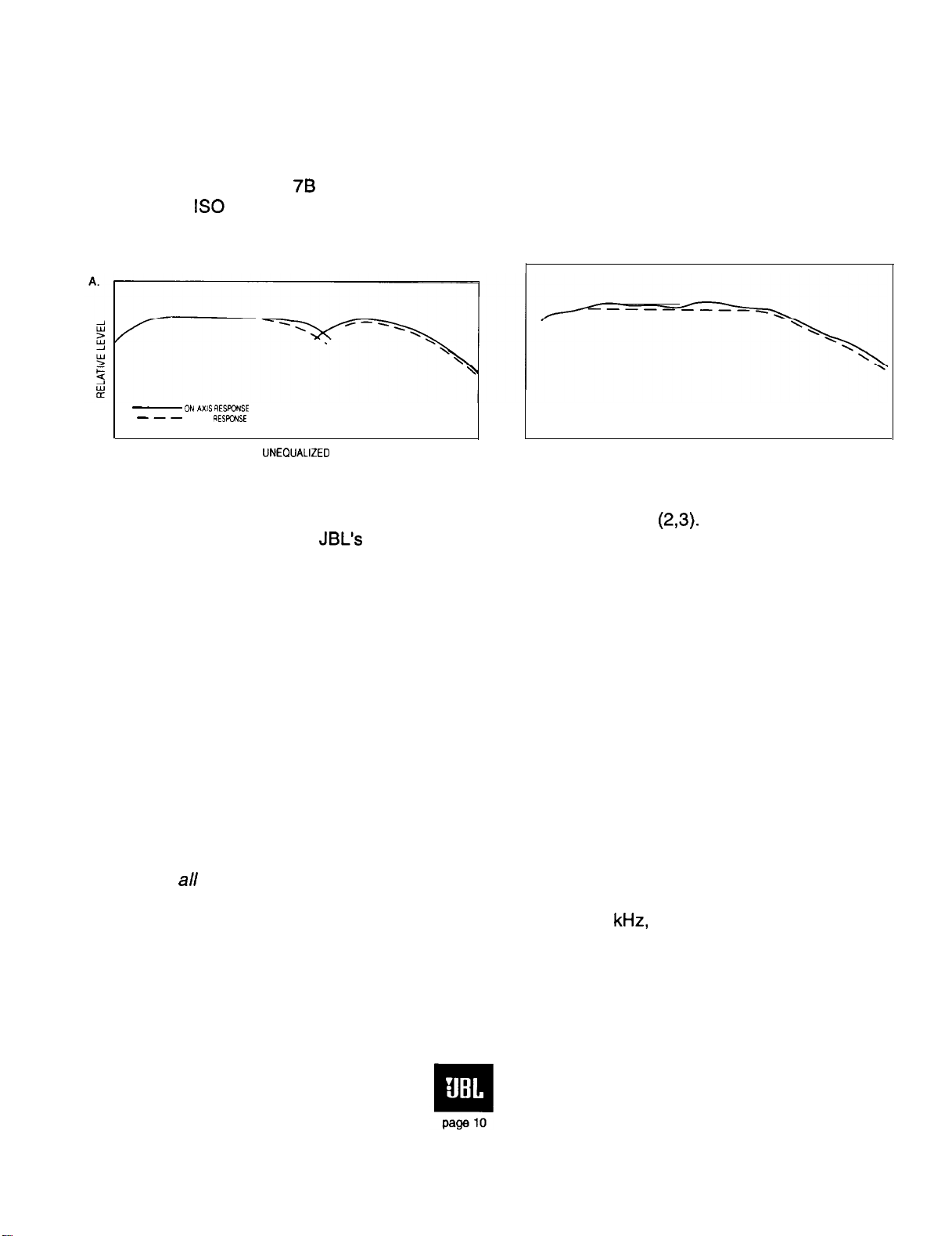
When the system described above is equalized in a typical cinema environment, both direct
sound and reverberant sound can be maintained quite smoothly, as shown in Figure 7A. The system’s
reverberant response is proportional to its power output, or to its power response, and the matching of
the system’s on-axis and power response indicate that the reflected sound field in the cinema will
have the same spectral characteristics as the direct sound from the loudspeaker. When this condition
exists, sound reproduction, especially dialog, will sound extremely natural. (The frequency response
contour shown in Figure 78 is the so-called “X-curve” recommended for cinema equalization, as
specified in
IS0
Document 2969.)
-
ON
*xis
---
POWER
RESPONSE
RESWNSE
UNEOUALIZED
Figure 7.
Cinema equalization of power flat systems
JBL pioneered the concept of flat power response in the cinema
EQUALIZED
(2,3).
It has become the
guiding principle in much of JBL’s product design, and it has been adopted by the industry at large.
G. Coverage Requirements for Proper Stereo Reproduction
In the cinema, it is expected that all patrons will be able to appreciate convincing stereo
reproduction. By contrast, standard two-channel stereo in the home environment often imposes strict
limitations on where the listener must sit in order to perceive correct stereo imaging. The factor that
makes the big difference in the cinema is the presence of the center channel. Not only does the
center loudspeaker lock dialog into the center of the screen, it further reduces the amount of common
mode information the left and right channels must carry, thus making it possible for listeners far from
the axis of symmetry to hear the three channels with no ambiguity or tendency for the signal to
“collapse” toward the nearer loudspeaker. In the Dolby stereo matrix, the same convincing effect is
largely maintained through gain coefficient manipulation during playback.
Ideally, each patron in the house should be within the nominal horizontal and vertical coverage
angles of
all
the high-frequency horns. This requirement can usually be met by using horns with a
nominal 90” horizontal dispersion and by toeing in the left and right screen loudspeakers. In very wide
houses, the spreading of high frequencies above approximately 5
kHz,
as they pass through the
screen at high off-axis angles, actually helps in providing the desired coverage.
Another desirable condition is maintaining levels as uniformly as possible throughout the
house. We have found that aiming the screen systems, both high- and low-frequency, toward the back
wall helps in this regard, by offsetting normal inverse square losses with the on-axis “gain” of the
Page 12
screen systems. Measurements made at the Goldwyn Theater of the Academy of Motion Picture Arts
and Sciences in Beverly Hills, California, show that, over most of the frequency range, front-to-back
levels in the house are maintained within a range of 5
elements toward the audience would produce front-to-back level variations of up to 10 to 12
dB.
By contrast, aiming the high-frequency
dB.
An
important requirement here is that the back wall of the cinema be as absorptive as possible. If the rear
wall is not highly absorptive, then tilt the high frequency loudspeakers down, with the horn’s axis
pointing at the seating area two-thirds of the way back in the house.
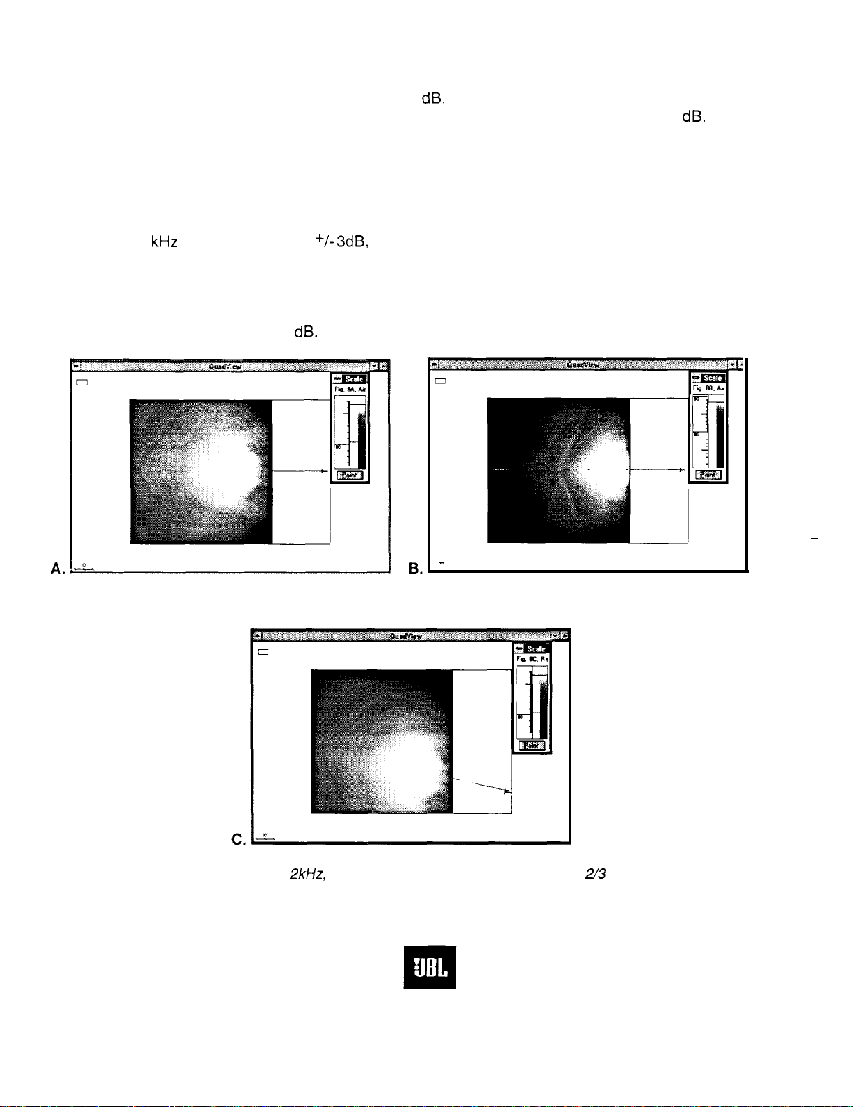
This performance is seen in Figure 8. At A, we show in plan view the direct field coverage
given by a JBL 2360 horn aimed at the absorptive back wall of a large theater with sloped floor.
Coverage at 2
kHz
is within a range of
+/- 3dB,
front to back. If the horn is aimed downward to a point
two-thirds the distance from front to back, the coverage is as shown at B, and coverage at the rear of
the house is compromised. The coverage given by one of the outside horns, aimed at the rear wall, is
shown at C. It is customary to toe in the left and right systems toward the center, whether or not the
screen itself is curved, and the aim is to provide adequate coverage for all patrons, with response
maintained within a total range of 6
dB.
Figure 8.(A) Direct field coverage at
n
2kHz,
aimed at rear wall; (B) Same, horn aimed 2/3 distance front to back;
(C) Coverage of single outside horn.
-
page
11
Page 13
The surround ensemble of loudspeakers, if properly specified, can easily produce a sound
field that is uniform throughout the back two-thirds of the house, and level variations can often be held
within a range of 2 to 3
dB.
Details of surround system specification will be covered in a later section.
L
When all of the above points are properly addressed, the sound in a cinema can approach that
which we take for granted in a post-production screening facility
director intended it to sound. It is only when such details as these have been carefully worked out that
the effects intended by the sound mixer can be appreciated by the viewing audience.
-
which is, after all, how the picture
.-.
III. ACOUSTlCAL
CONSIDERATIONS
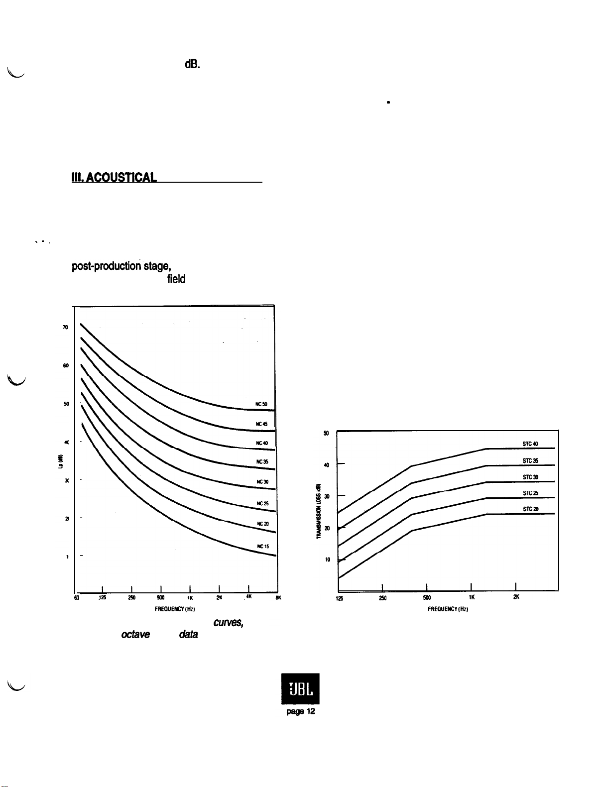
A. Noise Criterion (NC) Requirements
The usual sources of noise in a cinema, outside of the patrons themselves, are air handling
and transmission of noise from the outside. In the case of multiplex installations, there can be leakage
from adjacent cinemas as well. Not much can be done about a noisy audience, but it is true that at the
post-production.stage,
encountered in the
mixing engineers take into account certain masking noise levels which may be
field
and even do the final mix under simulated noisy conditions (4).
63
125
2%
94
FREOUEW
Figure 9. Noise Criterion (NC)
octave
band
IK
(Hz)
data
2ll
wrves,
.(*
xa
FREOUENCV
1K
(Hz)
4K
Figure 10. Sound Transmission Curves
Page 14

Acoustical engineers make use of what are called Noise Criterion (NC) curves in attempting
to.
set a noise performance goal for cinemas. The octave band values of these curves are shown in
Figure 9. In implementing this data, the acoustical designer settles on a given criterion and then
determines the cost and other factors involved in realizing it. Low-noise air handling requires large
ductwork and is expensive. Even more likely to be a problem is through-the-wall isolation from
adjacent cinemas. The general recommendation made by Lucasfilm Limited (5) is that interference
from adjacent cinemas should be audible no more than 1% of the time. Considering that NC-30 may
represent a typical air conditioning noise level for a cinema, the desired degree of isolation between
adjacent spaces does not represent a hardship in terms of wall construction. The need for improving
NC standards in cinemas is a natural consequence of better recording technology and is the only way
that the benefits of Dolby SR and digital formats can be fully appreciated.
As an example of what may be required, let us assume that the normal maximum levels in a
multiplex cinema are 95
that the isolation from an adjacent cinema must be on the order of 65
met, and this will call for a wall structure that will satisfy a Sound Transmission Class (STC) of 65
There are a number of double wall, or single concrete
dB-SPL,
with levels exceeding this value only about 1% of the time. It is clear
dB
if the NC-30 criterion is to be
block
wall, constructions that will satisfy this
dB.
requirement, and economic considerations usually take over at this point. Acoustical engineers and
consultants are usually on firm scientific ground in these matters. Typical standard STC curves are
shown in Figure 10
.
The isolation task is certainly easier with new construction, since buffer areas can be designed
between adjacent exhibition spaces. The most difficult problems occur when older spaces are to be
subdivided to make multiplex cinemas, inasmuch as the chances of coupling through walls or through
common air handling are compounded.
It is obvious that the architect must work closely with an acoustical engineer if the job of
isolating adjacent spaces is to be done correctly. All of this yields to straightforward analysis, but the
job is often a tedious one.
B. Control of Reverberation and Discrete Reflections
After the problems of sound isolation have been addressed, the acoustical engineer then turns
to those problems that are generated entirely
The acoustical ‘signature’ of a cinema
should.be
apparent in most houses, and any perceived
within
the cinema itself; i.e., reverberation and echoes.
neutral. Reverberation per se is not generally
sensa
of reverberation or ambience during film exhibition
normally comes as a result of surround channel program.
This is not to say that the cinema environment should be absolutely reflection-free. Strong
initial reflections from the sides of the house may be beneficial in a concert hall, where they are
needed to produce a sense of natural acoustical space; however, in the cinema, pronounced initial
reflections from any direction should be eliminated.
Traditionally, reverberation time in auditoriums increases at low frequencies and decreases at
high frequencies. This is a natural consequence of the fact that many surfaces that are absorptive at
middle and high frequencies are not very effective sound absorbers at low frequencies. At higher
frequencies, there is additional absorption due to the air itself, and this excess attenuation of high
Page 15

frequencies tends to lower the reverberation time. Figure 11 shows the normal range of reverberation
time, as a function of the value at 500 Hz, while Figure 12 shows the acceptable range of
reverberation at 500 Hz as a function of room volume.
.-.
tm
no
500
FREWEKVIHz)
l.om
zaa
5.m
1O.OLl-J
0.1
Glikl
3
3
&icf*
2760 m’
mMw
ni
Figurn 11.
Variation of
with frequency
reverBem
tion time
Figure
12. Suggested
Em
of revetiration
The requirements of specifying the right finishing materials, along with any special needs for
added low-frequency absorption, fall squarely in the hands of the acoustical designer. In smaller
houses, there is often
little
choice but to make the space acoustically ‘dead;’ however, some degree
of reflectivity, even though it may not be perceived as such, will be beneficial.
Discrete reflections are likely to be a problem only if they clearly are displaced from the direct
sound in both time and spatial orientation. Side wall reflections are usually perceived by the listener
well within a time interval which does not allow them to be heard-as such. However, a reflection off the
back wall can rebound from the screen itself, creating a ‘round trip’ echo that may be delayed by as
much as
100
milliseconds. The effect here is to render dialog difficult to understand. In older cinemas
with balconies, such reflections were often generated by the balcony front (or fascia) itself. Substantial
acoustical damping had to be placed on that surface in order to diminish the problem.
In most cinemas constructed today, echo problems can generally be dealt with by ensuring
that the back wall is very absorptive and that substantial damping is installed behind the screen on the
baffle adjacent to the loudspeakers.
Page 16

C. The Role of the Acoustical Consultant
An acoustical consultant should be chosen on the basis of previous jobs well done. There is
much that is learned simply by having encountered - and solved - many problems. Stating it another
way, an experienced consultant has probably seen most of the common mistakes and knows how to
spot them before they become problems. While much of what a consultant does may seem obvious,
and even simple, it is the breadth of experience that qualifies a good consultant to take on a difficult
task and succeed at it.
In addition to the points discussed so far in this section, the consultant will look for potential
difficulties in the following areas:
1. Flankina leakage
Daths.
When acoustical isolation has been addressed in wall construction,
flanking paths through, or around, the wall may become significant. For example, sound often leaks
through electrical or air conditioning conduit, even though the wall itself may act as a good barrier to
sou,nd
transmission. Such paths can crop up in many places and need to be identified early in the
construction phase of the project.
2. lntearitv in construction. Many building contractors routinely take shortcuts, and somebody needs to
watch them carefully. The acoustical isolation of double wall construction can be nullified by the
presence of material left between them bridging the air barrier between the two sections.
3. lmoact and structure-borne noise. These are some of the most difficult problems to fix, since they
are literally ‘built in.’ Plumbing noises, elevator motors, and air handling machinery located on the roof
are just a few of the offenders here. Once the installation has been made, the problem is very
expensive to correct, and a good consultant will have an eye out for such things at the design stage of
the project. Related problems, such as projector noise and other noises associated with concession
activities need to be identified early in the project and corrected before construction begins.
d,
,
1
As standards for film exhibition continue to improve, such points as we have raised here will
become more important. In a 1992 monograph
(5),
loan Allen of Dolby Laboratories stressed the need
for noise ratings in the cinema lower than NC-25, with NC-30 representing the worst acceptable case.
IV. SPECIFYING THE CORRECT LOUDSPEAKERS AND AMPLIFIERS
A. Hardware Class vs. Room Size
In all but the smallest cinemas, dual low-frequency systems, such as the JBL 4670D and the
4675C,
center, and right positions. The 4670D has the Flat-Front
should be specified. Normally, there will be three of the systems behind the screen in left,
Bi-Radial236OA
horn, while the
467%
has
the large 2360A Bi-Radial horn. The differences in performance are basically high-frequency vertical
pattern control in the range from 500 to 1000 Hz. Whenever possible, the 4675C systems should be
specified, but there are situations where space behind the screen is limited, and the smaller horn must
be used.
Page 17

Both systems are capable of the same acoustical output, inasmuch as they are both limited by
the power handling capabilities of their identical low-frequency sections. Table 1 indicates the
sustained maximum sound pressure level in the reverberant field which these systems can produce,
based on room volume. Levels for a single unit, as well as for the three units, are given. Median
reverberation times as given in Figure 11 are assumed in these calculations, as are system directivity
index and estimated room surface area.
27omp
(10,ooo al. L)
540m3
(20,ooo cu.
13SOm3
(!5o,ooo cu.
2700m3
(100,ooo
5400m3
(200,ooo
ft.)
ft.)
cu. R)
-
104
al. ft.)
Table
JBL
467OD
of various sizes
++7zT
113
108
108
1A:
Maximum
and
118 150
113
111
109
Reverbwant Levels1
467%
Systems in Cinsmas
(non-b&m
plifiedmode)
300
500
loo0
Taking the information presented in Table lA, we can now determine the actual power
requirements to produce target levels in the house of 105
dB
per channel:
800W
800W
800W
800W
for
lReverberant
about
levels, as calculated in
two-thirds from the front
g$!f
(10,ooo cu.
540m3
(20,aoo al.
13SOm3
(!yJ.ooo
al. ft.)
of the house to the back.
7510100
ft.)
150
It.)
300
Tabls
1 B: Power Requirements for
Targst Revebmnt Levels’
in Smaller Houses
Tables 1
A,
6, and C, represents the maximum level that would exist at a point
1oow
25ow
400W
(nowbiam~lifisd
JBLMPX3oo(onechamel)
JBL
JBL
of 105
=
MPX800
MPX800
dB
mode)
(one
(one
chamd)
chard)
Page 18

For spaces of 2700
biampiified mode.
m3
or greater,
JBL recommends that the model 4675C be specified in
d
tt%z
HF:25OW
LF:4oow
HF:2!5OW
(biimpliied
mode).
. _
Table
2700m3
(100,ooo
cu. ft.)
S400m3
(200,ooo
cu. ft.)
1C.
Maximum Reverberant
103dB 113dB
106
Levels’
for JBL
111
4675C
500
loo0
Systems in Large Cinemas
B. Advantages of Biamplification
The importance of biampiification in large cinemas cannot be overestimated. Even though the
systems detailed in Table 1 B use the same amplifier model as the systems detailed in Table
1
A,
the
reallocation of the power through biampiification has important beneficial effects. Specifically,
intermodulation distortion is reduced at-high operating levels, and available power can be more
directly matched to the
specific
HF or LF
load.
C. Cinema Playback Level Calibration
The actual level requirements in the film
makel’s
dubbing cinema are established by relating
them directly with modulation level on the recorded medium. For magnetic media, this is established
as 85
dB-SPL
nanowebers/meter.
ourselves with it further, except to note that modulation peaks often exceed zero level by 8 to 10
Thus, the peak output per loudspeaker may be only 95
additional headroom of 6 to 8 dB above this, so it is clear that the values we have listed in Tables
in the house when the modulation on the tape is so-called ‘zero level,’ or 185
This last quantity has to do with Mording technology, and we need not concern
dB.
Good engineering practice allows
dB.
1A
and B are not excessive in the cases of the larger houses. in the smaller houses, we can certainly
make do with smaller amplifiers than indicated in the table; but even then, the cost of the added power
is very slight, and the benefit substantial. The powers recommended in Tables 1A and B are in
accordance with the suggestions made by Lucasfilm Limited (6) in the specification of THX systems.
2JBL
amplifier
recommended for these applications. The LF loudspeaker section
deliver 400 watts; the HF section presents an S-ohm load, for whii the ampliier can deliver 275 watts.
model MPA400
with appropriate front-end frequency division and power
presents
a
4-ohm
msponse
load, to
equalization, is
which the amplifier
can
:
lm
page
17
Page 19

D. New JBL Driver Developments
Our studies have indicated that, in passive systems, maximum power input to the screen
loudspeakers is essentially network limited. As a result of this, many cinema applications ordinarily will
not require the high power Vented Gap
Coolingm (VGC)
performance designed into the JBL 2226
driver. A more recent model, the 2035, was subsequently designed with a 76 mm (3 in.) voice coil,
retaining the same sensitivity of the 2226. Resulting economies can thus be passed on to the user.
In biamplified systems for larger houses we strongly recommend that the 2226 transducers be
used, because of their higher peak power and transient capabilities.
Figure 13 shows the on-axis response of the dual low frequency 4638 system, which
incorporates two of the 2035 transducers.
E. Mechanical
ml
On-axis response of dual 360 mm
xl
im
200
20
5m
1.000
REQUEW WJ
2.03l
(15
in.) 4636TH LF system.
Details of JBL Screen Loudspeaker Systems
5.m)
ro.om 2o.clm
The main JBL loudspeakers recommended for behind-screen use are discussed in this
section. Since all of these systems are intended for field assembly, we will show them in exploded
views, along with a parts list and a wiring diagram for use with a high-level dividing network.
Figure 14 shows dimensional aspects on field assembled 4670D and
indicating their overall space requirements. The models
4670D-HF,
4671 B, 46736,4675CHF, and
467X
systems, clearly
4638TH are shown, respectively, in Figures 15 through 19.
Passive network hook-up details are shown in Figure 20. Wiring instructions for biamplification
will be discussed in a later section.
Page 20

.-.
FQure
Y
.I-
-
lrn’-
I-
14.
Complete system assembly diagram for 46700 and 46756.
-
17s/r’-
-
-
Page 21

Figure 15
COMPONENT EXPLODED VIEW
Gasket
20810
JBL4670D-HF
Driver,
Hiih F
2446t-t
req
Bracket - Inner
Driver/Horn
$%n
Sale)
Binding
Post
Red. 33750
Blk, 33751
screw
(2)
No.8xV2
FWHD
PH BLK
I
Bracket - Outer
Mounting Base
72109
(Not For Sale)
Assembly
Hardware Kit
72110
(IlkJstrated)
Page 22

:OMPONENT
Port
Tube
57932
(Not For Sale)
EXPLODED VIEW
\
Horn 2370A
6486641
JBL4671B
Network
3llOA
Fwyf$$fz t-bhft3
Instattation
Kit 55343
/
c
Gasket, Vinyl
34499
Use
Mounting Hardwar
IfIchled With
In~tion
Kit 55340
Cabinet 4507
63299
(Not
For
Sele)
J
Page 23

Figure
17
ZOMPONENT EXPLODED
Horn
2380A
64889
Port Tube
57932
(Not For Sale)
VIEW
Driver.
2446J
Diaph Rept
D18R2448
tJMyJ$fif
Installation Kit 57538
support
2508
80851
Use Mounting Hardware
Included With Unit
/
High Freq
Hardware
Network
3115A
47031
lose
Mounting Hardware
Included With
Installation Kit 55343
Gasket,
34499
Vinyt
pg&l
Uee Mounting
Included
Wfih
lnetattation
Kit 55340
Hardware
Cabinet 4507
63299
(Not
For
Sale)
Page 24

Figure 18
COMPONENT
EXPLODED
Gasket
60718-01
VIEW
Bolt (4)
114-20x l-111)
JBL4675GHF
Drhw
Hiih
2446H
Fmq
\
Adapter
60705
Bindin
EzY$Et
Post
Hom236OA
60703-01
Bon
(6)
l/4-20 x
/
\
2-114
/
Washer
Bracket Assy
And Mounting Hardware
72144
25068
Nut
Lockwasher
Washer
Page 25

Figure
19
ZOMPONENT
Port Tube (2)
56144
(Not For Sale)
EXPLODED
Scmw (4)
EE6xW
PHLRGHDhlSSLK\
,g%%;
screw
(6)
56460
No.6x3l4
FLHD PH
ELK
Gasket (2)
34499
Sg$er,
Cone
\
Low Freq (2)
Rep1
Inseri,
Threaded (16)
63154-01
10-32x
l/2
Page 26

Figure 20
FROM
AWLIFIER
+
2mH
LFSPEAKER
FRcA4
AMPLIFIER
-
\
lF
bb
RED EIACK
0
/
f
HF
00
BLACK RED
0
0
0
RED
BLACK
NETWORK FLANGE DN RIGHT SIDE
OF LF ENCLOSURE
46700 wiring diagram
LF
SPWER
FROM
AMPLIFIER
INPUT
-2
Z?
wur
HF DRIVER
+
4671 B wiring diagram
AMPLIFIER
t
-
fk~
0
jED
46738 wiring diagram
NOTE:
Input comctions
as shown
here
provide coned EIA polarity.
4675C wiring diagram
Page 27

F. Subwoofers
‘L
.-.
Subwoofers are an integral part of cinema loudspeaker systems installed in mid- and large-size
houses. In specifying them, the designer must take into account the reduced sensitivity of the ear to
low frequency sounds. Figure 21 shows the Robinson-Dadson equal loudness contours. Note that, for
a reference level of 85 dB at 1
kHz,
frequencies in the range of 30 to 40 Hz will have to be reproduced
15 to 20 dB louder in order to be perceived at the same subjective level.
Figure 21.
FREQUENCY
Robinson-Dadson equal loudness contours.
W Hz
U.
Since low frequencies are essentially nondirectional, we commonly specify subwoofer
hardware by calculating the acoustical power requirements in the cinema for a given sound pressure
level. Assuming that the reverberation times in modern cinemas follow the data presented in Figures
11 and 12, we can present the data shown in the following table:
-P-@Jt
m3
3
Derived from the
tabulated volumes.
revertwant
270m3
(10,ooo w.ft.)
540m3
(20,ooo cu.ft.)
1350m3
(50,ooocu.tt.)
2700
m3
(1ocl.oooal.ft.)
5400m3
(2oo.ooocu.ft.)
Table 2:
level requirements, based on average
Acouetical
Power
10
15
20
40
100
vereue
Cinema Volume
reverberation
times in houses with the
Page 28

When the proper room volume has been determined, the designer then can go to the following
table and pick the required quantity of subwoofer modules that will ensure the needed acoustical
power output:
d
.-.
Number of 2242
1
2
4
8
Table 3: Nominal Efficiency and Acoustical Power Output of
%
4
6 1600 64
12
16
-poww
800
3200
6400 !ioo
A---w
dM
Multiple
16
192
Subwoofer Systems
The designer should choose the next higher increment if the power requirement, based on
room volume, falls between two increments in the above table.
Figure 22 shows an exploded view of the JBL 46458 subwoofer module. Each subwoofer
module should be driven with its own amplifier capable of producing up to 800 continuous watts of
sine wave power into a rated impedance of 8 ohms. A pair of subwoofer modules can be driven by a
single JBL model
606
watts into each of two
MPX1200
amplifier, which is capable of producing continuous sine wave power of
8-ohm
loads.
-
d
4
Actual efficiency of combined units will
vary
depending on the spacing among them.
reasonable estimates.
5 Acoustical
under steady state subwoofer conditions.
output
power has been derated, considering the high-level,
Peak values may be 3 dB
Numbers given here are
longterm
higher,
effects of dynamii compression
depending on nature of program.
Page 29

:OMPONENT
Port
Tube
(Not
For
Sate)
EXPLODED
VIEW
I=/
JBL 4645B
P
Screw
65555
winat
60669-01
\
\
\
Speaker, Low Freq
2242HPL
Page 30

G. Surround Requirements
As a general rule, the total ensemble of surround loudspeakers should be capable of
producing as much acoustical power as a single screen channel. Today, the new JBL 8340 surround
loudspeaker is capable of producing total acoustical power output in the range of about 2 watts. Since
a typical dual woofer JBL screen loudspeaker is capable of producing continuous acoustic power
output of 28 watts, it is clear that 14 of the
8340’s
will be required for power matching. Typically, in a
large house, 12 units will suffice. The careful designer should not go below this quantity.
The enclosure of the 8340 is similar to the older 8330, and the baffle has a downward slope of
15”,
making it possible to mount the rear of the enclosure flush with the walls, while providing smooth
coverage over the seating area. Generally, four of the units are placed on the back wall and four each
on the side walls.
Good surround operation depends on ‘a significant quantity of insignificant sources.’ That is to
say, a patron in the cinema should not be able to identify any one unit, but rather sense the sound
fieldcreated by all of them. While practice may vary, the surround loudspeakers are generally
mounted only in the back two-thirds of the house. The height is often dictated by decor, but they
generally should be at a height of 3 to 4 meters (10 to 13 feet), so that the tilted axis of the 8340 is
pointed at the farthest patrons across the cinema. When this is done, the smoothness of surround
response in the cinema can be maintained within * 2
dB.
Details of surround location are shown in
Figure 23.
A. Plan View
Ill-l
Figure 23.
I
6. Elevation View
C. Section View, as seen from
back of cinema
Plan, elevation, and section views of typical surround installation
Page 31

For digital cinemas with two (“split”) surround channels, we recommend that the minimum
number of loudspeakers per channel be set at 8, making a total of 18 loudspeakers. A series-parallel
hook-up will be useful for each surround channel. Specific power requirements for the surround
channels will be discussed in Section VI-C.
H. Screen Losses
Through-the-screen losses are complex to analyze in detail. The on-axis loss appears to be
a 6
dB/octave rolloff
commencing at about 5
kHz.
However, off-axis response is quite different. At
certain angles, high frequencies are transmitted through the screen with relatively little loss. When an
on-axis HF boost is applied to the signal for proper system response on-axis, patrons seated toward
the sides (off-axis) will hear more HF than those listeners on-axis. This, coupled with the normal
off-
axis fall-off of the horn’s response, tends to maintain a good balance of high and mid frequency
program and enables patrons seated to the sides to enjoy good dialog intelligibility.
.-.
With the newer high frequency hardware, the overall required system equalization is
substantially the requirement for flat system power response. When this is provided, the diffuse field
response measured in the house at a distance one-half to two-thirds back often fits the
IS0
2969 X-
curve rather closely. Details of this are shown in Figure 24.
A.
On-axis
response.
with
and
without
perborated
sawn
Figure 24.
Screen Asses
B.
tBO29BScuM,
and house equalization
From a design viewpoint, the engineer must ensure that there is adequate electrical headroom
in the high frequency drivers to attain flat power response above 3
signal be boosted 6
dB
greater than at mid frequencies. A driver must be specified which can handle this increased input --
dB/octave
above 3
kHz,
and this means that the drive level at 12
kHz.
This usually requires that the
kHz
will be 12
and at the same time be able to provide a good match with the low frequency system. All JBL cinema
systems have been engineered with this requirement in mind.
Page 32

In mid-size screening rooms there is less air loss to deal with, and it is often the case that no
more than a
conservative engineers feel that a
I.
Use of Multiple High Frequency Elements
1
0-dB
boost is required to meet the equalization requirements above 10
lO-dB
boost should never be exceeded.
kHz.
Many
In some very large old-style houses with balconies, a nominal high frequency coverage angle
of 40” is not sufficient to provide vertical coverage. Some systems have been installed with multiple
high-frequency horns to take care of this problem, but the difficulty of interference, or ‘lobing,’ in the
combining of the two horns remains, creating difficulties in system equalization. There are experiments
under way to use stereo synthesizers as a method of alleviating gross effects of interference, but
these experiments are only in the beginning stage (8). For the present, we do not recommend that
horn stacking be applied in the cinema -- unless it is specified by a competent consultant who will take
responsibility for overall system performance.
.-.
V. MOUNTING REQUIREMENTS
A. General Comments
The
following rules generally
1.
They should be located vertically so that the horns are between one-half and two-thirds the
appfy
to screen loudspeakers:
height of the screen.
2.
They should be placed so that the horn flanges are within a distance of 5 to 7 cm (2 to 3 in)
of the screen.
3.
All reflective details, such as logos and polished frames, should be painted matte black so
that they will not show through the screen.
4.
Platforms for loudspeaker mounting should be rigid and completely free from rattles; all
exposed vertical surfaces should be finished with sound absorptive materials.
5.
All other wall areas behind the screen should be finished with sound absorptive materials.
B. Platform and Baffle Construction
If a THX system is specified, all details of the vertical baffle will be taken care of. Where there
is no such specification, the installer will have to construct one large platform, or a number of smaller
ones, depending on costs. Figure 25 shows a detail of a platform for behind-screen use. The
loudspeakers should be mounted on sections of carpet, or some other such material, to inhibit rattles.
Enclosures should be secured with angle brackets so that they have no tendency to move.
Page 33

Frameandbag~,2~4
lumber
-
Bracing mquimd
onhwsium.
1
!mDNTvEw
TOPVIEW
AoED3r4eR&xs(Ar3
-.
. .
I
Figure 25. Isometric view of a
pl$fonn.
Figure 26. wings between screen loudspeakers.
When possible, large wings should be mounted between systems, as shown in Figure 26. The
surfaces should ideally be finished with sound absorptive material,
as.should
any exposed wall areas
behind the screen should be finished with sound absorptive materials.
The screen loudspeakers should be spaced laterally so that good stereo imaging is ensured.
All of the screen loudspeakers should be oriented so that they point to a location on the centerline of
the house at a distance about two-thirds the length of the house. This will require that the left and right
screen loudspeakers be toed in regardless of screen curvature. This will ensure that proper stereo
imaging will be perceived by those patrons seated toward the sides of the house. Taking into account
the requirements for masking for various aspect ratios, the spacing between left and right
loudspeakers should be broad enough to produce ideal stereo for the widest format. Acoustically
transparent masking material should be used so that, when masking is in place, there is negligible
high frequency loss. The wider loudspeaker spacing, when used for a narrower format, will be quite
acceptable, even desirable (5).
C. Subwoofer Mounting
For best results, the subwoofers should be placed on the floor below the screen loudspeakers
and, if possible, against a vertical wall or baffle. They should be clustered together, rest on rubber
pads, and be free of rattles.
Page 34

D .
Surround Mounting
The JBL 2502
systems. The user has a choice of mounting the loudspeakers for horizontal projection or for
mounting bracket will accommodate both the 8330 and the 8340 surround
15”
downward projection.
The electrical response switch on the 8330 and 8340 surrounds should be placed in the IS0
2969 X-curve position for cinema application. Figure 27 shows details of surround mounting, and
Figure 28 shows an exploded view of the 8340.
NOTE: All Hardware
In
installation
Except As Noted
Flat Washer,
.-.
I
3/6
(6)
included
Kii
Figure 27.
Flat Washer.
S/16
(2)
Lock Washer. 5/t6 (2)
I
’
Bolt
From
LoudSpMkeC
Cabinet
2502 Wall Mount bracket used with
8300
set&s sumlund speakers
Page 35

Figure
28
ZOMPONENT
Screw
(8)
762-61 CM@75
No. 6 x
3I4
FLHD 100” BLK
\
Horn/Driver
127-10000-00
JBL8340
EXPLODED
“IEWO
screw (4)
67375
No. 8 x l-114
FLHD PH BLK
(Not For Sale)
Speaker, Low Freq
124-21000-00
NO. 8
x
1
PNHD PH BLK
T-Nut (8)
z%s
Screw (8)
=6x1
BTHD HEX BLK
Page 36

A. Wiring for Non-biamplified Installations
All wiring diagrams shown thus far in this manual are for non-biamplified, single amplifier
application. Care should be taken that all connections are properly served with tinned wires or spade
lugs, if required. The wire should be chosen on the basis of that gauge that will result in no more than
0.5 dB loss between the amplifier and the loudspeaker. Details of wire loss calculation are given in
Section VI-D.
B. Wiring Diagram for a Biamplified Installation
Figure 29 shows a wiring diagram for one of three screen channels of a biamplified
installation. Here, we have shown a generic electronic dividing network with HF and LF outputs. This
approach is now giving way to stereo amplifiers that include electronic frequency division as an input
feature, such as the IM-12 module that is included in the ‘Open Input Architecture’ options available
for
JBL’s
MPA-series power amplifiers.
FROM
CPU
c
RED +
I ’
-
BL-
*
‘-All wires to
barrier
strips to be sewed with
a.
BLOCKING CAPACITOR VALUES FOR DRIVER PROTECTION
5235
+
HI ,.
*
-
*+
*.
%
LO
spa& lugs
+
I’
s*
*,
-
,____.
+
STEREO
AMPLIFIER
+
-
*
+
-
*
**
II
1’
RED +
BL
RED +
-
B4-
‘16 ohm OPEfWKtN
A!WMED
Figum
29.
Wiring
diagmm
for a bi-amp/i&d system
A complete biamplified installation would require five stereo amplifiers. Three of these would
be used for the screen channels, and one each for the surround and subwoofer channels. A stereo
amplifier dedicated to the surround channel would facilitate reconfiguration of. that channel for stereo
operation (split surrounds).
Figures 30 and 31 show block diagrams for typical three channel passive and biamplified
cinema systems respectively. These examples should serve as guidelines for system specification,
and the exact configuration of the system should be left to a qualified cinema systems engineer.
Page 37

.-.
833oort3Nosurrcundloudspeakecstypicaloftwosets
of
four to
six
loudspeakers
Figure 30. Typical passive network cinema system
wired
in
sefieslparallel.
Figwe
3
1.
1
L-
-2
I
8330or8340smnmdlodswkerstypiceloftwosets
of four to six budspeakers wired in
Typical
biamplified
-1
cinemaPr~asw
seri~ralld.
cinema system
-ii!+
lwd2
1
I
Page 38

C. Wiring for Surround Channels
JBL recommends that a stereo amplifier be used for surround power, whether or not split
surrounds will be used. The reason is simply that this will generally result in better
loudspeaker matching as well as facilitating eventual split surround usage.
If there are twelve 4 ohm loudspeakers in the surround array, they can be series-parallel wired
in the booth to give a resulting impedance per side of 6 ohms, as shown in Figure 32A. Twelve 6 ohm
loudspeakers, such as the JBL 6340, can be series-parallel wired to give a resulting impedance per
side of 5.3 ohms. Both wiring arrangements provide equal feed to all loudspeakers.
Amplifiers
+
@-I2
amplifier-
F
Wire nut
00
00
t
Figure
For each 6340,100 to 150 watts should be allocated. Thus, for the 5.3 ohm per side
configuration a single model MPX1200 will be appropriate, with each side feeding a 5.3 ohm load and
delivering approximately 150 watts per loudspeaker.
For the 6 ohm per side configuration, we can specify a single MPA750 amplifier to deliver
about 100 watts per loudspeaker.
In general, determining series-parallel loading of surround loudspeakers is about as
complicated as cinema systems engineering will get in the field. The system designer must carefully
note manufacturer’s specifications regarding amplifier loading. Since most modem transistor amplifiers
carry a 4 ohm rating, the designer needs only to ensure:
1. That the amplifier will not be overdriven in normal operation, and
2. That the individual loudspeakers will receive a signal input within their power rating.
Figure 32A and B detail the series-parallel wiring for both the JBL 6330 and 6340 systems.
328.
Barrier Strip
Wiring at
barn&r
strip in the booth
Page 39

D. Wire Gauges and Line Loss Calculations
Good engineering practice requires that line losses result in no greater than a level loss of 0.5
dB
at the load. In making the calculations to determine the smallest wire gauge that will ensure
adherence to this, the engineer must keep in mind that the loss at the loudspeaker is due to actual
losses in the wiring as well as to losses due to impedance mismatching caused by the added
resistance in the line. The following equation can be used to determine the loss in dB at the
loudspeaker, taking both factors into account:
Loss
(dB)
= 20 log
{Rl/(RL
+
2R1)},
where R1 is the resistance in each of the two wire runs to the load and RL is the nominal load
impedance.
Details of the calculation method are shown in Figure 33. The simplest way to deal with wire
losses is by an iterative design process of selecting a trial gauge of wire, solving for the loss, and then
moving up or down in wire gauge as required to meet the design criterion.
w4TERtum
b-m’)
6.00
6.00
2.50
2.50
1.50
1.50
1.00
1.00
.75
.75
AMERICAN WlRE
IAWG)
GAUGE
RESISTANCE PER
300
METERS
so
NOTE.
Paralleling two identical AWG gauges reduces effective gauge by 3.
‘;K$OO~’
t.0
1.2
1.6
2.0
2.5
3.2
4.0
5.0
6.3
8.0
10.0
SlW.XE
RUN.
OF COPPER
EXAMPLE:
Find
the
power loss at an Ml load due to a 50 meter run of AWG
q+q
R
=
&)x25=
-A-
bo
= a '(2X
PowumbaJ= y-,56,,,
kahIs=10bg,~~,=
somtas
0416fl
x8 = 7zsvdts
4161
a6dn
IL::=7atis
#14
wire.
Figure 33. Wire loss calculations
E. Dividing Network Characteristics
The
primary purpose of a passive dividing network is to feed various parts of the frequency
range into the intended transducers. In addition, practical networks provide for some degree of level
adjustment (usually for the high frequency section only) so that elements of various sensitivities can
be used together. Recent network designs provide additional high frequency power response
equalization, and a very few passive networks provide some degree of time offset (normally in the low
frequency section) to enable specific high and low frequency elements to combine response properly
at the crossover frequency. Active networks accomplish their various operations electronically and are
used in biamplification.
Page 40

The cutoff slope of a network is defined by its order. For each degree of order, the cutoff
rate is 6
16
dB/octave.
dB/octave,
Thus, a third order network will provide transitions in the crossover range of
and a fourth order network will provide transitions of 24
dB/octave.
The most common mistake made in field assembly of non-biamplified JBL cinema loudspeaker
systems is mis-wiring of the dividing network. The data presented in Figure 20 should be studied
carefully, inasmuch all network details are spelled out clearly.
Figure 34A and B shows typical HF and LF response curves for electronic dividing networks
used for cinema applications. The curves shown at A have
12dB/octave
slopes with HF power
response equalization for 2360 series uniform coverage horns. Curves shown at B are for 16
dB/octave
slopes.
3 4 5
3 4 5
12
d6/ocmve.
676910152
with power reqonse correction for
Series horns
A.
2
500 Hz
Figure 34.
F.
System Setup and Checkout
Tfie
vast majority of system performance problems can be avoided through proper design
676910152 3
FFZCUENCVW
Tvpical
r.aa
HF and LF response curves for active frequency dividing networks
4 5
236OA
676910 15
lO.Dx
2
-30
8.500HzlEd~~,withpcmnreeponcleanreQionfor238044
1111111
2 3
4 5 676910
1CQ
1.5
2
3 4tm5
S3ries hams
671910
FRQMlcym
I.066
I1111111
2
3 4 5
I5
676910
lO.CCQ
2
15
procedures and proper assembly. If all has gone well, the system will work, and the field crew can
proceed with final calibration and equalization of the system. Some points seem obvious:
1. When a loudspeaker has been assembled, either in the shop or in the field, it should be
tested with as oscillator-amplifier combination to ensure that there are no buzzes or rattles. Any
defective components should be replaced.
2. As each pair of loudspeaker lines is laid, the ends at the loudspeaker should be shorted and
a resistance check made at the booth. Any discrepancies should be corrected.
3. Set up a gain-loss diagram for the system prior to making any adjustments on the system.
An example is given in Figure 35. Here we have shown the divisions of gains and losses in a screen
channel for a non-biamplified system. Since most cinema systems have the same basic architecture, it
is only necessary to establish the norms once.
Page 41

+16
+10
lmJ
0
t24
+20
+10
t6dBu 0
106d8@lm
c
L
62dBQ2Om~Ims
-10
-20
-30
-40
-50
-60
-70
all
-w
-100
-10
-20
-3
-40
-XI
-60
-70
Setiprtdan@ierso,Ihat
t6dBuinpmducesoutputd
2kdB@lm
-
2dE@2omuas
t6av(&3mlts)inb6dnw
Figure 35.
Tvpical
gain-loss diagram for the B-chain of a cinema system
Note that the gain-loss diagram for this system indicates clearly maximum output levels of each
component in the system as well as the noise floor of each component. The goal in proper systems
engineering is to ensure that the widest possible dynamic range is preserved through the chain. No
electronic device ahead of the power amplifier should be driven into distortion before the power
amplifier itself has reached its maximum output capability. Additionally, the noise floor of the system,
once it has been established at the preamp, should not be compromised by allowing the signal level to
fall too low at any subsequent point in the chain. The gain-loss diagram is a convenient means of
ensuring all these points.
All aspects of A-chain calibration should be performed according to the methods laid down in
the various manuals supplied by the manufacturer’s of the cinema processing equipment.
Page 42

References
J. Lansing and J. Hilliard, ‘An Improved Loudspeaker for Theaters,’ Journal SMPTE, vol. 45, pp.
1.
339-349 (1945).
2.
M. Engebretson and J. Eargle, “Cinema Sound Reproduction Systems: Technical Advances and
System Design Considerations,’ Journal SMPTE, vol. 91, no. 11 (November 1982).
3.
J. Eargle, J. Bonner, and D. Ross, ‘The Academy’s New State-of-the-Art Loudspeaker System,’
Journal SMPTE, vol. 94, no. 8 (June 1985).
4.
SMPTE Engineering Guideline: Acoustical Background Noise Levels in Dubbing Stages, EG
1987.
5.
I.
Allen, ‘Technical Guidelines for Dolby Stereo Theatres,’
T.
Holman, “THX Sound System Instruction Manual; Architect’s and Engineer’s Edition, Lucasfilm
6.
Dolby Laboratories, September 1992.
Limited, 1987.
7.
M.
Gander and J. Eargle, “Measurement and Estimation of Large Loudspeaker Array
Performance,” Journal AES, vol. 38, no. 4 (April 1990).
E. Cohen, et al., ‘Use of Stereo synthesis to Reduce Subjective/Objective Interference Effects:
8.
The Perception of comb filtering, Part
11;”
(Preprint number 2862, presented at the 87th
Convention of the Audio Engineering Society, New York, 18-21 October 1989).
14-
Page 43

JBL Professional
8500 Balboa Boulevard
Northridge,
H
A Harman
California 91329 USA
InternatoM
Company
@Copyright 1998 JBL Professional
Printed in USA
 Loading...