

Page 1

880
1400
15001500
ProjectArrray
P
roject Arrray
Project Arrray
880
800
1400
15001500
P
rojectArrray
Project Arrray
Project Arrray
Project Arrray
800
1000
1400
1
P
roject Arrray
Project Arrray
Project Arrray
880
15001500
ProjectArrray
P
roject Arrray
880
Project Arrray
JBL PROJECT
500 ARRA
1
ARRA
Y
Y, 1400 ARRAY,
®
™
1000 ARRAY, 880 ARRAY,
800 ARRA
Y
OWNER’S GUIDE
Page 2
READ FIRST! Important Safety Precautions!
T
he exclamation point within an equilateral
triangle is intended to alert the user to the
presence of important operating and
maintenance (servicing) instructions in the
l
iterature accompanying the appliance.
CAUTION
R
ISK OF ELECTRIC SHOCK
D
O NOT OPEN
CAUTION: To reduce the risk of electric shock,
d
o not remove cover (or back).
No user-serviceable parts inside.
R
efer servicing to qualified service personnel.
CAUTION: To prevent electric shock,
do not use this (polarized) plug with
an extension cord, receptacle or other outlet
u
nless the blades can be fully inserted to
prevent blade exposure.
The lightning flash with arrowhead symbol,
within an equilateral triangle, is intended to
a
lert the user to the presence of uninsulated
“dangerous voltage” within the product’s
enclosure that may be of sufficient magnitude to constitute
a risk of electric shock to persons.
moving the cart/apparatus
combination to avoid injury from
tip-over.
13. Unplug this apparatus during
lightning storms or when unused for
long periods of time.
14. Refer all servicing to qualified
service personnel. Servicing is
r
equired when the apparatus has
been damaged in any way, such
as power-supply cord or plug is
damaged, liquid has been spilled
or objects have fallen into the
a
pparatus, the apparatus has been
exposed to rain or moisture, does
not operate normally, or has been
dropped.
1. Read these instructions.
2. Keep these instructions.
3. Heed all warnings.
4. Follow all instructions.
5. Do not use this apparatus near
water.
6. Clean only with a dry cloth.
7. Do not block any ventilation
openings. Install in accordance with
the manufacturer’s instructions.
8. Do not install near any heat
sources such as radiators, heat
registers, stoves or other apparatus
(including amplifiers) that produce
heat.
9. Do not defeat the safety purpose
of the polarized or grounding-type
plug. A polarized plug has two
blades with one wider than the
other. A grounding-type plug has
two blades and a third grounding
prong. The wide blade or the third
prong are provided for your safety.
If the provided plug does not fit into
your outlet, consult an electrician
for replacement of the obsolete
outlet.
10. Protect the power cord from
being walked on or pinched,
particularly at plugs, convenience
receptacles and the point where
they exit from the apparatus.
11.
Only use attachments/
accessories specified by the
manufacturer.
12. Use only with the cart, stand,
tripod, bracket or table
specified by the
manufacturer or sold
with the apparatus. When
a cart is used, use caution when
2
15. Do not use attachments not
recommended by the product
manufacturer, as they may cause
hazards.
16. This product should be operated
only from the type of power source
indicated on the marking label. If
you are not sure of the type of
power supply to your home, consult
your product dealer or local power
company. For products intended to
operate from battery power or other
sources, refer to the operating
instructions.
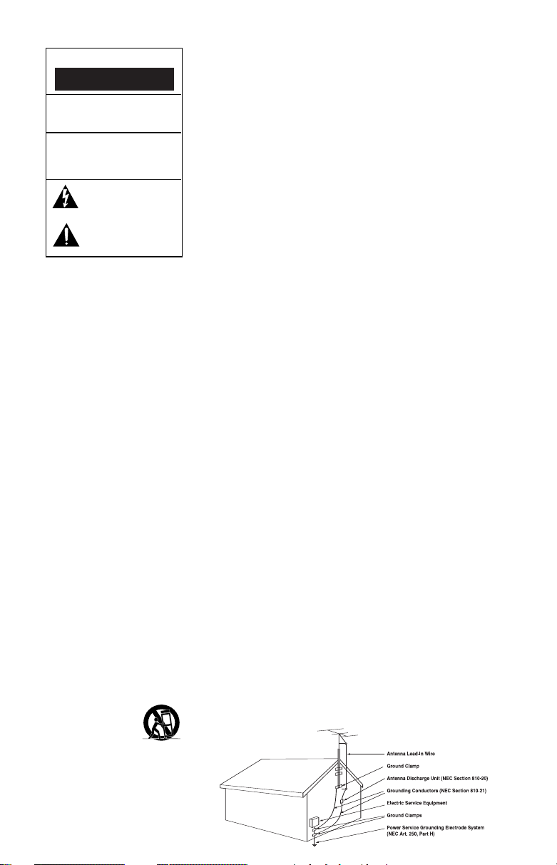
17. If an outside antenna or cable
system is connected to the product,
be sure the antenna or cable
system is grounded so as to provide
some protection against voltage
surges and built-up static charges.
Article 810 of the National
Electrical Code, ANSI/NFPA 70,
provides information with regard to
proper grounding of the mast and
supporting structure, grounding of
the lead-in wire to an antenna
discharge unit, size of grounding
conductors, location of antennadischarge unit, connection to
grounding electrodes, and
requirements for the grounding
electrode. See Figure A.
18. An outside antenna system
should not be located in the vicinity
of overhead power lines or other
electric light or power circuits, or
where it can fall into such power
e A.
Figur
ample of Antenna Grounding as per
Ex
National Electrical Code ANSI/NFPA 70
lines or circuits. When installing an
outside antenna system, extreme
care should be taken to keep from
touching such power lines or circuits,
as contact with them might be fatal.
19. Do not overload wall outlets,
extension cords, or integral
convenience receptacles, as this
c
an result in a risk of fire or
electric shock.
20. Never push objects of any kind
into this product through openings,
as they may touch dangerous
v
oltage points or short-out parts,
which could result in a fire or
electric shock. Never spill liquid
of any kind on the product.
21. The apparatus shall not be
exposed to dripping or splashing,
and no objects filled with liquids,
such as vases, shall be placed on
the apparatus.
22. Do not attempt to service this
product yourself, as opening or
removing covers may expose you to
dangerous voltage or other hazards.
Refer all servicing to qualified
service personnel.
23. When replacement parts are
required, be sure the service technician has used replacement parts
specified by the manufacturer or
that have the same characteristics
as the original part. Unauthorized
substitutions may result in fire,
electric shock or other hazards.
24. Upon completion of any service
or repairs to this product, ask the
service technician to perform safety
checks to determine that the
product is in proper operating
condition.
25. The product should be mounted
to a wall or ceiling only as recommended by the manufacturer.
Page 3
THANK YOU FOR CHOOSING JBL
®
For more than 60 years, JBL
has been involved in every
aspect of music and film
recording and reproduction,
from live performances to the
recordings you play in your
home, car or office.
We’re confident that the
JBL system you have chosen
will provide every note of
enjoyment that you expect –
and that when you think about
purchasing additional audio
equipment for your home, car
or office, you will once again
choose JBL.
Please take a moment to
register your product on our
Web site at www.jbl.com.
It enables us to keep you
PROJECT ARRAY
Project Array loudspeakers
are an extremely high-performance design intended for
uses ranging from premium
two-channel stereo to multichannel home theater
applications. The series is
modular and consists of five
system elements:
1400 Array – floorstanding
1000 Array – floorstanding
800 Array – bookshelf
880 Array – center channel
1500 Array – powered
subwoofer
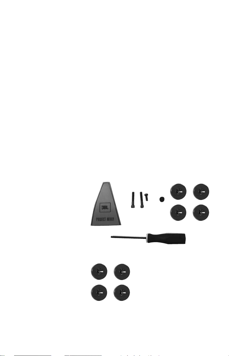
INCLUDED
1400 Array
2 Long 1/4" x 20 Allen-head bolts
1 Short 1/4" x 20 Allen-head bolts
1 Logo plate
1 Allen-head screw driver
1 Rubber hole plug
4 Metal coasters
(to protect floor from spiked feet)
posted on our latest advancements, and helps us to better
understand our customers and
build products that meet their
needs and expectations.
JBL Consumer Products
™
1000 Array, 800 Array and
1500 Array
4 Metal coasters
(to protect floor from spiked feet)
3
Page 4
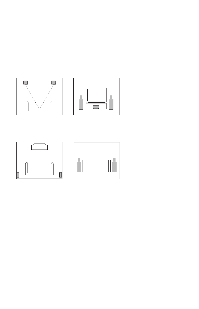
SPEAKER PLACEMENT
IMPORTANT NOTE: The 800,
1000, 1400 and 1500 Array
models feature spiked feet for
optimum acoustic performance.
5.1-CHANNEL SYSTEM
ront Speakers
F
Surround Speakers
However, spikes can damage
certain types of floors, such as
hardwood. In such instances,
place included metal coasters
Center Channel
Speaker
between the spiked feet and
the floor.
The front speakers should be
placed the same distance from
each other as they are from
the listening position, with
tweeters at about the same
height from the floor as the
listeners’ ears will be.
The center channel speaker
should be placed below the
television and no more than
two feet below the tweeters
of the left and right speakers.
The two surround speakers
should be placed slightly
behind the listening position
and, ideally, should face each
. If that is not possible,
other
4
they may be placed on a wall
behind the listening position,
facing forward. The surround
speakers should not call attention to themselves. Experiment
with their placement until you
hear a diffuse, ambient sound
accompanying the main
program material heard in
the front speakers.
The low-frequency material
reproduced by the subwoofer
is mostly omnidirectional, and
this speaker may be placed in
a convenient location in the
room. However, the best
reproduction of bass will be
heard when the subwoofer
is placed in a corner along
the same wall as the front
speakers. Experiment with
subwoofer placement by
temporarily placing the
subwoofer in the listening
position and moving around
the room until the bass reproduction is best. Place the
subwoofer in that location.
Page 5

6.1-CHANNEL SYSTEM
A 6.1-channel system will
consist of a 5.1-channel
configuration, as shown on
page 4, with the addition of a
rear center speaker placed
midway between the two
surround speakers, and
further to the rear than the
7.1-CHANNEL SYSTEM
Some newer surround sound
formats utilize left and right
surround channels that are
used for side fill, in addition
to the left and right rear channels found in 5.1 systems.
Place the left and right
surround speakers on the
surrounds. The rear center
speaker should not call more
attention to itself than the
surround speakers.
sides of the room, at or in
front of the listening position,
facing each other.
5
Page 6

1400 ARRAY ASSEMBLY
Due to the weight of the
1400 Array horn module, it
is packed separately from
the low-frequency enclosure.
It is a very simple procedure
to install the module, and the
necessary instructions are
listed below. The required
Allen-tipped screw driver is
included in the accessory
pack.
1. Carefully remove the horn
module from the packaging
and place it face down on a
soft surface.
2. Locate the cardboard
accessory sleeve and
remove the hardware.
3. The accessory sleeve
should contain:
a. 2 Long 1/4" x 20 Allen-
head bolts
b. 1 Short 1/4" x 20 Allen-
head bolt
c. 1 Logo plate
d. 1 Rubber hole plug
e. 4 Metal coasters
(to protect wood and tile
floors from the spike feet)
4. Carefully unpack the lowfrequency enclosure and
place it upright. It would be
helpful to position it near its
final position in the room
since it is much easier to
move without the additional
weight of the horn module.
5. Notice the two threaded
inserts on the angled face
of the top and also the small
L-bracket on the top. These
are the attachment points
for the horn module. Immediately adjacent to the Lbracket is a recessed connector which will make the
electrical connection for the
horn module.
6. Although the module can
be installed by one person,
it is easier if a second set
of hands are available.
7. Cradle the horn module with
the opening along your forearm and, using your free
hand, connect the plug
coming from the bottom of
the horn assembly into the
jack on the top of the
enclosure.
8. You can now place the horn
in position on top of the
enclosure. The L-bracket
fits in an opening under the
horn assembly. The module
will sit on top of the enclosure by itself, although it
should always be steadied
until fully mounted.
9. Line up the two mounting
holes on the lower lip of the
front of the horn with those
in the enclosure. Partially
install one long bolt and
then the other one. It may
be necessary to lift the horn
slightly so that the bolts
install smoothly. Do not
force or cross-thread them.
10. Once both bolts have been
started, work them in all of
the way, but do not tighten
them securely just yet.
11. Install the remaining short
bolt in the hole at the
bottom rear of the horn
module. You can fully
tighten this bolt.
12. Now completely tighten the
two front bolts.
13. Everything should be tight
and properly aligned at this
time. If not, loosen, realign,
and retighten as required.
14. The final steps are to
remove the backing from
the logo badge and place it
in the recess on the lower
horn lip, and to use the
rubber hole plug to hide the
hole at the bottom rear of
the horn module. Do not
complete these steps until
the system has been turned
on and tested acoustically.
Make sure the horn module
is playing first. Once the
logo badge and rubber
plug hole are installed, it
is extremely difficult to
remove them.
6
Page 7

Step 7
Step 8
Step 9
Step 11
7
Page 8

SPEAKER CONNECTIONS
0
1
2
34
567
8
SUBWOOFER OR
LFE OUTPUT
SUBWOOFER OR
LFE OUTPUT
SSuubbwwooooffeerr CCoonnttrroollss aanndd CCoonnnneeccttiioonnss ((11550000 AArrrraayy OOnnllyy))
¡ Line-Level Input
™ Line-Level Output
£ Power Indicator
¢ Subwoofer Level (Volume) Control
∞ Crossover Adjustment
§ Phase Switch
¶ LP/LFE Selector
• On/Off Auto Switch
ª Power Switch
Connection:
If you have a Dolby®Digital or DTS
®
receiver/processor with a low-frequencyeffects (LFE) output, set LFE/LP switch to
LFE. If you prefer to use the crossover
built into the 1500 Array, set the LFE/LP
¶ to LP.
Switch
The 1500 Array includes
a line output. This output
allows you to “daisy chain”
one 1500 Array to multiple
1500 Array subwoofers.
Simply connect the first
subwoofer as described
above and then run a
subwoofer cable from the
line output(s) to the line
input on the next sub.
8
Page 9

1500 ARRAY OPERATION
Power On
Plug your subwoofer’s AC cord
into a wall outlet. Do not use
the outlets on the back of the
receiver.
Initially set the Subwoofer
Level (Volume) Control
the “min” position.
Turn on your sub by pressing
the Power Switch ª on the
rear panel.
Auto On/Standby
With the Power Switch ª
in the “on” position, the Power
Indicator LED £ will remain
backlit in red or green to
indicate the On/Standby
mode of the subwoofer.
RED = STANDBY (No signal
detected, Amp Off)
GREEN = ON (Signal detected,
Amp On)
The subwoofer will automatically enter the Standby
mode after approximately 10
minutes when no signal is
detected from your system.
The subwoofer will then power
ON instantly when a signal is
detected. During periods of
normal use, the Power Switch
ª can be left on. You may turn
off the Power Switch
extended periods of nonoperation, e.g., when you are
away on vacation.
If the Auto Switch
“on” position, the subwoofer
will remain on.
Adjust Level
Turn on your entire audio
system and start a CD or movie
soundtrack at a moderate
level. Turn up the Subwoofer
Level (Volume) Control ¢
about halfway
emanates from the subwoofer,
check the AC-line cord and
input cables. Are the connectors on the cables making
proper contact? Is the AC
¢ to
ª for
• is in the
. If no sound
plug connected to a “live”
receptacle? Has the Power
ª been pressed to
Switch
the “on” position? Once you
have confirmed that the subwoofer is active, proceed by
playing a CD or movie. Use a
selection that has ample bass
information.
Set the overall volume control
of the preamplifier or stereo
to a
comfortable level. Adjust
the Subwoofer Level (Volume)
Control
¢ until you obtain a
pleasing blend of bass. Bass
response should not overpower the room but rather
should be adjusted so there is
a harmonious blend across the
entire musical range. Many
users have a tendency to set
the subwoofer volume too
loud, adhering to the belief
that a subwoofer is there to
produce lots of bass. This is
not entirely true. A subwoofer
is there to enhance bass,
extending the response of
the entire system so the bass
can be felt as well as heard.
However, overall balance
must be maintained or the
music will not sound natural.
An experienced listener will
set the volume of the subwoofer so its impact on bass
response is always there but
never obtrusive.
Crossover Adjustments
NOTE: This control will have
no effect if the LP/LFE Selector
Switch ¶ is set to “LFE.” If
you have a Dolby Digital or
DTS processor/receiver, the
Crossover Frequency is set
by the processor/receiver
Consult your owner’s manual
to learn how to view or change
this setting.
The Crossover Adjustment
∞ determines the
Control
highest frequency at which the
subwoofer reproduces sounds.
.
If your main speakers can
comfortably reproduce some
low-frequency sounds, set this
control to a lower frequency
setting, between 50Hz and
100Hz. This will concentrate
the subwoofer’s efforts on
the ultradeep bass sounds
required by today’s films and
music. If you are using smaller
bookshelf speakers that do
not extend to the lower bass
frequencies, set the Crossover
Adjustment Control to a higher
setting, between 120Hz and
150Hz.
Phase Control
The Phase Switch § deter-
mines whether the subwoofer
speaker’s pistonlike action
moves in and out with the main
speakers (0˚) or opposite the
main speakers (180˚). Proper
phase adjustment depends
on several variables, such as
subwoofer placement and
listener position. Adjust the
Phase Switch to maximize
bass output at the listening
position.
9
Page 10

GENERAL CONNECTION INFORMATION
Separate and strip the ends of
the speaker wire (not supplied)
as shown. Speakers and
electronics terminals have
corresponding (+) and (–)
terminals. Most manufacturers
of speakers and electronics,
including JBL, use red to
denote the (+) terminal and
black for the (–) terminal.
The (+) lead of the speaker
wire is sometimes noted with
a stripe or other demarcation.
It is important to connect both
speakers identically: (+) on the
speaker to (+) on the amplifier
and (–) on the speaker to (–)
on the amplifier. Wiring “out of
phase” results in thin sound,
weak bass and a poor
stereo image.
With the advent of multichannel surround sound
systems, connecting all of
WIRING THE SYSTEM
IMPORTANT: Make sure all
equipment is turned off before
making any connections.
For speaker connections, use
a high-quality speaker wire
with polarity coding. The side
of the wire with a ridge or other
coding is usually considered
positive (+) polarity.
NOTE: If desired, consult
your local JBL dealer about
speaker wire and connection
options.
The speakers have coded
terminals that accept a variety
of wire connectors. The most
common connection is shown
in Figure 1.
To ensure proper polarity,
connect each + terminal on
the back of the amplifier or
receiver to the respective +
(red) terminal on each speaker,
as shown in Figure 2. Connect
the – (black) terminals in a
similar way. See the owner’
guides that were included
with your amplifier, receiver
and television to confirm
connection procedures.
IMPORTANT: Do not reverse
polarities (i.e., + to –or –to +)
when making connections.
Doing so will cause poor
imaging and diminished bass
response
10
..
Figure 1
Figure 2
FINAL
ADJUSTMENTS
Check the speakers for
playback, first by setting the
system volume control to a
minimum level, and then by
applying power to your audio
system. Play a favorite music
s
or video segment and increase
the system volume control to a
comfortable level.
NOTE: You should hear
balanced audio reproduction
across the entire frequency
spectrum. If not, check all
wiring connections or consult
the authorized JBL dealer from
whom you purchased the
system for more help.
the speakers in your system
with the correct polarity
remains equally important in
order to preserve the proper
ambience and directionality
of the program material.
Both the amount of bass you
hear and the stereo-image
quality will be affected by a
number of different factors,
including the room’s size and
shape, the construction
materials used to build the
room, the listener’s position
relative to the speakers, and
the position of the speakers in
the room.
Listen to a variety of music
selections and note the bass
level. If there is too much bass,
move the speakers away from
nearby walls. Conversely, if you
place the speakers closer to
the walls, there will be more
bass output.
Nearby reflecting surfaces can
adversely affect stereo-imaging
quality. If this happens, try
angling the speakers slightly
inward toward the listening
position until the optimum
effect is achieved.
CARE OF YOUR
SPEAKER SYSTEM
Each Project Array enclosure
has a finish that does not
require any routine maintenance. When needed, use
a soft cloth to remove any
fingerprints or dust from
the enclosure or grille.
NOTE: Do not use any cleaning
products or polishes on the
cabinet or grille.
Page 11

TROUBLESHOOTING
f there is no sound
I
rom any of the
f
speakers:
• Check that receiver/amplifier
is on and a source is playing.
• Check all wires and connections between receiver/
amplifier and speakers. Make
sure all wires are connected.
Make sure none of the speaker
wires are frayed, cut or
punctured.
• Review proper operation of
your receiver/amplifier.
If there is no sound
coming from one
speaker:
• Check the “Balance” control
on your receiver/amplifier.
• Check all wires and connections between receiver/
amplifier and speakers. Make
sure all wires are connected.
Make sure none of the
speaker wires are frayed,
cut or punctured.
• In Dolby Digital or DTS
modes, make sure that the
receiver/processor is configured so that the speaker in
question is enabled.
If there is no sound
from the center
speaker:
• Check all wires and connections between the receiver/
amplifier and speaker. Make
sure all wires are connected.
Make sure none of the
speaker wires are frayed,
cut or punctured.
• If your receiver/processor is
set in Dolby Pro Logic
®
mode,
make sure the center speaker
is not in phantom mode.
• If your receiver/processor
is set in Dolby Digital or DTS
mode, make sure the receiver/
processor is configured so
that the center speaker is
enabled.
f the system plays
I
t low volumes but
a
shuts off as volume
s increased:
i
• Check all wires and connections between receiver/
amplifier and speakers. Make
sure all wires are connected.
Make sure none of the speaker
wires are frayed, cut or
punctured.
• If more than one pair of main
speakers is being used, check
the minimum impedance
requirements of your
receiver/amplifier.
If there is low (or
no) bass output
(1500 Array):
• Make sure the connections
to the left and right “Speaker
Inputs” have the correct
polarity (+ and –).
• Make sure the subwoofer
is plugged into an active electrical outlet.
• Make sure the Power Switch
ª is on.
• In Dolby Digital or DTS
modes, make sure your
receiver/processor is configured so that the subwoofer
and LFE output are enabled.
• Adjust the Subwoofer Level
¢.
Control
If there is no sound
from the surround
speakers:
• Check all wires and con-
nections between receiver/
amplifier and speakers. Make
sure all wires are connected.
Make sure none of the speaker
wires are frayed, cut or
punctured.
• Review proper operation of
your receiver/amplifier and its
surround sound features.
• Make sure the movie or TV
show you are watching is
recorded in a surround sound
mode. If it is not, check to see
whether your receiver/amplifier
has other surround modes you
may use.
• In Dolby Digital or DTS modes,
make sure your receiver/
processor is configured so
that the surround speakers
are enabled.
• Review the operation of your
DVD player and the jacket of
your DVD to make sure that
the DVD features the desired
Dolby Digital or DTS mode,
and that you have properly
selected that mode using both
the DVD player’s menu and the
DVD disc’s menu.
11
Page 12

SPECIFICATIONS
1
400 ARRAY 1000 ARRAY 800 ARRAY 880 ARRAY 1500 ARRAY
3
-Way, 14" (350mm) 3-Way, 10 "(250mm) 3-Way, 8"(200mm) 3-Way, Dual 8" 15" (380mm)1000-Watt
F
U
ltrahigh-Frequency 045Ti: 1" Pure-titanium 045Ti: 1" Pure-titanium 045Ti: 1" Pure-titanium 045Ti: 1" Pure-titanium N/A
T
ransducer compression driver compression driver compression driver compression driver
H
igh -Fre quenc y 435AL-1: 3" Aquaplas-treated 175Nd-3: 1-3/4" Aquaplas-treated 175N d-3: 1-3/ 4" Aquapl as-treate d 435AL: 3" Aquaplas-treated N/A
Transducer aluminum-dome compression aluminum-dome compression aluminum-dome compression aluminum-dome compression
L
ow-Frequency LE14H-3: 14" Aquaplas-treated Array 10: 10" Polymer-treated Array 8: 8" Polymer-treated Dual Array 8C: 8" Polymer-treated W1500H: 15" Pulp-cone
Transducer pulp-cone driver with rubber pulp-cone driver with rubber pulp-cone driver with rubber pulp-cone drivers with 1-1/2" driver with rubber surround
Sensitivity (2.83V/1m) 89dB 89dB 88dB 90dB N/A
Frequency 32Hz – 40kHz 35Hz – 40kHz 55Hz – 40kHz 70Hz – 40kHz 25Hz – 400Hz, variable
Response (–3dB)
Recommended 10 – 300 Watts
Amplifier Power Range
Crossover Frequencies 750Hz, 8kHz 900Hz, 8kHz 1000Hz, 8kHz 1000Hz, 8kHz 40Hz – 140Hz HP
Nominal Impedance
Port 4" Flared 3-3/8" Flared 2" Flared N/A 4" Flared
Dimensions 46-1/2" x 15-1/2" x 19" 43-1/2" x 12-1/4" x 17" 29-1/4" x 10-3/4" x 14" 12-1/4" x 28-3/4" x 11" 23" x 19-1/2" x 19"
(H x W x D) (1181mm x 394mm x 483mm) (1105mm x 311mm x 432mm) (743mm x 273mm x 356mm) (311mm x 730mm x 279mm) (584mm x 495mm x 483mm)
Weight (each) 115 lb (52kg) 70 lb (32kg) 40 lb (18kg) 46 lb (21kg) 125 lb (57kg)
loorstanding Floorstanding Bookshelf (200mm) Center Front-Firing Sub
w
ith aluminum with aluminum with aluminum with aluminum
e
dge-wound voice coil edge-wound voice coil edge-wound voice coil edge-wound vo ice coil
a
nd 2" neodymium and 2" neodymium and 2" neodymium and 2" neodymium
m
otor assembly, mounted motor assembly, mounted motor assembly, mounted motor assembly, mounted
™
constant- in a SonoGlass™constant- in a SonoGlass™constant- in a SonoGlass™constant-
in a SonoGlass
directivity horn directivity horn directivity horn directivity horn
driver with aluminum driver with aluminum driver with aluminum driver with aluminum
edge-wound voice coil and edge-wound voice coil and edge-wound voice coil and edge-wound voice coil and
n
eodymium motor assembly, neodymium motor assembly, neodymium motor assembly, neodymium motor assembly,
mounted in a vertical SonoGlass
constant-directivity horn constant-directivity horn constant-directivity horn constant-directivity horn
™
mounted in a vertical SonoGlass™mounted in a vertical SonoGlass™mounted in a vertical SonoGlass
™
surround and massive ferrite surround, 1-1/2" copper surround, 1-1/2" copper voice coils wound on and massive ferrite motor
m
otor assembly with 4" copper voice coil and ferrite voice coil and ferrite an aluminum former and ferrite assembly with 4" copper edge-
edge-wound voice coil, mounted motor assembly, mounted in motor assembly, mounted in motor assemblies, mounted on wound vo ice coil, mounte d
enclosure a trapezoidal enclosure a trapezoidal enclosure angled baffles in i ndepend ent in a trapezoidal enclosure
a trapezoidal
in
trapezoidal enclosur es
10 – 200 Watts 10 – 200 Watts 10 – 200 Watts N/A
8 Ohms
8 Ohms
8 Ohms
8 Ohms N/A
21" (533mm)
Deep with grille
All features and specifications are subject to change without notice.
JBL and Harman International are trademarks of Harman International Industries,
Incorporated, registered in the United States and/or other countries.
Project Array, Pro Sound Comes Home and SonoGlass are trademarks of
Harman International Industries, Incorporated.
Dolby and Pro Logic are trademarks of Dolby Laboratories.
DTS is a registered trademark of DTS, Inc.
PRO SOUND COMES HOME
®
JBL Consumer Products, 250 Crossways Park Drive, W
8500 Balboa Boulevard, Northridge, CA 91329 USA
2, route de Tours, 72500 Château du Loir, France
(4525) (USA only) www
516.255.4JBL
© 2006 Harman International Industries, Incorporated. All rights reserved.
406-000-05331-E
Part No.
.jbl.com
oodbury, NY 11797 USA
™
1400 Array, 1000 Array, 800 Array, 880 Array
Declaration of Conformity
We, Harman Consumer Group International
2, route de Tours
72500 Château du Loir
France
declare in own responsibility that the products
described in this owner’s manual are in compliance
with technical standards:
EN 61000-6-3:2001
EN 61000-6-1:2001
Laurent Rault
Harman Consumer Group International
Château du Loir, France 1/06
1500 Array (230V only)
Declaration of Conformity
We, Harman Consumer Group International
2, route de Tours
72500 Château du Loir
France
declare in own responsibility that the product
described in this owner’s manual is in compliance
with technical standards:
EN 55013:2001+A1:2003
EN 55020:2002+A1:2003
EN 61000-3-2:2000
EN 61000-3-3:1995+A1:2001
EN 60065:2002
Laurent Rault
Harman Consumer Group International
Château du Loir, France 1/06
 Loading...