

Page 1
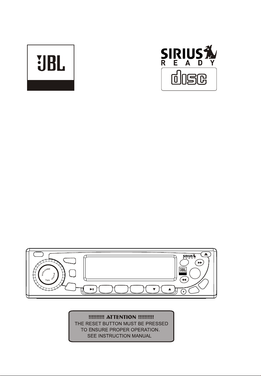
COMPACT
39A-216-100
Form No. 769-04745
MARINE
Operation Manual
PWR
for Users
Model No.: MR-17
MR-17
MODE
SH.
SR
BD/FN
FLIP DOWN / COMPACT DISC PLAYER HI - POWER 4x45Watts
2 INT
3 RPT
1
4 RDM
DIGITAL AUDIO
MUT
MARINE
0. LD
S
P
.
5
7.SCN
6
.A
9
IS
8.D
Page 2

EST.JBL(MR-17)-061205-I/M
¦Ì
Page 3
Contents
Contents
Wiring
Identification
Installing and Removing the Detachable Face
Important Notes
Installation
Supporting the Unit
Identification of Controls and Functions
Controls
Station Tuning
Operating the CD & CD Changer
Precautions and Maintenance
1
2
3
4
5
6
7
8-9
10
11
12
Trouble Shooting Guide & Specifications
PLEASE NOTE: In order to receive Sirius Satellite radio broadcast, you must install
JBL Sir2.5 as well as a satellite antenna (both sold separately).
13
What is SIRIUS Satellite Radio?
SIRIUS, headquartered in New York, offers over 120 cannels of digital quality radio
transmitted across the continental US from three high-tech satellites. Along with offering
a full spectrum of music genres, users can also listen to popular news, entertainment
and sports channels. SIRIUS currently offers 65 music channels, 24 news channels
(including traffic and weather), 7 sports channels (including two dedicated play-by-play
channels) and 24 talk / entertainment channels.
For more information on SIRIUS, visit siriusradio.com.
1
Page 4
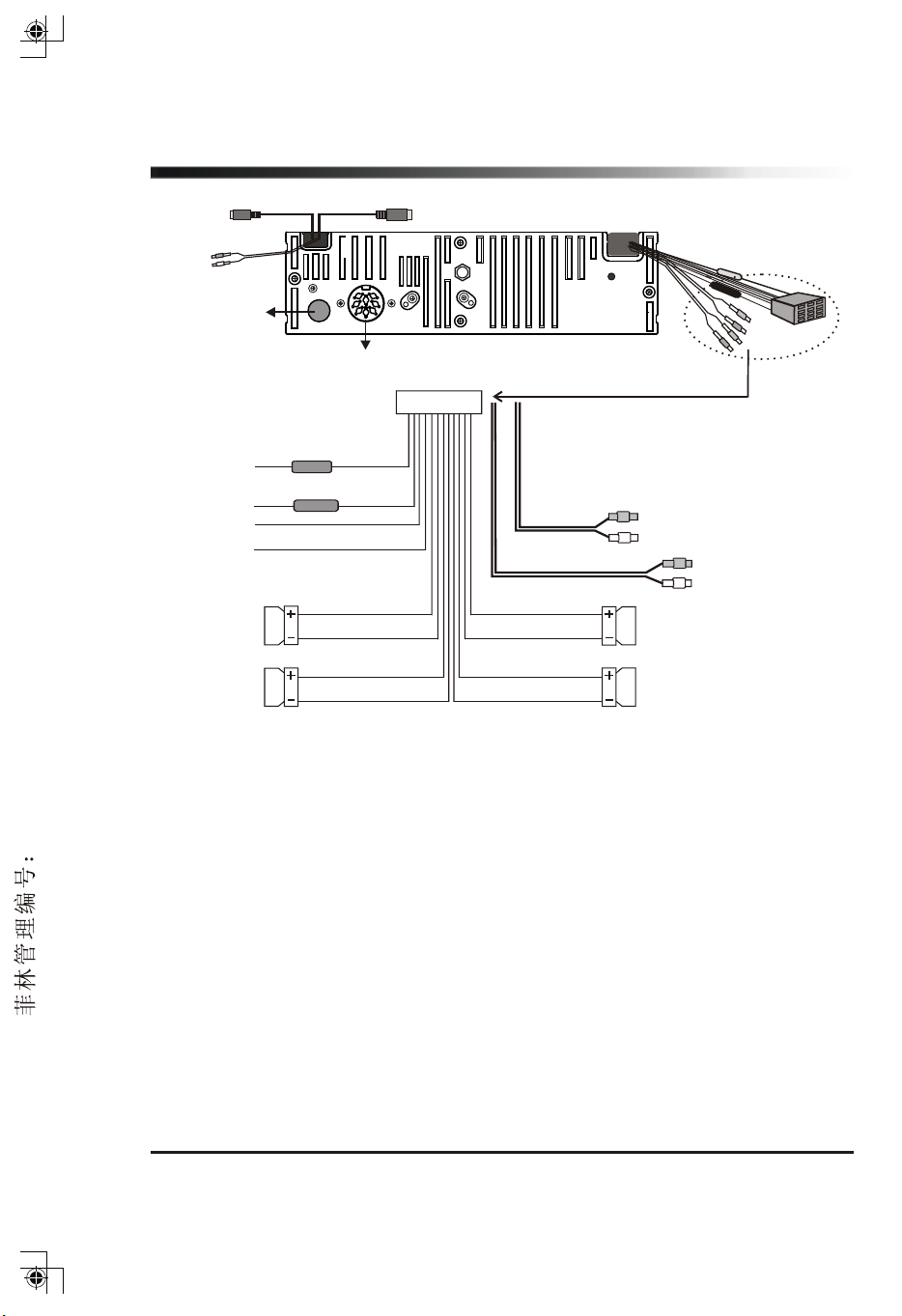
Wiring identification
C
(SIRIUS control)
D
(AUX-IN)
F
(ANT. socket)
(CD changer socket)
E
FUSE
Blue
(AUTO ANT)
( BACK-UP B+ )
( GROUND )
( IGNITION B+ )
( Front Left )
1A
FUSE
10A
Yellow
Black
Red
White
White/Black
(Remote control)
B
CONNECTOR
Gray
Black
Gray
Gray/Black
Red
White
A
Rear Line out
Red
Front Line out
White
( Front Right )
EST.JBL(MR-17)-061205-I/M
( Rear Left )
Green
Green/Black
Violet
Violet/Black
( Rear Right )
Installation Notes
Applicable to both 2 and 4-speaker connection:
A. Connections
B. Din cable connection for remote control
C. Din cable connection for SIRIUS control
D. AUX-IN
E. CD changer socket
F. Antenna socket
This radio contains four separate power amplifiers. To prevent possible damage to
these amplifiers please ensure the following:
i) The boat chassis is not used as a loudspeaker ground(-).
ii) Front and rear loudspeaker connecting wires are not joined together.
iii) Any wires not used when completing a two speaker installation are fully insulated.
iv) The memory wire (yellow) is connected to a permanent + 12V supply.
v) The power wire (red) is connected via the ignition switch of the boat.
2
Page 5
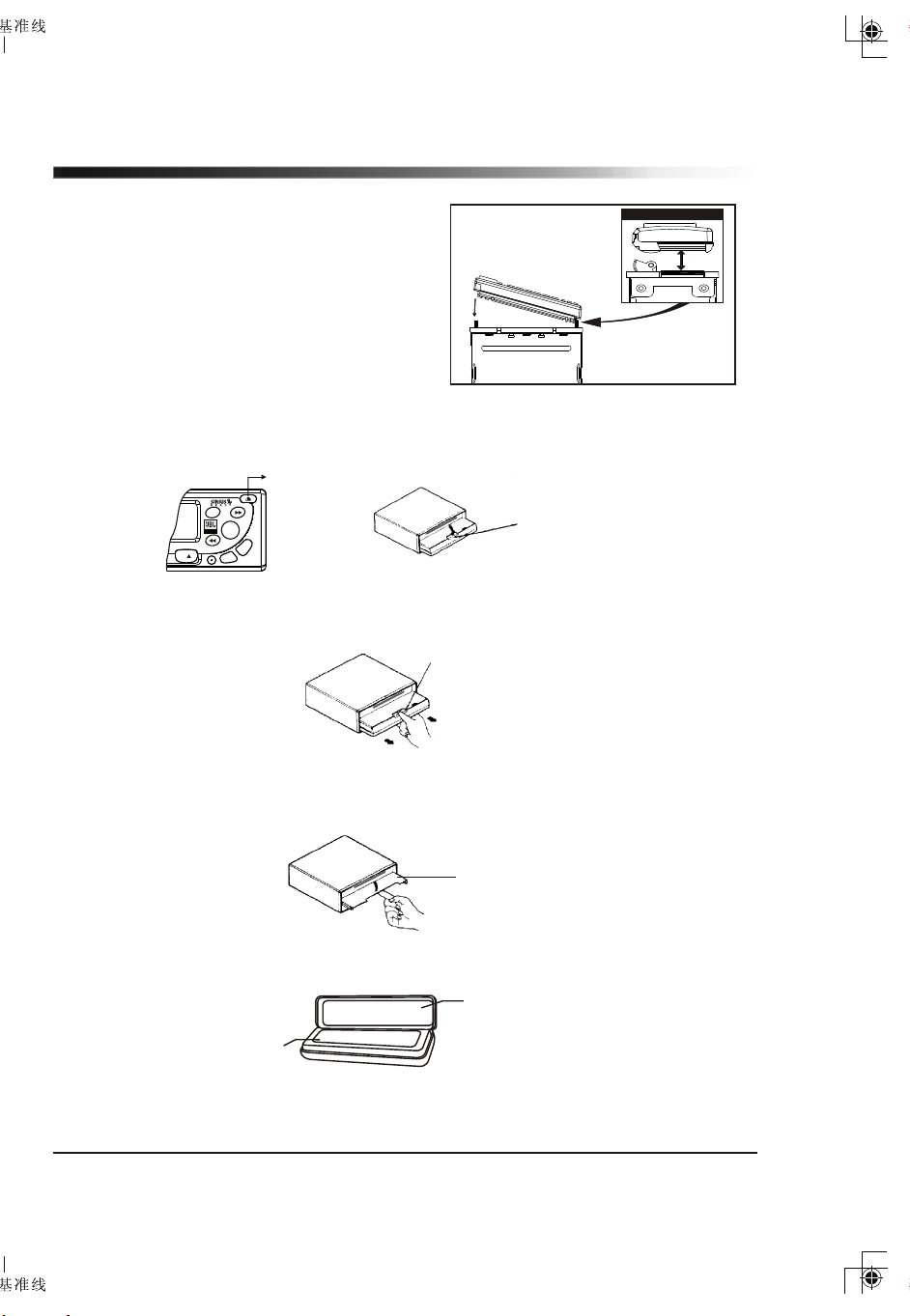
Installing and Removing the Detachable Face
To Install / attach the faceplate:
Close Up of Side View
Place the detachable face place onto
the radio one side at a time so that the
grooved edge of the face plate lines up
directly with the connecting piece on
the radio. The face plate should fit easily
inside the plastic trim. When the face
plate is securely in place, a distinct
“click” will be heard, indicating that it is
locked correctly in place.
To remove the face plate:
1. Press Release button, then the front panel will open (fold down).
Release button
4x45Watts
6
MUT
MARINE
0. LD
S
P
.
A
7.SCN
9.
S
I
D
.
8
Front Panel
2. Grip the release section and pull the front panel forward.
- Be careful not to grip the front panel display too tightly or to drop the panel.
Release section
3. Close the inner cover.
- After removing the front panel, be sure to close the inner cover to prevent dirt,
dust or other foreign matter from entering the CD slot.
Inner Cover
4. Keep the detachable front panel in the protective case provided.
Carrying Case
Front Panel
3
Page 6
Important notes
Prior to the final installation, carry out a sound check. If high distortion or intermittent
sound is experienced, it is possible that the wiring from the CD receiver to the boat's
electrical system is poor or that the battery needs recharging.
If the battery and its charging circuit are OK, then rewire the yellow fused wire of the
CD player directly to the positive terminal (+) of the boat battery.
Marine accessory shops stock the connector blocks and the 10 Amp cable that may
be necessary for extending the fuse wire connection.
Grounding
Make sure that the black wire on the wiring harness is connected to a good ground
point on the boat. If the chassis of the boat is used as a grounding point, make sure
that the surface is scraped clean of paint before attaching the wire to it.
It is preferable to connect the black ground wire directly to negative terminal (-) of
the boat battery.
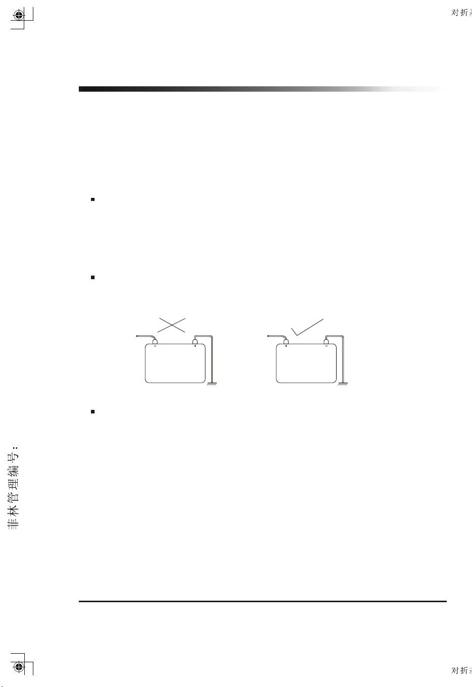
Warning: polarity...
This model is only suitable for use in boats which have a Negative ground system,
e. g. : the negative terminal of the boat battery is connected to the chassis.
EST.JBL(MR-17)-061205-I/M
POSITIVE
CHASSIS
NEGATIVE
CHASSIS
Connecting the Speakers and Power Cables
Before you wire your system, disconnect your boat battery's positive (+) cable.
This helps prevent damage in case of a short. When you complete the wiring,
reconnect the battery cable and test your marine stereo. When connecting your
marine stereo's black ground wire, be sure to connect the wire to a metal part of
your boat or preferably to the negative (-) terminal of the boat battery.
4
Page 7
Installation
1. Precautions
Choose the mounting location carefully so that the unit will not interfere with the
normal driving functions of the boat.
Avoid installing the unit where it would be subject to high temperature, such as from
direct sunlight or hot air, or where it would be subject to dust, dirt or excessive
vibration. Use only the supplied mounting hardware for a safe and secure installation.
Be sure to remove the front panel before installing the unit.
2. Mounting angle adjustment
Adjust the mounting angle to less than 20 degrees from horizontal.
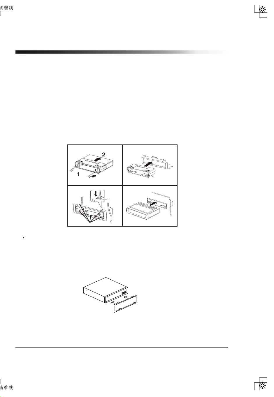
3. Mounting example
<< Installation in the cabinet >>
1 2
Release Key
3
Tap
Bend these claws, if necessary.
4
Half Cabinet
Note: Keep the release key in a safe place as you may need it in future to remove
the unit from the boat.
4. Attaching the Trim Ring
- Attach the Trim Ring to the Radio after installing.
- Be sure to insert the Trim Ring in the correct direction.
5
Page 8
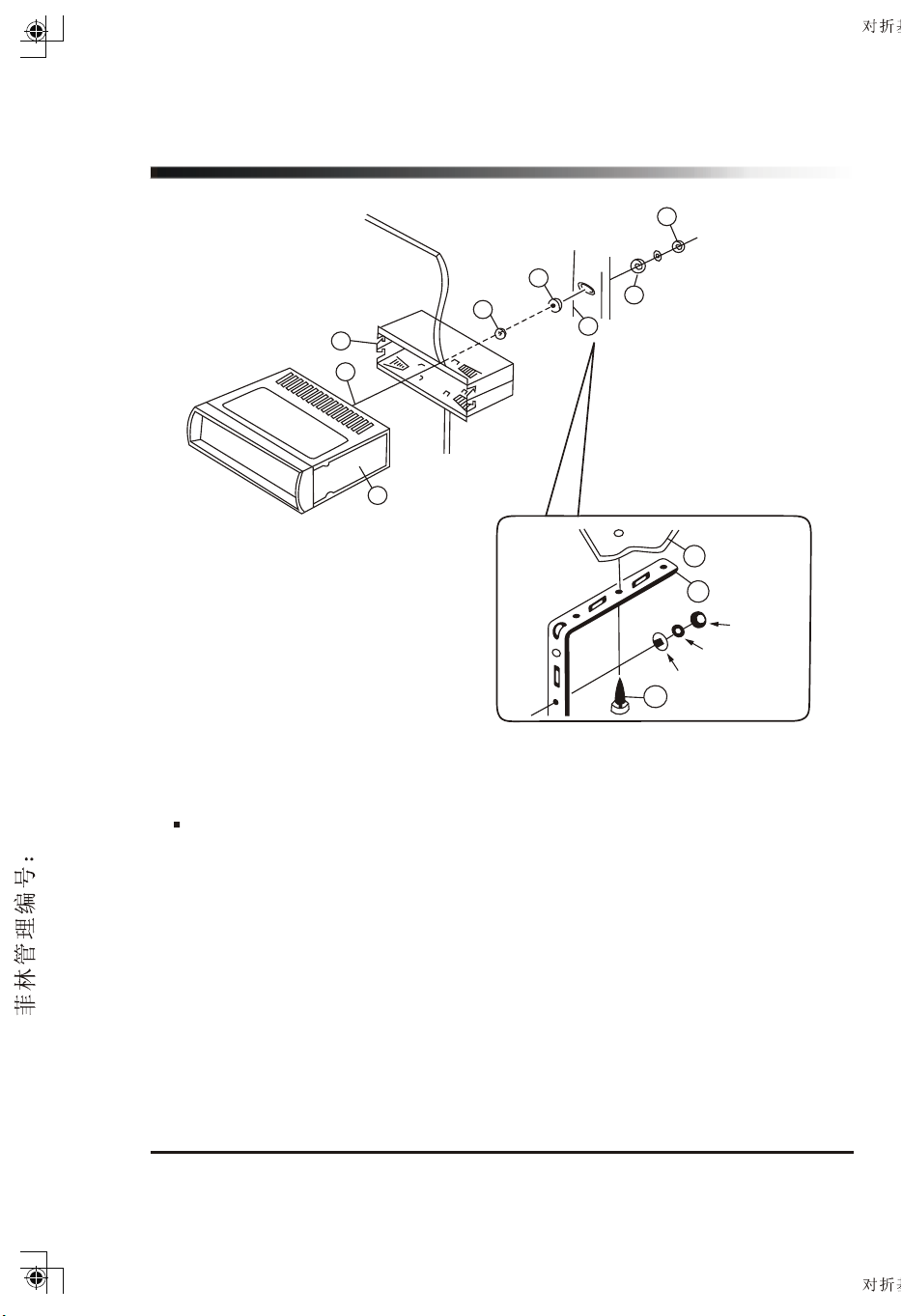
Supporting the unit
3
EST.JBL(MR-17)-061205-I/M
3
4
2
9
1
1. UNIT
2. RELEASE CASE
3. HEX NUT
4. LOCK WASHER
5. PLAIN WASHER
6. BODY
7. REAR SUPPORT STRAP
8. TAPPING SCREW
9. M5 X 20 HEX BOLT
Accessories subject to change without notice.
5
7
6
7
HEX
Lock Wa
sher
Plain
Wa
8
sher
1. Fuse replacement
If the fuse blows, check the power connection and replace the fuse. If the fuse blows
again after the replacement, there may be an internal malfunction. In this case,
consult your nearest dealer.
2. Warning
Use the specified amperage fuse for each lead.
Use of a higher amperage fuse may cause serious damage.
6
Page 9

Identification of controls and functions
1
PWR
2
3
MR-17
MODE
SH.
SR
BD/FN
4
FLIP DOWN / COMPACT DISC PLAYER HI - POWER 4x45Watts
3 RPT
1
2 INT
5
6
7
4 RDM
9
8
5
6
11
10
12
MUT
MARINE
7.SCN
16
13
8
0. LD
.D
17
14
PS
.
A
9.
IS
18
1. POWER ON / OFF button
2. Electronic Function SELECT button, Volume decrease or increase button
3. MODE button <Radio CD CDC SIRIUS AUX-IN>
4. SH. SR (SHIFT / SCROLL) button (SIRIUS only)
5. BD / FN button
6. CD play / pause button, radio preset 1 button
7. CD intro scan button, radio preset 2 button
8. CD repeat track button, radio preset 3 button
9. CD random play button, radio preset 4 button
10. DISC DOWN (CD changer) button, radio preset 5 button
11. DISC UP (CD changer), radio preset 6 button
12. MUTE button
13. LOUD (loudness) button (#0 SIRIUS only)
14. Front panel release button
15. Radio tune UP / DOWN button, CD track UP / DOWN button
16. SCAN button (#7 SIRIUS only)
17. DISP (display) button (#8 SIRIUS only)
18. A.PS - Auto Preset Scan button (#9 SIRIUS only)
15
7
Page 10

Controls
1
PWR
2
3
MR-17
MODE
SH.
SR
BD/FN
4
FLIP DOWN / COMPACT DISC PLAYER HI - POWER 4x45Watts
3 RPT
1
2 INT
6
5
7
4 RDM
9
8
5
6
11
10
12
MUT
MARINE
7.SCN
16
13
0. LD
8
14
15
.PS
A
9.
IS
.D
18
17
1. POWER ON/OFF button (1)
Push the PWR button (1) to turn on the unit. Push the button again to turn off the unit.
2. SEL and VOL button (2)
1) Audio control ( VOLUME / BASS / TREBLE / BALANCE / FADER )
Short pressing the SEL (2) button you can select which of the below features to set:
-VOL display - volume control > press button (2)>
-BAS display - bass tone control >press button (2)>
-TRB display - treble tone control > press button (2)>
-BAL display - balance control > press button (2)>
-FAD display - fader control > press button (2)>
Then use the spindle knob(2) to adjust. In each mode, the waiting time is about 5 seconds.
If the waiting time is over, it returns to the last display mode of Radio, CD, or CDC mode.
These settings are indicated on the display window.
VOLUME Select BASS Select TREBLE
EST.JBL(MR-17)-061205-I/M
Select FADER Select BALANCE Select
2) Beep 2nd , I-Vol , Area and DSP Selection
When the SEL button (2) is pressed over 2 seconds, the unit will be operated as below:
Beep 2nd
Press
I-Vol
Press
Area
Press
DSP
a. Beep 2nd
In the Beep 2nd mode, you can control Beep on or Beep 2nd by turning the spindle knob.
- Beep on : You can hear "beep" sound when you press any buttons.
- Beep 2nd :You can hear "beep" sound when you press a button over 1.5 seconds.
b. I-Vol
By pressing the SEL(2) button again, the unit will turn to I-VOL mode (Initial Volume Level
Adjustment). You can adjust the I-Vol to the level you want by turning the spindle
knob. After setting the initial level, when the unit is powered on/off, detached on/off, or
when the ACC is turned on/off, the I-VOL will keep the volume adjusted to the preset level
when unit is turned on.
8
Page 11

Controls
c. Area Selection
By pressing SEL(2) button again, the unit will be in Area Selection mode, then turn the
knob right or left to choose USA or EUR. Press and hold BD/FN for 2 seconds to confirm
selection.
d. DSP
Choose from flat, classic, pop or rock by pressing the SEL(2) button again. Adjust with
spindle knob.
3.Volume control
Turn the spindle knob (2) left or right to decrease or increase the volume level.
The radio will automatically default to volume mode when powered on.
- Bass control
Turn left to decrease the bass.
Turn right to increase the bass.
- Treble control
Turn left to decrease the treble.
Turn right to increase the treble.
- Balance control
Turn left to decrease the right speaker volume.
Turn right to decrease the left speaker volume.
- Fader control
Turn left to decrease the volume level of any speakers connected to the front channel.
Turn right to decrease the volume level of any speakers connected to the rear channel.
4."MODE" button (3)
Press this button to select Radio, CD, CDC, SIRIUS or AUX-IN.
5. BD/FN button (5)
Press the BD/FN(5) button shortly to select the desired band:FM1,FM2,FM3, AM1
and AM2.
6. SHIFT / SCROLL button (4)
SIRIUS function button only.
7. How to adjust the clock / time (17)
Press DIS(17) button once to display the time.
a. Press and hold the DIS (17) button until the time flashes on the display.
b. Turn spindle knob(2) clockwise to set hour.
c. Turn spindle knob(2) counter clockwise to set minutes.
d. Press the DIS button again quickly to accept the adjusted time.
If no button is pressed within 5 seconds, then it automatically accepts the adjusted
time without further intervention from the user.
8. Loudness function (13)
In order to emphasize the bass and the treble at low volume, press the LD (13) button.
To turn off loudness, press the LD button again.
9
Page 12

Station Tuning
EST.JBL(MR-17)-061205-I/M
1
PWR
2
3
MR-17
MODE
SH.
SR
BD/FN
4
FLIP DOWN / COMPACT DISC PLAYER HI - POWER 4x45Watts
3 RPT
1
2 INT
6
5
7
4 RDM
9
8
5
6
11
10
12
MUT
MARINE
7.SCN
16
13
0. LD
8
14
15
.PS
A
9.
IS
.D
18
17
1. Manual/Seek tuning buttons (15): Press this button quickly to activate the Seek
mode. The Seek mode will automatically seek up or down the wave band and stop at
the next station of sufficient signal strength. Press and hold tuning buttons for 2
seconds to enter manual tuning mode. The unit will revert back to Seek mode after
10 seconds without use.
2. Manual Station store: Select the desired band and tune to a radio station to be
memorized. Choose the preset button memory location1-6 into which the station is
to be stored and press and hold that preset button for 2 seconds.
The station will now be entered into the preset memory. 6 stations can be memorized
on each of the FM1, FM2, FM3, AM1, AM2.
3. A.PS - Auto store function (18)
Press and hold button (18) for approximately 2 seconds until you hear a beep which
confirms the memory function is engaged. The unit will "SEARCH" for six strong
stations and automatically store them on buttons 1 - 6.
You can override the preset station on any button by manually setting a new frequency.
4. Scan (16)
In Radio mode, press the SCAN (16) button to scan strong stations for previewing.
At the desired station press the "SCAN (16)" button again to stop scanning.
5. Program Memory Scan
Momentarily press A.PS and the unit will scan for stored stations.
Momentarily press it again to stop scanning.
10
Page 13

Operating the CD & CD changer
1
PWR
2
3
MR-17
MODE
SH.
SR
BD/FN
4
FLIP DOWN / COMPACT DISC PLAYER HI - POWER 4x45Watts
3 RPT
1
2 INT
5
7
6
4 RDM
9
8
5
10
12
MUT
MARINE
7.SCN
6
11
16
8
13
0. LD
.D
17
14
15
S
P
.
A
9.
IS
18
1. Loading a CD
Open the door by pushing button (14).
Insert a CD label side up into the slot opening, then close the door.
The CD will begin playing automatically after it is loaded.
Notes:
NEVER insert foreign objects into the CD slot opening.
If a CD is difficult to insert, there may already be a CD loaded in the unit.
Some recorded CD-Rs or CD-RWs may not be usable with this CD player.
2. Select the CD->CDC by pressing the "MODE" button (3) .
3. Press preset button (10) or (11) to choose the DISC that you would like to play.
(This button works when you install the CD changer to the radio unit. CDC is optional.)
4. Play / Pause (6)
Push to pause and push again to resume play.
5. Intro Scan (7)
Press this button to hear the first 10 seconds of each track on the disc.
Press this button again to restore the player to its normal play mode.
6. Repeat play button (8)
While playing a desired track, press RPT button to play the track repeatedly.
Press RPT button again to return to normal play mode.
7. Random play button (9)
Press RDM button to play all tracks on a CD in random sequence.
Press RDM button again to return the player to normal mode.
8. Track Tuning (15)
Search the tracks on the DISC with the and buttons. If you press and hold
the or button continuously, the track goes fast - forward or rewinds .
11
Page 14

Precautions and maintenance
1. Reset function
A microprocessor reset button has been provided to facilitate manual resetting of
the internal microprocessor. In the unlikely event that the player fails to operate
correctly refer to step 2 below.
Note: It will be necessary to re-enter the radio preset memories as these will have
been erased when the microprocessor is reset. After resetting the player,
ensure all functions are operating correctly.
CD DISC SLOT
EST.JBL(MR-17)-061205-I/M
CD Eject button
EJ
1
1
2
FRONT PANEL
2. Caution
1
RESET : If you are faced with a malfunction during the operation, simply press
the reset button.
2
CONNECTOR PIN : Always keep connector pin clean.
If the PIN connector looks dirty, use cotton tips to clean it, so as to avoid any
unexpected malfunction caused by dirt.
12
Page 15

Trouble shooting guide
INTERFERENCE ON RADIO
Poor atmospheric conditions - Try again later in the day
Antenna / lead broken or damaged
DISTORTED AUDIO
Check loudspeaker wiring
This product contains a biamp. It is important not to connect the front
loudspeaker ground to the rear speaker ground.
Faulty loudspeaker
Distortion at highest volume levels may be normal, as amplifier has reached
maximum power output. Otherwise the power and ground wire might be too
small of a gauge. Use 10amp cable or more.
Reduce the bass effect or switch off the loudness mode
Boat battery and or charging circuit may be faulty
Specifications
FM TUNER
Tuning Range : 87.5 ~ 107.9MHz(USA)
87.5 ~ 108MHz(EUR)
Sensitivity : 10dB / uV
Separation : 30dB
COMPACT DISC
Freq. Response : 20 Hz-20 KHz
Total Harmonic Distortion : 0.8%
Signal - Noise Ratio : 65 dB
Dynamic Range : 90 dB
AM TUNER (OPTION)
Tuning Range : 530 ~ 1710KHz(USA)
522 ~ 1620KHz(EUR)
Sensitivity : 35dB / uV
AUDIO AMP & GENERAL
Power Output : 4 x 45 watts
Power Supply : DC + 12V
Negative Ground
Speaker Impedance: 4 ohm
13
Page 16

EST.JBL(MR-17)-061205-I/M
This product is sold and serviced exclusively by Prospec Electronics Inc. and must be returned
to Prospec for in and out of warranty repairs. It can not be serviced under warranty by other JBL
service centers. All products sold and serviced exclusively by Prospec Electronics Inc.
For service contact us : 3325 South Morgans Point Road Mt Pleasant SC 29466
Tel 843-849-9037 Fax 843-849-9054
Revised 28 / April / 05
Page 17

Page 18

Page 19

Page 20

Page 21

Page 22

Page 23

Page 24

Page 25

Page 26

 Loading...