

Page 1
Automatic Soldering Irons
for Automation
Ref. TRA245-A / TRA470-A
www.jbctools.com
Page 2
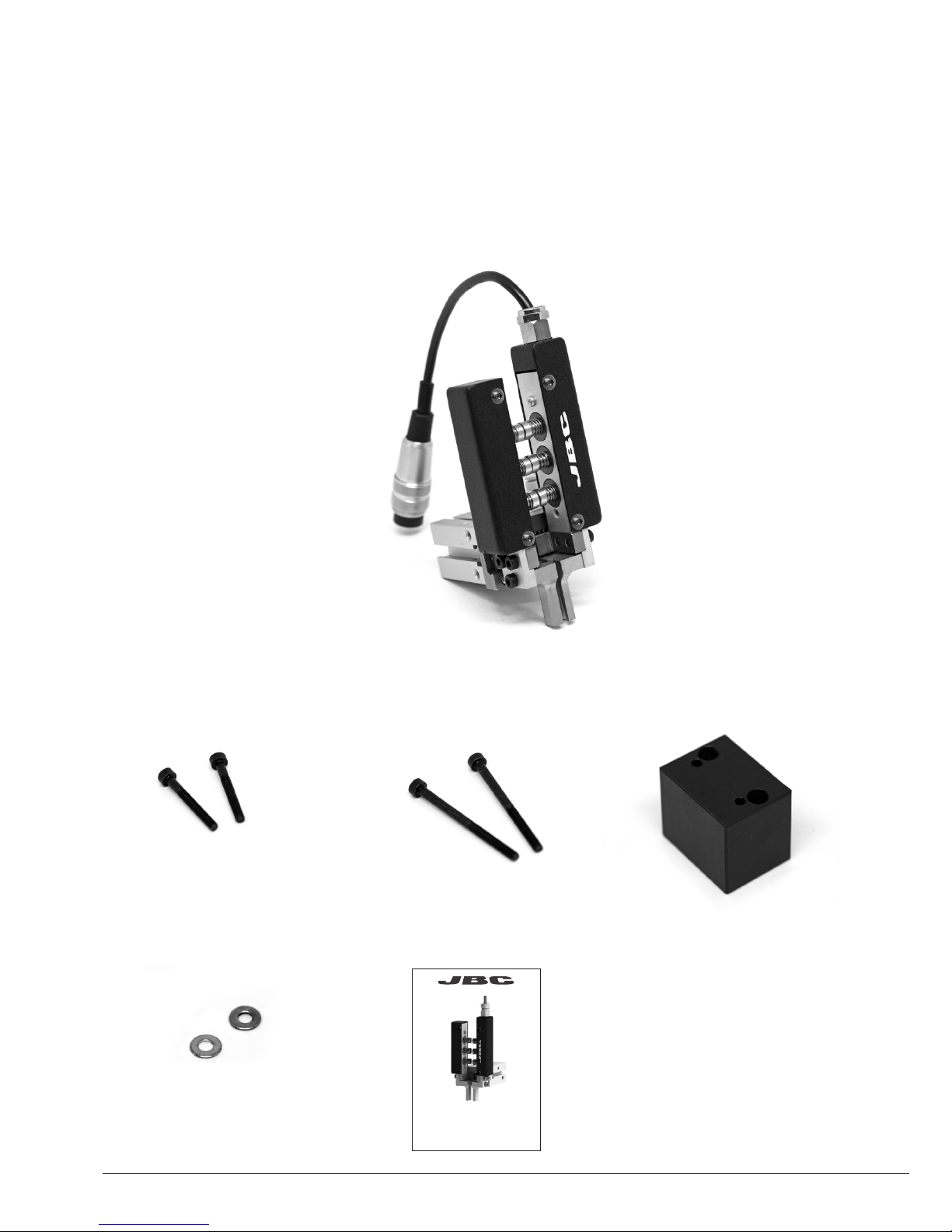
Packing List
The following items should be included for TRA245:
Insulator Clamp ..............1 unit
Ref. 0 021512
Screws
DIN 912 M3X40 .............. 2 units
Ref. 00 21514
Soldering Iron
for Automation .............. 1 unit
Ref. T RA245-A
Works with R245 cartridges
Screws
DIN 912 M3X25 .............. 2 units
Ref. 0001392
Manual ......................... 1 unit
Ref. 0 021282
Washers
DIN 125 Ø3,2 ............ 2 units
Ref. 0242404
Either TRA245 or TRA470 are included.
2
Ref. TR245-A / TR470-A
Automatic Soldering Irons
for Automation
www.jbctools.com
Page 3
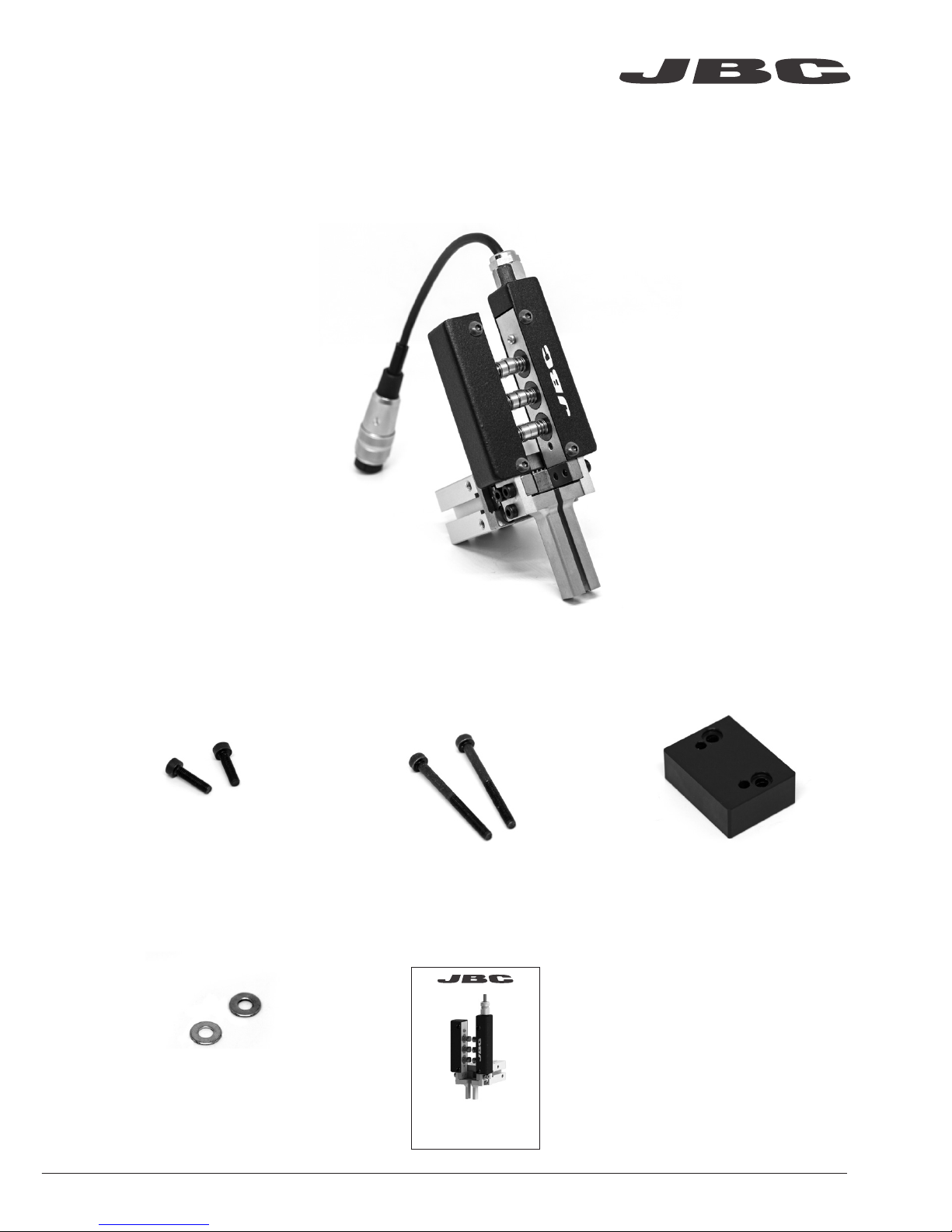
Screws
DIN 912 M3x12 .......... 2 units
Ref. 0926733
Screws
DIN 912 M3x25 ........... 2 units
Re f. 00 21511
Insulator Clamp ..............1 unit
Ref. 0 021513
Washers
DIN 125 Ø3,2 ............ 2 units
Ref. 0242404
Soldering Iron
for Automation .............. 1 unit
Ref. TR A470-A
Works with R470 cartridges
The following items should be included for TRA470:
www.jbctools.com
3
Manual ............................ 1 unit
Ref. 0 021282
Ref. TR245-A / TR470-A
Automatic Soldering Irons
for Automation
www.jbctools.com
Page 4
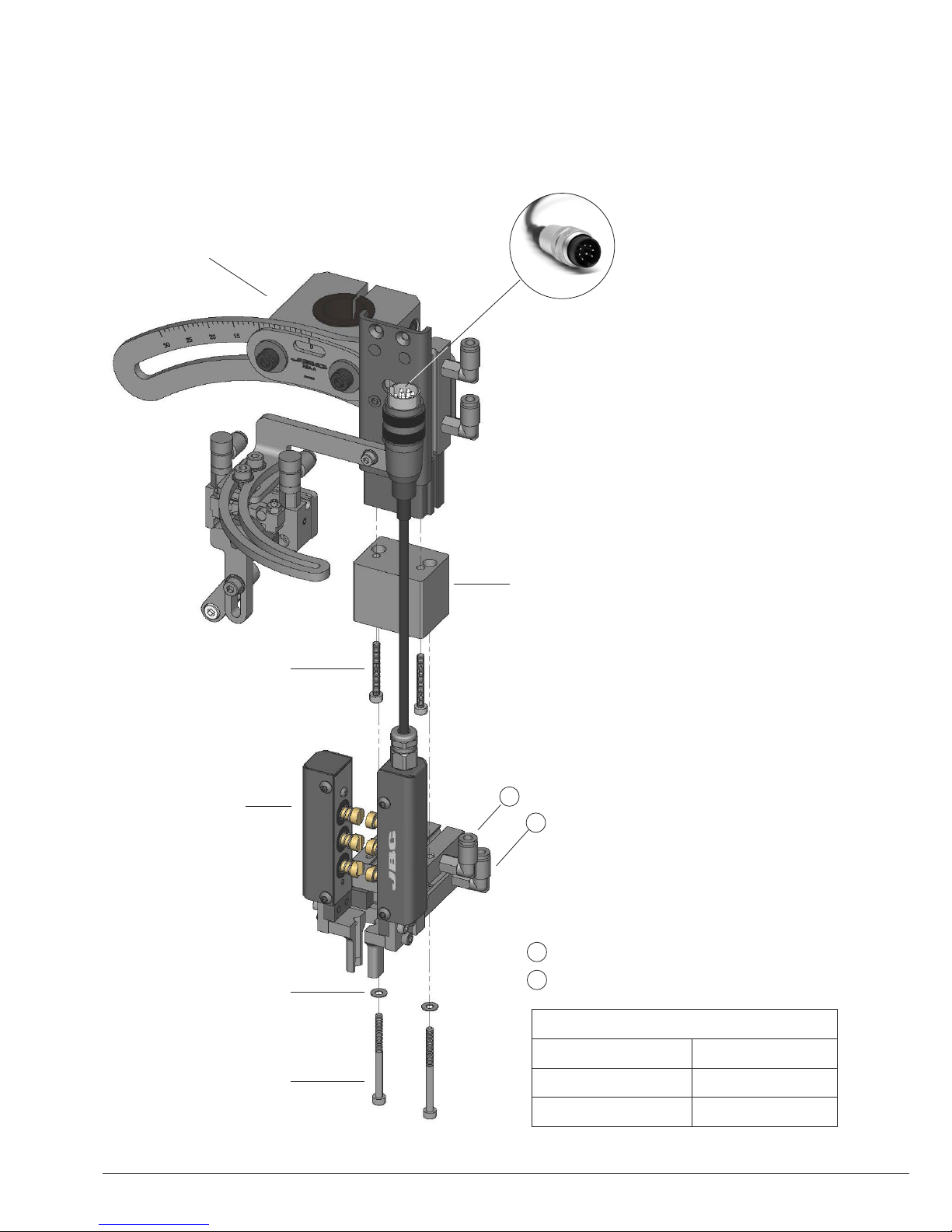
A
B
Assembly
Screws
Ref. 0 021514
Washers
Ref. 024240 4
Automatic
Soldering Iron
Ref. TRA245-A
Screws
Ref. 0001392
Connection to UCR245
using Tool Cable
Ref. 00 2140 3
Gripper Actuator
Fluid Air
Applicable tubing Ø4mm
Operating pressure 0,15 to 0,7 MPa
A Air tube connection to fix cartridges
B Air tube connection to release car tridges
Soldering Head for Automation*
Ref. RBA-A
*Not included, sold separately
TRA245
Insulator Clamp
Ref. 0 021512
It is mandatory to have the electrical
Insulator Clamp assembled for proper
tool working.
Don’t remove the Insulator Clamp.
4
Page 5

Screws
Ref. 0 021511
Washers
Ref. 024240 4
Screws
Ref. 0926733
Automatic
Soldering Iron
Ref. TRA470 -A
A
B
Connection to UCR470
using Tool Cable
Ref. 00 2140 3
Gripper Actuator
Fluid Air
Applicable tubing Ø4mm
Operating pressure 0,15 to 0,7 MPa
A Air tube connection to fix cartridges
B Air tube connection to release car tridges
Soldering Head for Automation*
Ref. RBA-A
*Not included, sold separately
TRA470
Insulator Clamp
Ref. 0 021513
It is mandatory to have the electrical
Insulator Clamp assembled for proper
tool working.
Don’t remove the Insulator Clamp.
www.jbctools.com
5
Page 6

122,1
4,807
~166
~6,535
68,4
2,693
53,5
2,106
40,6
1,598
28
1,102
8,6
0,339
30
1,181
29,8
1,173
15,8
0,622
2x
3,4
2x0,134
21
0,827
15,8
0,622
Working point
TRA245-A
Dimensions
mm
(in)
6
Page 7

138,1
5,437
~166
~6,535
68,4
2,693
69,5
2,736
56,6
2,228
12
0,472
8,6
0,339
30
1,181
29,8
1,173
15,8
0,622
21
0,827
15,8
0,622
2x
3,4
2x0,134
Working point
TRA470-A
mm
(in)
www.jbctools.com
7
Page 8

Inserting Cartridges
The Automatic Soldering Iron for TRA is directed towards the cartridge. Once in position its
valve must be activated.
JBC recommends bi-stable valves to prevent the cartridges from falling out in case of an
emergency stop or power cut.
When using the Automatic Cartridge Stand CS2R, you have to activate its valve to open the
gripper and to release the cartridge before making any movement.
Gripper Actuator
TRA
CS2R*
Soldering
Irons
Cartridge Range Control Unit Cartridge Stand
R245 R470 UCR245 UCR470 CS2R245 CS2R470
TRA245
TRA470
RBA, SFR, GSFR and CLMR are compatible with R245 and R470 ranges.
*Not included, sold separately
Compatibility
8
Page 9

Accessories
Solder Feeder
for Automation*
Ref. SFR-A
Guide Kit
for Automation*
Ref. GSFR
Soldering Head for Automation*
Ref. RBA-A
Automatic
Soldering Iron
Ref. T RA245-A
TR A470-A
Automatic Cartridge Stand*
Ref. CS2R245-A
CS2R470-A
*Not included, sold separately
www.jbctools.com
9
Page 10

*Not included, sold separately
Work Place Example
Solder Feeder*
Ref. SFR-A
Automatic Tip
Cleaner*
Ref. CLMR-A
Soldering Head*
Ref. RBA-A
Automatic Soldering Iron
Ref. TRA245-A
TR A470-A
Automatic Cartridge Stand*
Ref. CS2R245-A
CS2R470-A
Control Unit*
Ref. UCR245-5A
UCR470- 5A
Guide Kit*
Ref. GSFR
10
Page 11

Maintenance
- Before carrying out maintenance, always unplug the tool.
- Use a damp cloth to clean the tool. Alcohol can only be used to clean the metal parts.
- Periodically check that the metal parts of the tool are clean so the control unit can detect the tool
status.
- Periodically check all cables and tube connections.
- Maintain tip surface clean and tinned prior to storage in order to avoid tip oxidation.
Rusty and dirty surfaces reduce heat transfer to the solder joint.
- Replace any defective or damaged pieces. Use original JBC spare parts only.
- Repairs should only be performed by a JBC authorized technical service.
- Under normal operating conditions, the air gripper lifespan is 10 million cycles. It is recommended
to replace it at the end of its lifespan.
It is imperative to follow safety guidelines to prevent electric shock,
injury, fire or explosion.
- Do not use the soldering iron for any purpose other than soldering or rework. Incorrect use may
cause fire.
- The teperature of accessible surfaces may remain high after the unit is turned off.
Handle with care.
- Do not leave the appliance unattended when it is on.
- Be sure that the power supply is disconnected before changing any spare part.
- Allow the cartridges to cool down before changing them.
- Heat can cause inflamable products to ignite even when not visible.
- Avoid flux coming into contact with skin or eyes to prevent irritation.
- Be careful with the fumes produced when soldering.
- Keep your workplace clean and tidy. Wear appropriate protection glasses and gloves when
working to avoid personal harm.
- Utmost care must be taken with liquid tin waste which can cause burns.
Safety
www.jbctools.com
11
Page 12

This product should not be thrown in the garbage.
In accordance with the European directive 2002/96/EC, electronic equipment at the end of their life
must be collected and returned to an authorized recycling facility.
Manual in other languages available on our website
www.jbctools.com
Warranty
JBC’s two-year warranty covers this equipment
against all manufacturing defects, including the
replacement of defective parts and labour.
Warranty does not cover product wear or misuse.
In case of any manufacturing defect, the equipment
must be returned, postage paid, to the dealer where
it was purchased.
0021282-0618-V01
Specifications
TRA245-A
- Net Weight: 316 g (0.69 lb)
- Dimensions: 122.1 x 68.4 x 52.6 mm (4.807 x 2.693 x 2.111 in)
TRA470 -A
- Net Weight: 318 g (0.70 lb)
- Dimensions: 138.1 x 68.4 x 52.6 mm (5.437 x 2.693 x 2.111 in)
Complies with CE standards.
ESD protected.
 Loading...