


www.jbctools.com
INSTRUCTION MANUAL
Complete Rework Station
with Electric Pump
Ref. RMSE-QE

Packing List
The following items are included:
JTSE Control |
|
DDE Control Unit .......... |
1 unit Electric Desoldering |
|
Unit .................................... |
1 unit |
Ref. DDE-1C (120V) |
Module ............................. |
1 unit |
Ref. JTSE-1A (100V - 120V) |
DDE-2C (230V) |
Ref. MSE-A |
|
|
JTSE-2A (230V) |
|
DDE-9C (100V) |
|
|
Stand ................................ |
1 unit Stand ................................ |
1 unit |
Stand ............................... |
1 unit |
Ref. JT-SE |
Ref. AD-SE |
|
Ref. DR-SE |
|
Heater hose set ............ |
1 unit |
General Purpose |
|
Desoldering Iron ........... |
1 unit |
Ref. JT-T1A (100V / 120V) |
Handle .............................. |
1 unit |
Ref. DR560-A |
|
|
JT-T2A (230V) |
|
Ref. T245-A |
|
C560003 already inserted |
|
2

|
|
|
|
|
www.jbctools.com |
|
|
|
|
JT Accessory set |
|
|
|
|
|
Ref. 0012332 |
|
|
|
|
|
||
Extractor stand ............. 1 unit |
|
Extractors |
Tripod |
||
Ref. 0008752 |
|
Ref. E2184 |
Ref. T2050 |
||
|
|
|
|
E2064 |
(Ø 39mm) |
|
|
|
|
E2052 |
T2250 |
|
|
|
|
||
|
|
|
|
|
(Ø 85mm) |
|
|
|
|
Protectors |
Suction Tube |
|
|
|
|
Ref. P2220 |
Ref. 0932330 |
|
|
|
|
P2230 |
|
|
|
|
|
P2235 |
|
|
|
|
|
P4000 |
|
|
|
|
|
P4010 |
|
ESD Tip Cleaner ........... 1 unit |
|
Suction Cups |
Nozzles |
||
Ref. CL8499 |
|
Ref. 0930110 |
Ref. JN2015 (x1) |
||
|
|
|
|
Ø 10 - 0934050 (x3) |
JN2012 (x1) |
|
|
|
|
Ø 4.7 - 0934070 (x1) |
JN2020 (x1) |
|
|
|
|
|
|
Sponge ............................ |
1 unit |
Metal Brush ................... |
1 unit |
Sponge ............................ |
1 unit |
Ref. S0354 |
|
Ref. CL6217 |
|
Ref. CL6210 |
|
3
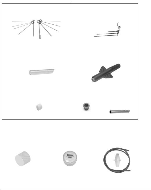
DR560 Accessories
Ref. 0022819
Tip cleaning set ................................. |
1 unit |
Long Tip Cleaning set ..................... |
1 unit |
Ref. 0965970 |
|
Ref. 0965760 |
|
Glass solder collector ..................... |
1 unit |
Spanner ............................................. |
1 unit |
Ref. 0812620 |
|
Ref. 0780550 |
|
Filter Box ................. |
1 unit |
Internal gasket .............. |
1 unit |
Metal solder |
|
Ref. 0780840 |
|
Ref. 0019208 |
|
collector ................... |
1 unit |
It contains 10 filters |
|
It contains 2 gaskets |
|
Ref. 0812630 |
|
Cotton Filter ................... |
1 unit |
Filter Box .......................... |
1 unit |
Suction Filter |
..................1 unit |
Ref. 0781046 |
|
Ref. 0005966 |
|
Ref. 0821830 |
|
It contains 10 filters |
|
It contains 50 filters |
|
|
|
4
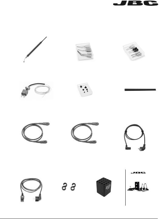
www.jbctools.com
Pick & Place ................... |
1 unit |
Bent Needles Set ......... |
1 unit |
Straight Needles Set ... 1 unit |
Ref. T260-A |
|
Ref. 0861660 |
|
Ref. 0901546 |
Thermocouple |
|
Cups Set ......................... |
1 unit |
Cleaning stick |
................1 unit |
Type K .............................. |
1 unit |
Ref. 0940163 |
|
Ref. 0786640 |
|
Ref. PH218 |
|
|
|
|
|
Stand Cable ................. |
2 units |
Module Cable ................ |
1 unit |
Power cord |
|
Ref. 0011283 |
|
Ref. 0014874 |
|
For DDE ........................... |
1 unit |
|
|
|
|
Ref. 0013671 (100/120V) |
|
|
|
|
|
0010569 (230V) |
|
Power cord |
|
Union |
|
Cartridge |
Manual ................. |
1 unit |
For JTSE ................. |
1 unit |
Flanges ..... |
1 unit |
holder .............. |
1 unit Ref. 0023140 |
|
Ref. 0009417 (100V/120V) |
Ref. 0011356 |
Ref. SCH-A |
|
|
||
0009401 (230V) |
|
|
|
|
|
|
www.jbctools.com
INSTRUCTION MANUAL
Complete Rework Station
with Electric Pump
Ref. RMSE-QE
5

Connections
Work simultaneously with up to 2 tools and join each station port with 1 module + 1 pedal (Peripherals).
Stand Cable
Ref. 0011283 |
|
|
Equipotential connection |
||
|
|
||||
|
|
|
|
USB-B connector |
|
|
|
|
|
||
|
|
|
|
RJ12 connector for Robot |
|
|
|
|
|
||
|
|
|
|
Power Socket |
|
|
|
|
|
|
|
General |
|
|
|
Purpose |
|
|
|
|
|
|
|
Handle |
|
|
Desoldering Iron |
|
|
||
Ref. T245-A |
|
|
Ref. DR560-A |
|
|
|
|
Stand |
Stand |
Ref. AD-SE |
Ref. DR-SE |
6

www.jbctools.com
JTSE Connection
Stand
Ref. JT-SE
Auxiliar connector
Equipotential connector
USB connector
Robot RS232 connector
Power Socket Fuse
To Pedal
Ref. P-005* or P-405*
*Not included
Module Cable
Ref. 0014874
Electric Desoldering Module
Ref. MSE-A
To another peripheral
To Pedal
Ref. P-005* or P-405*
*Not included
7
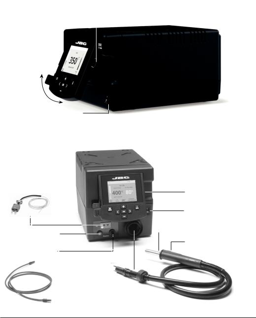
DDE Features
2,8” Color TFT screen |
|
USB-A connector |
||
|
|
|
|
|
|
|
|
|
|
Tilt the display for easy reading
Main switch
JTSE Features
Thermocouple type K
Ref. PH218
USB-A connector
Main Switch
Heating element
Activates the suction pump
Hot Air button
Suction Tube (On / Off) For tripods and extractors
Heater Hose set
Ref. JT-T1A (100V/120V)
JT-T2A (230V)
8

www.jbctools.com
DDE Work Screen
The DDE offers an intuitive user interface which provides quick access to station parameters.
Default PIN: 0105
Status bar |
|
|
|
|
|
|
|
17:14 |
|
|
|
|
|
|
|
|
|
|
Tool |
|||||||
|
|
|
|
|
|
|
|
|
|
|
|
|
|
|
|
|||||||||||
|
|
|
|
|
|
|
|
|
|
|
|
|
|
|
|
|
|
|
|
|
|
|
|
|
|
|
|
|
|
|
|
|
|
|
|
|
|
|
|
|
|
|
|
|
|
|
|
|
|
|
|
|
|
|
|
|
|
|
|
|
|
|
|
|
|
|
|
|
|
|
|
|
|
|
|
|
|
|
|
|
Power |
|
|
|
|
|
T245470 |
|
|||||||||||||||||||
|
|
|
|
|
|
|
|
|
|
|
|
|||||||||||||||
|
|
|
|
|
|
|
|
|
|
|
|
|||||||||||||||
|
|
|
35080ºC |
|
|
|
|
|
|
in use |
||||||||||||||||
|
|
|
|
|
|
|
|
|
|
|
|
|
|
|
|
|
|
|
|
|
|
|
|
|
|
|
|
|
|
|
|
|
|
|
|
|
|
|
|
|
|
|
|
|
|
|
|||||||
|
|
|
|
|
|
|
|
|
|
|
|
|
|
|
|
|
|
|
||||||||
indicator |
|
|
|
|
|
|
|
|
|
Temp. Levels |
|
|
|
|
|
|
|
|
|
|
|
|||||
|
|
|
|
|
|
|
|
|
|
250 350 380 |
|
|
|
|
|
|
|
|
|
|||||||
|
|
|
|
|
|
|
Power |
|
Port |
|
|
|
|
|
|
|
||||||||||
Displayed if |
45% |
|
|
|
1 |
|
|
|
|
|
|
|
|
|
||||||||||||
temperature |
|
|
|
|
|
|
|
|
|
|
|
|
|
|
|
|
|
|
|
|
||||||
|
|
|
|
|
|
|
|
|
|
|
|
|
|
|
|
|
|
|
|
|||||||
levels are |
|
|
|
|
|
|
|
|
|
|
|
|
|
|
|
|
|
|
|
|
|
|
||||
|
|
|
|
|
|
|
|
|
|
|
|
|
|
|
|
|
|
|
|
|
||||||
activated |
|
|
|
|
|
|
|
|
|
|
|
|
|
|
|
|
|
|
Station |
|||||||
|
|
|
|
|
|
|
|
|
|
|
|
|
|
|
|
|
|
|
|
|
|
|
|
|
||
|
|
|
|
|
|
|
|
|
|
|
|
|
|
|
|
|
|
|
|
|
|
|
|
|
||
|
|
|
|
|
|
|
|
|
|
|
|
|
|
|
|
|
|
|
|
|
||||||
|
|
|
|
|
|
|
|
|
|
|
|
|
|
|
|
|
|
|
|
|
||||||
|
|
|
|
|
|
|
|
|
|
|
|
|
|
|
|
|
|
|
|
|
|
|
|
|
Information |
|
|
|
|
|
|
|
|
|
|
|
|
|
|
|
|
|
|
|
|
|
|
|
|
|
|
Change |
|
|
|
|
|
|
|
|
|
|
|
|
|
|
|
|
|
|
|
|
|
|
|
|
|
|
||
|
|
|
|
|
|
|
|
|
|
|
|
|
|
|
|
|
|
|
|
|
|
|
|
|
||
|
|
|
|
|
|
|
|
|
|
|
|
|
|
|
|
|
|
|
|
|
|
|
|
|
port |
|
|
|
|
|
|
|
|
|
|
|
|
|
|
|
|
|
|
|
|
|
|
|
|
|
|
|
|
|
|
|
|
|
|
|
|
|
|
|
|
|
|
|
|
|
|
|
|
|
|
|
|
|
|
|
|
|
|
|
|
|
|
|
|
|
|
|
|
|
|
|
|
|
|
|
|
|
|
|
|
|
|
Menu Options
Set the station |
Set the tool |
|
Display the hours |
parameters |
parameters |
|
worked in each cycle |
Station |
Tools |
Counters |
|
Consult / modify the |
|
|
|
links of the peripherals |
It is possible to |
|
Allows you to carry |
connected to the |
choose the language |
|
out an overall station |
station with the port |
from a list. |
|
reset restoring all the |
they are connected to. |
|
|
parameters to their |
Peripherals |
Language |
Reset |
default values. |
9
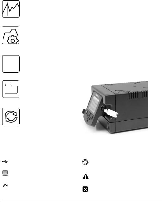
Advanced functionalities
It provides detailed graphics of tip temperature and power delivery in real time during solder joint formation for analysis purposes. This helps you decide how to adjust your process or which tip to use to obtain the best quality soldering.
Graphics
|
Designed to avoid thermal shock when soldering Ceramic Chip components like |
|
MLCC, this new and unique feature allows controlling the heating ramp up rate of the |
|
tool to gradually increase the temperature of the |
|
component through all the phases of the soldering process. Up to 25 fully confi gurable |
Profiles |
soldering profi les can be stored. |
The first system to optimize traceability in soldering
JBC Net - Get greater quality and control in your production
- Manage your whole soldering process remotely in real time
Export graphics
Insert a USB flash drive into the USB-A connector to save your
soldering process in csv format.
Files
Station update
Download the JBC Update File from
www.jbctools.com/software.html
Insert the USB flash drive with the
Update file downloadedto the station.
System notifications
The following icons will be displayed on the screen’s status bar.
USB fl ash drive is connected. |
Station software update. |
|
Press INFO to start the process. |
Station is controlled by a PC. |
Warning. |
|
Press INFO for failure description. |
Station is controlled by a robot. |
Error. |
|
Press INFO for failure description, |
|
the type of error and how to proceed. |
10
 Loading...