

Page 1

Reference Guide
TI-A
THERMOMETER
FOR SOLDERING IRONS
www.jbctools.com
Page 2
2
TI-A / THERMOMETER FOR SOLDERING IRONS
CONTENTS
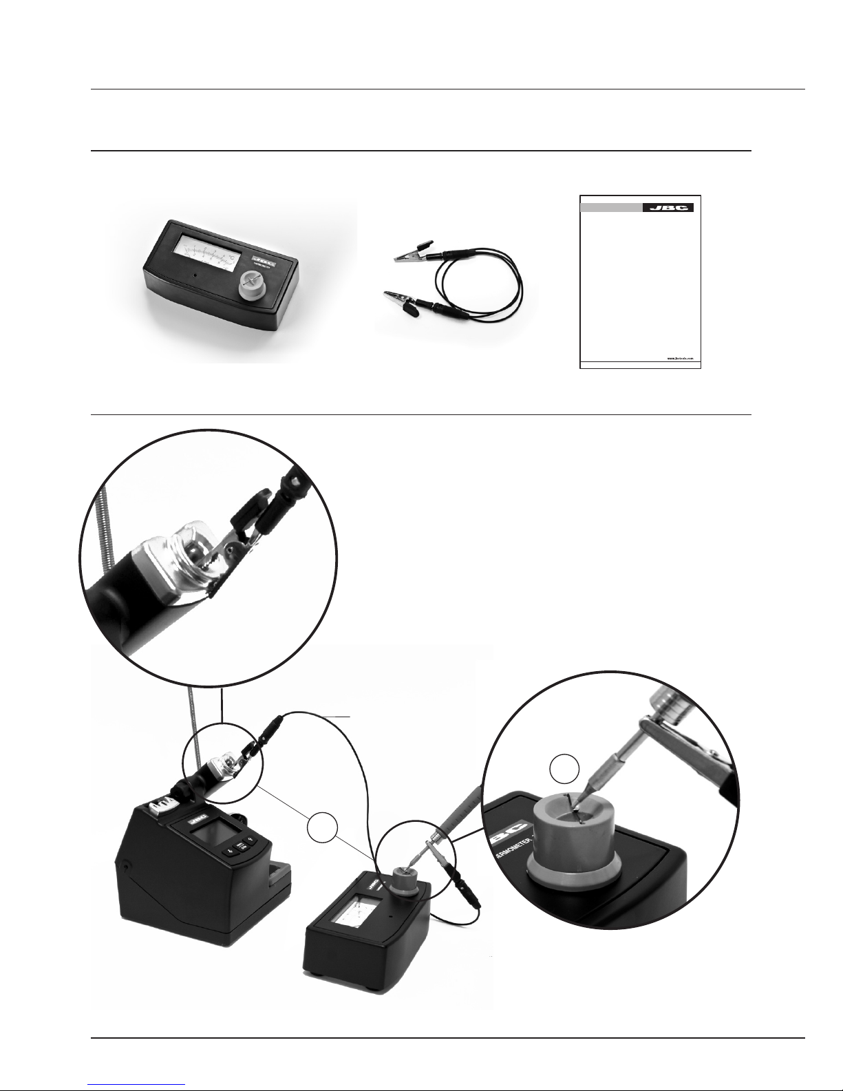
CHECKING THE SLEEP TEMPERATURE
Reference Guide
TI-A
THERMOMETER
0780476
CABLE CONNECTOR
MANUAL
1. Connect the ends of the cable to the metal parts of
the stand and the handpiece.
2. The soldering tip must be well tinned.
3. Apply solder in the center of the sensor.
4. Wait a moment until the read temperature stabilizes.
5. Read the temperature.
0780476
CABLE CONNECTOR
1
3
TI-A
THERMOMETER
FOR SOLDERING IRONS
Page 3

3
CALIBRATION OF TI-A
Pull out the sensor ST-A
Adjust at an ambient temperature
with slotted screw driver.
Wiring like the drawing below.
Apply a voltage of 23.65mV and verify the temperature shown in the thermometer is 350°C
(662°F)
Take note of the deviation to correct future measurements.
Insert the sensor ST-A.
NOTE: Thermometer can be adjusted through the potentiometer you will find inside the unit.
Digital
mVolt Meter
TI-A
Variable
power supply
ST-A
1
2
3
4
5
6
+
-
- -+ +
1
2
Page 4

0780917/0311
WARRANTY
The JBC 2 years warranty, guarantees this equipment against all
manufacturing defects, covering the replacement of defective parts
and all necessary labour.
Warranty does not cover product wear due to use or mis-use.
In order for the warranty to be valid, equipment must be returned,
postage paid, to the dealer where it was purchased enclosing this,
fully filled in, sheet.
MORE INFORMATION
www.jbctools.com
SERIAL Nº
STAMP OF DEALER
DATE OF PURCHASE
THECNICAL SPECIFICATIONS
- Temperature range from 20 to 500°C (68-920° F) (±5%).
- Type of thermocouple: E (NiCr-CuNi)
- Ambient temperature correction: Fixed at 20°C (68° F)
- Display resolution: 10°C (20°F)
- Total weight of unit: 0.9Kg.
- Complies with CE standards on electrical safety, electromagnetic compatibility and ESD protected housing
“skin effect”.
- RoHS compliant.
This product should not be
thrown in the garbage.
 Loading...