

Page 1
English
www.jbctools.com
Precision Hot Air Station
Ref. TE-C
www.jbctools.com
Page 2
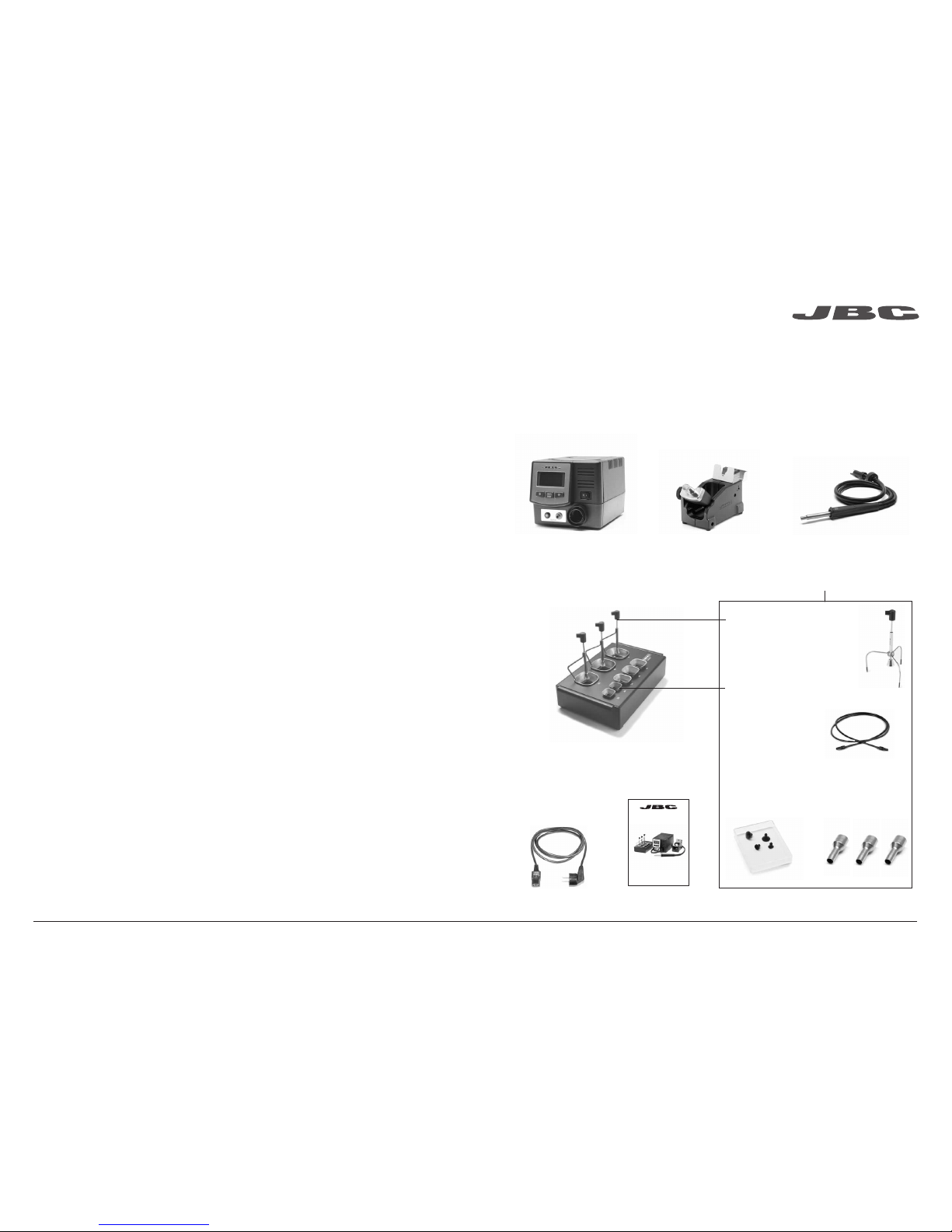
Packing List
The followin g items should be i ncluded:
Accessory set
Ref. 0012332
2 3
Manual .............1 unit
Ref. 0015898
* Not supplie d with TE-QC
www.jbctools.com
Power Cord .....1 unit
Ref. 0009417
(100V/120V)
0009401
(230V)
Precision Hot Air Station
Ref. TE-C
Precisio n Heater
hose set ............................1 u nit
Ref. TE-TB
Stand ..................................1 unit
Ref. TE-SA
JTE Contro l Unit ............1 unit
Ref. JTE-1C
JTE-2C
JTE-9C
Extra ctor desk* ..............................................1 unit
Ref. 0008752
Suction Tube*
Ref. 0932330
Suction Cups*
Ref. 0930110
Ø 10 - 0934050 (x3)
Ø 4.7 - 0934070 (x1)
Extra ctors*
Ref. E2184
E2064
E2052
Protector s*
Ref. P2220
P2230
P2235
P4000
P4010
Tripod*
Ref. T2050
T2250
Nozzles
Ref. TN9209 Ø 3mm
TN9208 Ø 4mm
TN9080 Ø 5m m
2
ww w.jb ct oo ls. co m
3
Page 3
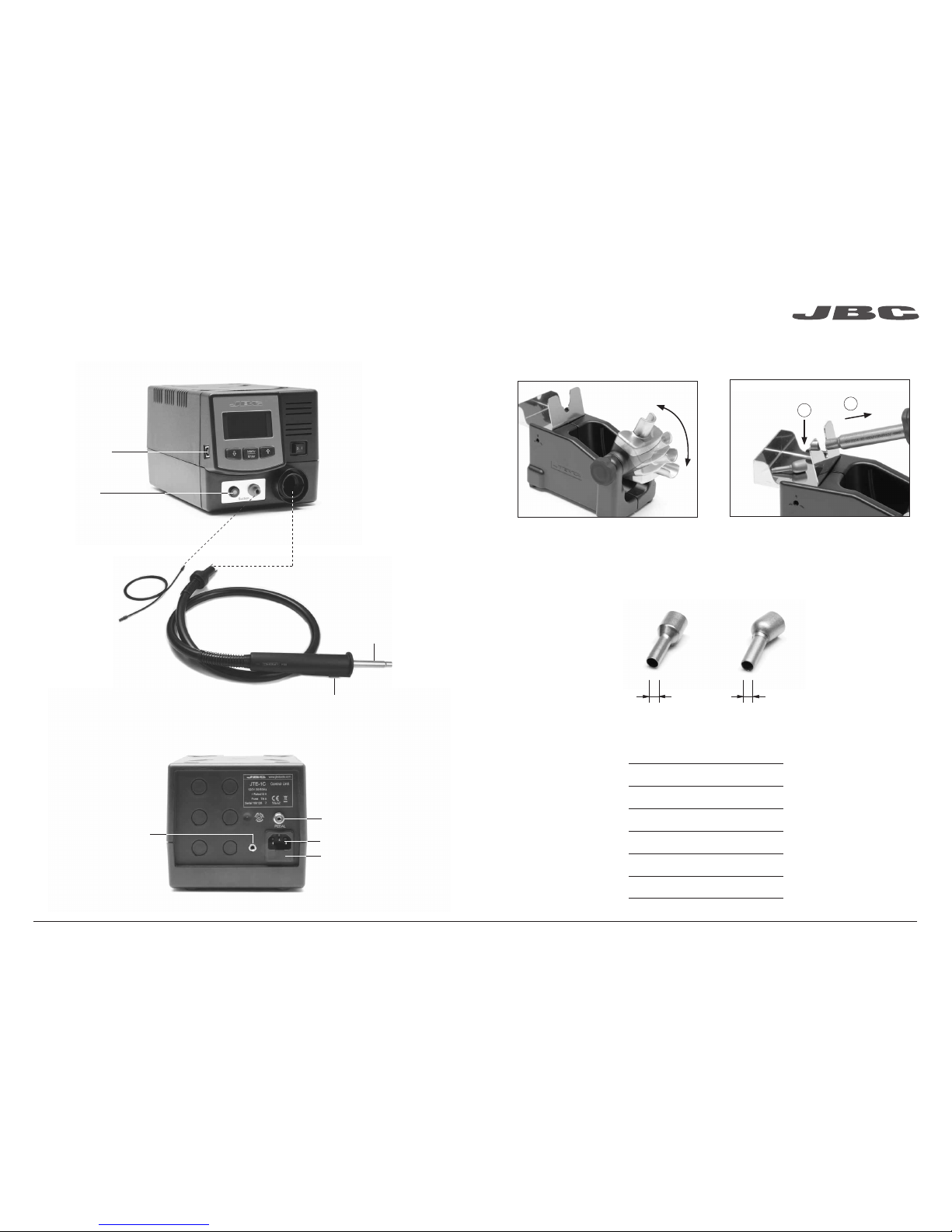
Features
Compatible Nozzles
The TE-TB works with TE nozzles. Find the model that best suits your soldering needs in www.jbctools.com
2
1
4 5
Other connectable tool:
Heater hose set
Ref: JT-TA
Hot Air switch
(On / Off )
Power Socket
Fuse
Equipotentia l
connectio n
To Pedal
Ref. P-005
Press the pedal to start
hot air or rele ase to stop.
Heating
element
Precisio n Heater
Hose set
Ref. TE-TB
Suction Tube
Ref. 0932330
For tripods
and extractors
Activates the
suction pump
USB-B co nnector
Update the station
softwar e from
the JBC website
Suits your work p osition
Adjustable Stand Nozzle Changer
Nozzle ch anger
Ref. Shape Size
TN9209 Straight Ø 3mm
TN9208 Straight Ø 4mm
TN9080 Straight Ø 5mm
TN9787 Bent Ø 3mm
TN9785 Bent Ø 4mm
TN9782 Bent Ø 5mm
Straight Bent
Ø mm Ø mm
4
ww w.jb ct oo ls. co m
5
Page 4

Te mp ºC
Ai r %
Time to stop 45 seconds
Power 70%
400
85
400ºC Select
Operation
Process Control
3. Releasing1. Placing 2. Heating
For small components
(fig. 1 and 2). For large components (fig. 3 an d 4).
6 7
Position the ex tractor with the
appropria te suction cup and
press the suc tion button.
Heat the comp onent by
pressing th e heater button.
The compon ent lifts of f
automatical ly when the
solder mel ts.
Access Menu ( pess key 2 seconds) & Con firm Select ion
Selected te mperature
Current tempe rature
% Instant power su pplied
to heater
You can switch betwe en operating mo des (Manual Mode / Program Mode) by pre ssing the
“increase” a nd “decrease” keys sim ultaneously f or 2 seconds (Onl y when programs mo de is ON).
Manual Mode
We recommend u sing the protector + tri pod We recommend using the extrac tors
Protectors & Extractors
1 2 3 4
Protector s
* Ref. AxB (m m) * Ref. AxB (mm)
P3353 4,3 x 3
48
P2230 15 x 15
P3786 5,2 x 5,2
60
P4010 17 x 17
P3352 5,2 x 7,5 P4005 18 x 29
P3355 5,2 x 9,5 P4030 18,5 x 18,5
P3356 6,2 x 4,2 P1068 18,5 x 24
P3785 7, 2 x 7,2 P26 85 28,5 x 28,5
P3784 8,2 x 8,2 P4085 31,5 x 31,5
P4035 9 x 13 P2672 33 x 46
P4040 9,5 x 19 P4002 50 x 50
P4080 9,5 x 21 P3357 52,5 x 14
32
P2220 10 x 10
P4045 10,5 x 21
P4090 11 x 16
24
P2235 12 x 17
P1249 12 x 23
44
P4000 12,5 x 12,5
P3354 13,2 x 13,2
P4025 13,5 x 21,5
øD
* Referenc e Desk
Tripods
* Ref. øC (mm)
T2050 39
T2250 85
Manua l extrac tor
* Ref. øD (mm)
E2190 7
Extra ctors
* Ref. AxB (mm) * Ref. AxB (mm)
52 E2052 20 X 20 E2124 45 X 45
64 E20 64 20 X 26
80 E2184 24 X 24
E2068 27 X 27
E4020 28,5 X 28,5
E4015 31,5 X 31,5
E2084 33 X 33
E2100 38 X 38
Current air flow
6
ww w.jb ct oo ls. co m
7
Page 5

Ma in m en u
1 Reset settings
2 Station
Settings
3
Program Settings
4
Counters
5 Program version
Ex it
Se tt in gs Pr og ra m Se tt in gs
Ed it P ro gr am
Ed it P ro gr am 8
1
Temp unit Celsius
2 Maximum
temp 4500C
3 Minimum temp T OFF*
4 Fix temp 4000C
5 Temp Adjust 00C
6 Max air 100%
7 Min air 10%
8 Fix air 40%
9 Time to stop 120 sec
10 Beep ON
11 Pop up ON
12 Change PIN
1 Programs
2 Edit program
3
Copy program
4
Delete program
Ba ck
Se le ct
Pr og ra m
St ep 4
Ti me 20
Te mp 45 0
Ai r 10 0
º
C
º
C
8
Ex it
Co un te rs
1 Station ON hours
0
2
Works hours 0
3 Works
cycles 0
Ba ck
Te mp ºC
º
C
Pr og ra m 8
380
Air 100%
Time 125s.
8 9
* Selecting M inimum Temp as
“T OFF”, the air blows at room
temperature.
Menu Screen
Original PIN: 0105
Decrease p rogram
number
Increase program
number
Selected pr ogram
Current temp erature
Selected air flow
Graph of sel ected
program
Remaini ng time
Program Mode
Edit Progr am
This option al lows you to edit or create a program.
First, you must se lect the progra m to edit and then mo dify the points that make up the progr am.
Each progra m is composed of 9 po ints, each point co nsisting of 3 para meters:
1. Time (seconds)
2. Temperature (°C / °F)
3. Flow rate (%)
You can delete the last po int of the program by se lecting “-----” in the time pa rameter.
Remembe r that the regulatio n range permi tted by the station is b etween 150°C and 450°C, so it is
not possibl e to create temperature ramps between ro om temperature ( T O FF ) and 150°C.
The station c an store up to 25 temperature pr ograms.
The first th ree programs are installed as an ex ample.
Copy Progr am
This option al lows you to copy a program.
You must select the pro gram source and its destination (w here it will be co pied).
Delete Program
This option wi ll allow you to delete a prev iously sele cted program.
8
ww w.jb ct oo ls. co m
9
Page 6

Choose the needle and the suction cup that best fits the component and start working as follows:
Maximum working temp: 250ºC (482ºF)
Operati on
1. Suction
Pick & Place
Ref. T260-A
2. Relea se
This tool helps you easily place and remove SMDs of any size thanks to the suction pump.
Pick & Place (not supplied with TE)
Press the button to
start/stop the suction
Once the suction is
activated, cover the
pen hole with your
finger and lift off the
component.
Insert the needle
with the appropriate
cup for a correct
suction process.
Lift your finger
to release the
component in the
appropriate place.
You should
avoid the needle
protruding from the
lower part.
Pick & Place
Ref. T260-A
Straig ht Needles Se t
Ref. 0901546
Bent Need les Set
Ref. 0861660
10 11
Only per form this operation when the element is cold an d the unit is disco nnected from the m ains.
1. Loosen the screw.
2. Pull the he ating element away f rom the handle.
3. Connec t the new heating el ement, ensuri ng it is pushed al l the way in.
4. Tighten the sc rew.
Replacing the Heating Element
1. Ensure that the tool is tur ned off.
2. Use a spann er to unscrew the con necting nut.
3. When att aching the new tub e make sure the rib
lines up with th e groove on the control u nit.
4. Tighten wit h the spanner.
Changing the TE-TB Precision Heater Hose Set
Precisio n Heater
Hose Set
Ref. TE-TB
Heating El ement
Ref. 0012374 (100V - 230V - 120V)
Handle
Ref. 0012697
10
ww w.jb ct oo ls. co m
11
Page 7

Safety
It is imperative to follow safe ty guideli nes to prevent ele ctric
shock, inj ury, fire or expl osion.
- Do not use the uni ts for any purpose other than solde ring or rework. Inc orrect use may c ause fire.
- The power cord must be plugged into approved bases. Be sure that it is properly grounded
before use. When unp lugging it, hold th e plug, not the wire.
- Do not work on ele ctrically li ve parts.
- The tool should be placed in the s tand when not in us e in order to activate the sleep mode.
The s oldering tip, the me tal part of the tool a nd the stand may stil l be hot even when the s tation is
turn ed off. Handle wi th care, includin g when adjustin g the stand positi on.
- Do not leave the ap pliance unat tended when it i s on.
- Do not cover the ven tilation grills. H eat can cause i nflamable products to ignite.
- Use a “non resid ue” classifi ed flux and avoid c ontact with skin or eyes to prevent irritation.
- Be careful with the fumes prod uced when sol dering.
- Keep your work place clean a nd tidy. Wear appropria te protective glasse s and gloves whe n
work ing to avoid person al harm.
- Utmost care mu st be taken with liq uid tin waste which c an cause burn s.
- This appli ance can be use d by children over the a ge of eight and als o persons with re duced
physi cal, sensor y or mental capabilities or la ck of experienc e provided that they have been given
adeq uate superv ision or instru ction concer ning use of the appliance and und erstand the ha zards
involved. Children mus t not play with the app liance.
- Maintenanc e must not be carr ied out by childr en unless sup ervised.
1. Pull off the fuse holder and remove th e
fuse. If nece ssary use a too l to lever it off.
2. Press the new fuse into the fuse ho lder
and replace i t in the station.
Fuse holder
Fuse holder
Fuse
12 13
Maintenance
Before carr ying out mai ntenance or storag e, always allow the equipment to cool.
- Clean the station screen with a g lass cleane r or a damp cloth.
- Use a damp cloth to cl ean the casing a nd the tool. Alcohol can only be use d to clean
the metal pa rts.
- Maintain he ating elemen t clean prior to storage in order to avoid its oxi dation.
Rusty and dirty sur faces redu ce heat transfer.
- Periodica lly check all c ables and tubes.
- Replace a bl own fuse as follows:
- Replace any d efective or dama ged pieces. Us e original JBC s pare parts on ly.
- Repairs sh ould only be performed by a JBC a uthorized techn ical serv ice.
12
ww w.jb ct oo ls. co m
13
Page 8

14 15
Exploded View
TE-1C 120V 50/60Hz. Input fus e 8A. Rated Current 6A. Control Unit m odel: JTE-1C
TE-2C 230V 50/60Hz. Inpu t fuse 4A. Rated Cur rent 3A. Control U nit model: JTE-2C
TE-9C 100V 50/60Hz. Inp ut fuse 8A. Rated Cu rrent 7A. Control Unit mod el: JTE-9C
- Weigh t: 5.2 kg (11.4 lb)
- Dim ensions: 148 x 184 x 140
- Nom inal Power: 300W
- Temperatur e selection: Room te mperature / 150ºC to 450°C (300ºF to 840 ºF)
Cool m ode: T Off. Used to blow ai r at room temperature
- Amb ient Operatin g Temperature: 10 to 40ºC (50-104ºF)
- Idle Temp. Stabilit y: +/-20 ºC (+/-36 º F)
- Air f low regulation: 3-17 SLPM
- USB co nnector station -PC
- P-0 05 Pedal conne ctor
Complies w ith CE standard s
ESD protected hous ing “skin effe ct”
Specifications
14
ww w.jb ct oo ls. co m
15
Page 9

0015898-0215
www.jbctools.com
Warranty
JBC’s 2 year warranty covers this equipment
against all manufacturing defects, including the
replacement of defective parts and labour.
Warranty does not cover product wear due to use
or mis-use.
In order for the warranty to be valid, equipment
must be returned, postage paid, to the dealer
where it was purchased.
This product should not be thrown in the garbage.
In accordance with the European directive 2002/96/EC, electronic equipment at the end of their life
must be collected and returned to an authorized recycling facility.
 Loading...