

Page 1
Index Page
English 1
Español 6
Français 11
Deutsch 16
Italiano 21
Instructions manual
TA 5120
RA 5150
A N A L O G U E R E P A I R S T A T I O N S
Page 2

Page 3

1
ENGLISH
We appreciate the trust you have shown in JBC by purchasing this station.
It has been manufactured with the highest standards of quality to ensure reliable
service. Before starting up the apparatus, we recommend you read these instructions
carefully.
FEATURES
Station composition
RA 5150 EU: Ref. 5150200
RA 5150 UK: Ref. 5150201
RA 5150 USA: Ref. 5150100
- Control Unit 230V Ref. 5330200
- Control Unit 120V Ref. 5330100
- Desoldering iron 75W Ref. 3040000
- Soldering iron 50W Ref. 3010000
- Soldering iron stand US 1000 Ref. 0290100
- Desold. iron stand UD 1500 Ref. 0290150
- External desoldering air filter Ref. 0781184
- Set of tools and
replacement filters Ref. 0781181
- Tip removal device Ref. 0114108
- Instructions manual Ref. 0965405
Weight of packaged equipment: 3,8 kg
Besides the soldering and desoldering irons
supplied with this station, the Control Unit will
also take the 20W Ref. 3000000, 60W
Ref. 3020000 with solder feed and 70 W
Ref. 3070000 soldering irons.
Control Unit technical data
1. Station maximum power: 175W
2. Safety transformer with mains separator:
230V/24V 50Hz - 120V/24V 60Hz
3. Temperature range: from 100 till 400°C.
4. Programmed temperature accurate: ± 5%.
5. Green LED temperature adjustment optical
control.
6. Abides the CE standards for electrical
security, electromagnetical compatibility and
antistatic protection.
7. Equipotential connector and the tool tip are
connected to station mains ground supply for
ESD protection.
Temperature adjustment for special tips
The temperatures on the dial are set for the
75W desoldering iron with tip 20 DE and for the
50W soldering iron of with tip R-10 D, which
are included in the equipment. A change of tip
or soldering iron model could involve a variation
of ± 7% in the set temperature.
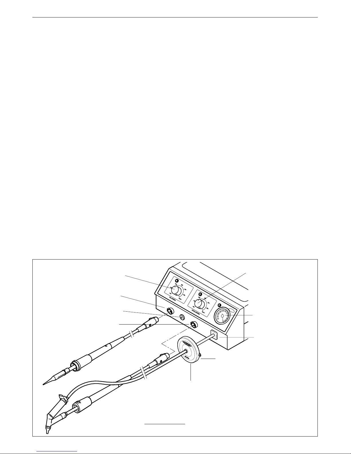
Spare filters
Ref.0781046
External desoldering air filter
Ref.0781184
% Vacuum indicator
and obstruction degree
in the suction circuit
Desoldering
temperature selection
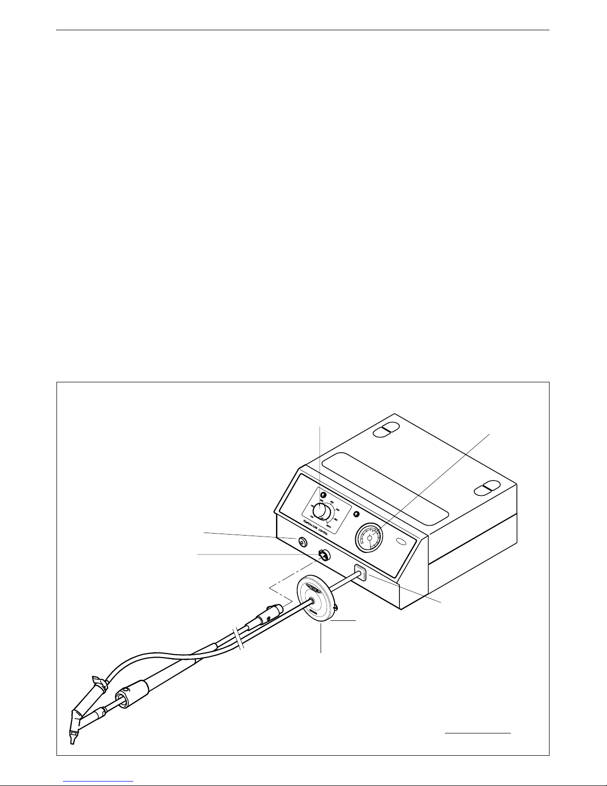
The desoldering iron is connected to the station following the below procedure:
The cable connection of the desoldering iron is connected to the desoldering connector of
the station and the vacuum hose is connected to the external desoldering air filter, which is
connected to the vacuum connection of the station.
Very important, it is essential to connect
the mentioned filter to prevent from damaging the vacuum pump.
Soldering
temperature selection
Aspiration inlet
Desoldering connector
Soldering connector
Equipotential terminal
Page 4
2
Control Unit technical data
1. Station maximum power: 100W
2. Safety transformer with mains separator:
230V/24V 50Hz - 120V/24V 60Hz
3. Temperature range: from 100 till 400°C.
4. Programmed temperature accurate: ± 5%.
5. Green LED temperature adjustment optical
control.
6. Abides the CE standards for electrical
security, electromagnetical compatibility and
antistatic protection.
7. Equipotential connector and the tool tip are
connected to station mains ground supply for
ESD protection.
Temperature adjustment for special tips
The temperatures on the dial are set for the
75W desoldering iron of with tip 20 DE, which
is included in the equipment. A change of tip or
soldering iron model could involve a variation of
± 7% in the set temperature.
ENGLISH
FEATURES
Station composition
TA 5120 EU: Ref. 5120200
TA 5120 UK: Ref. 5120201
TA 5120 USA: Ref. 5120100
- Analog Control Unit 230V Ref. 5230200
- Analog Control Unit 120V Ref. 5230100
- Desoldering iron 75W Ref. 3040000
- Desold. iron stand UD 1500 Ref. 0290150
- External desoldering air filter Ref. 0781184
- Set of tools and
replacement filters Ref. 0781181
- Tip removal device Ref. 0114108
- Instructions manual Ref. 0965405
Weight of packaged equipment: 3,6 kg
Besides the desoldering iron supplied with this
station, the Control Unit will also take the 20W
Ref. 3000000, 50W Ref. 3010000, 60W
Ref. 3020000 with solder feed and 70W
Ref. 3070000 soldering irons.
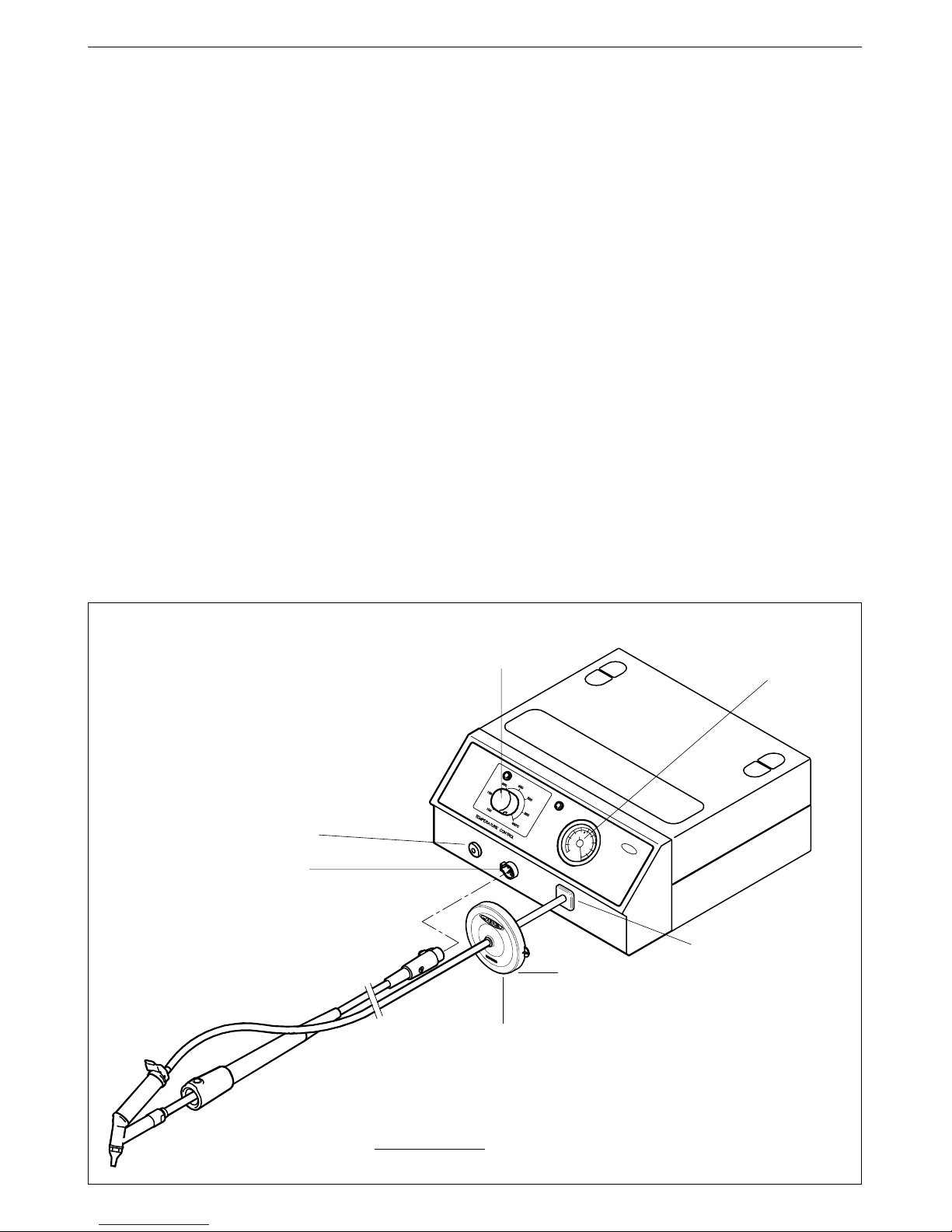
Desoldering connector
Equipotential terminal
Spare filters
Ref.0781046
External desoldering air filter
Ref.0781184
% Vacuum indicator
and obstruction degree
in the suction circuit
Desoldering
temperature selection
The desoldering iron is connected to the station following the below procedure:
The cable connection of the desoldering iron is connected to the desoldering connector
of the station and the vacuum hose is connected to the external desoldering air filter,
which is connected to the vacuum connection of the station.
Very important, it is
essential to connect the mentioned filter to prevent from damaging the vacuum pump.
Aspiration inlet
Page 5
3
1
23
ENGLISH
RECOMMENDATIONS FOR USE
For soldering and desoldering
- Clean the contacts to be desoldered of dust
or dirt.
- Preferably select a temperature below 375°C.
Excess temperature may cause the printed
circuit tracks to break loose.
- The tip must be well tinned for good heat
conduction. If it has been inoperative for any
length of time, it should be retinned.
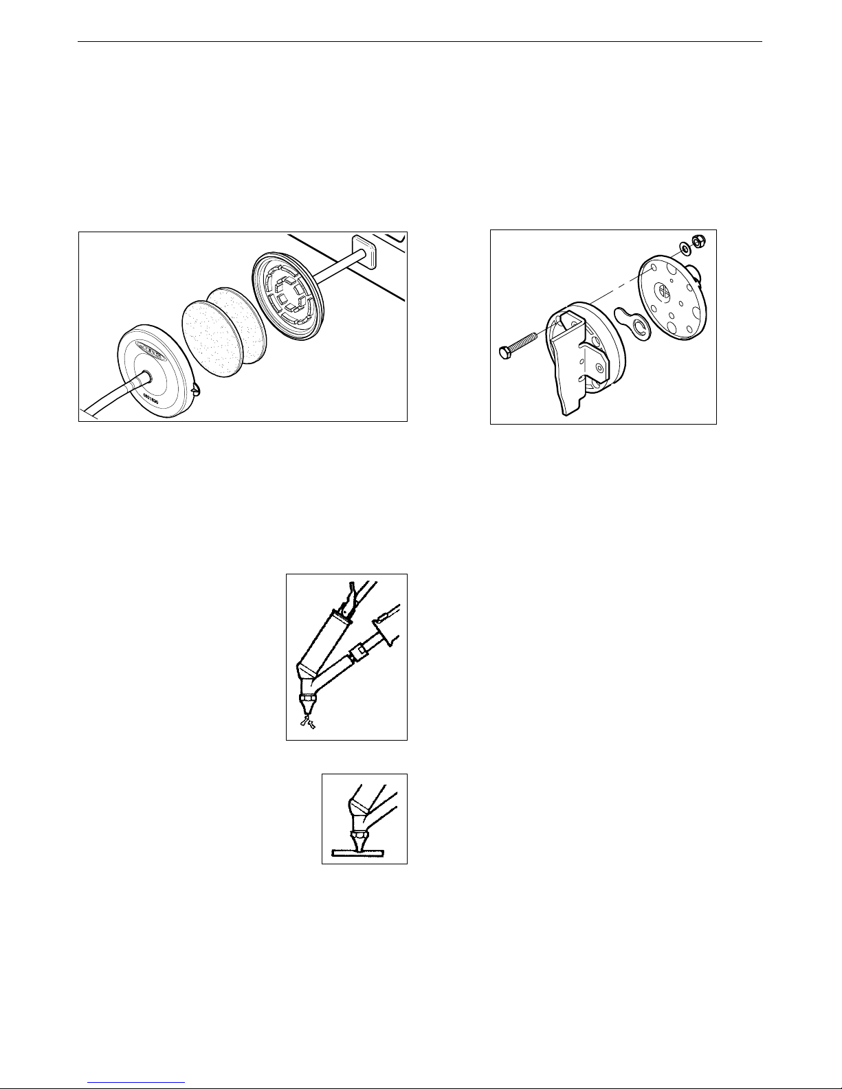
Desoldering process
Use the tip model with a larger diameter than
the pad to be desoldered, so as to achieve
maximum aspiration and thermal efficiency.
1 Apply the desoldering iron tip so that the
component terminal penetrates within its
orifice.
2 When the solder liquefies, start gently to rotate
the desoldering tip so that the component’s
terminal can be eased away from the sides.
3 Press then, not before, the vacuum pump
push-button just long enough to aspirate the
solder.
After pressing the desoldering key there is a
slight delay until the self-contained vacuum
pump stops, this is to make sure that the
vacuum circuit is completely empty.
If any solder remains are left on any terminal
after attempting to desolder it, resolder it with
fresh solder and repeat the desoldering operation.
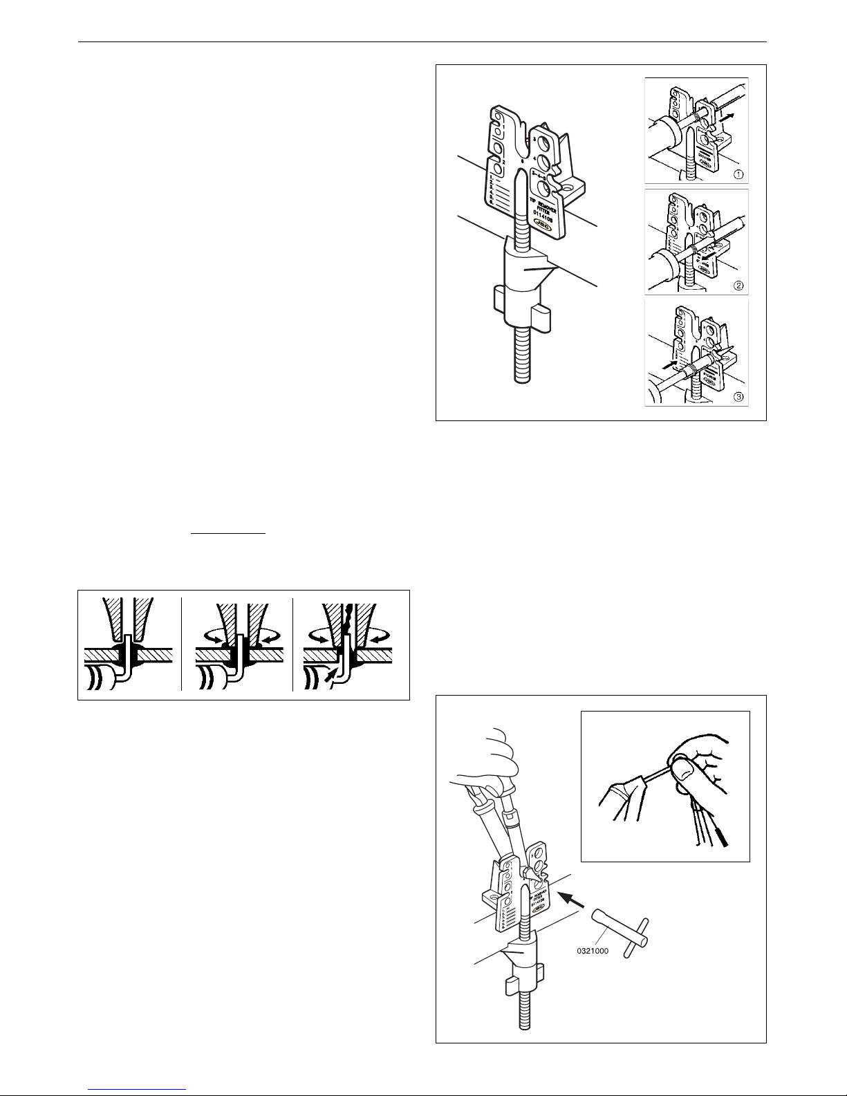
Soldering iron tip replacement
Use the tip removal device Ref. 0114108.
➀
Remove the ring to release the tip.
➁
Remove the tip by pulling the soldering iron
lengthwise, without forcing the element.
➂
Insert the new tip and make sure that it has
penetrated fully home.
a
b
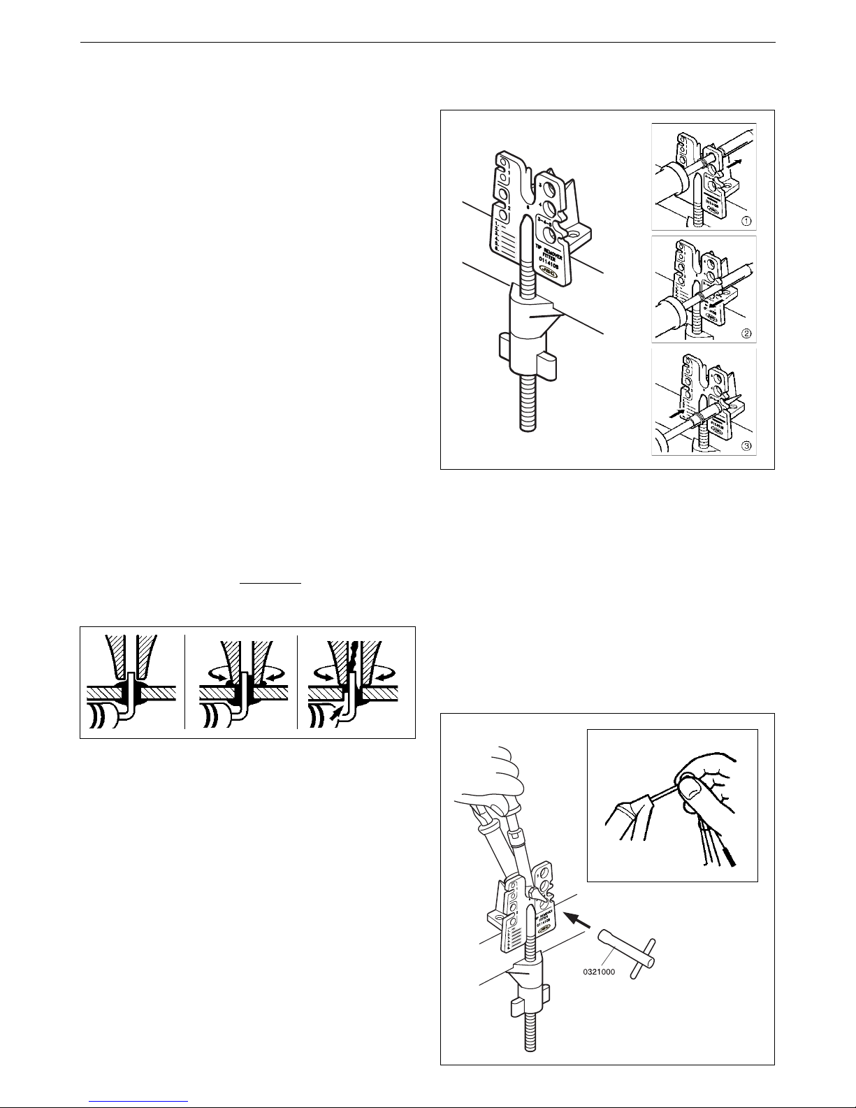
Desoldering iron tip replacement
This operation should be done while the tip is
hot, at a minimum temperature of 250°C, so
that any tin left inside is in molten state.
- Rest the desoldering iron body in the tip
removal device and unscrew the tip to be
replaced, with the aid of the spanner
supplied (Fig. a).
- Insert the thickest rod inside the desoldering
iron body duct (Fig. b).
Page 6
4
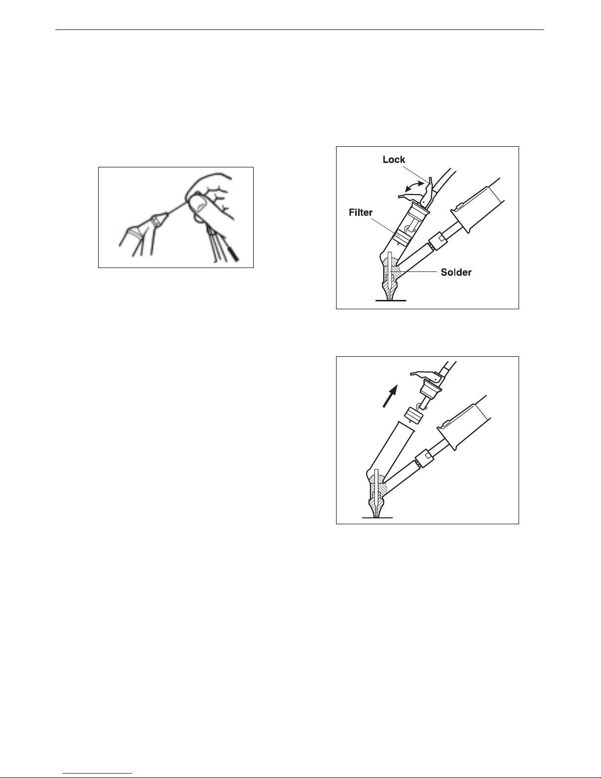
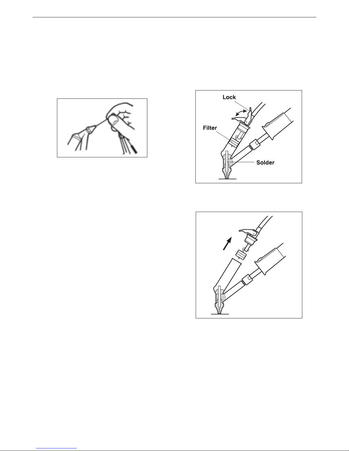
Emptying the desoldering tank and changing
the filter
This should be done while the tip is still hot,
with a minimal temperature of 250°C, to make
sure the tin is melted, and therefore every
precaution should be taken.
- Release the clasp of the lock.
ENGLISH
- Fit the new tip, and tighten up with the
spanner until the aluminium gasket is
compressed to achieve a good air tightness.
Tip care
- The largest rod that fits in the tip hole should
periodically be passed through in order to
clean the intake tube.
- To clean the tips, use the sponge included
with the stand and check it is slightly
moisted.
Only deionised water (car batterOnly deionised water (car batter
Only deionised water (car batterOnly deionised water (car batter
Only deionised water (car batter
y water)y water)
y water)y water)
y water)
should be used in orshould be used in or
should be used in orshould be used in or
should be used in or
der to wet the spongeder to wet the sponge
der to wet the spongeder to wet the sponge
der to wet the sponge.
If normal water was to be used, it is very likely
that the tip will become dirty due to the salts
dissolved within the water.
- Do not file the tips or use abrasive tools
which may damage the tip’s protective
surface coating and avoid knocking them
about.
- If the tip has been a long time without
being tinned, use the metal brush Ref.
0297705 adaptable to the support, to remove
any dirt and oxid.
IMPORTANT
::
::
: DO NOT press the pushbutton
vacuum pump while tinning the desoldering
tip, as the fumes given off by the flux would
quickly soil the ducts and filter of the air
circuit.
- Empty the tank by tipping up the soldering
iron.
- Insert through the tip hole the rod which
matches its diameter.
- Note the state of the filter and replace it if
soiled or damaged.
- Put the lock with the filter again and make
the clasp secure.
- Pull the lock then you take out the filter,
without spilling any of the solder in the
tank.
Page 7
5
- Press the vacuum pump start button.
The vacuum indicator should run into the red
zone (60% and 80% vacuum). If not, this means
air is getting in somewhere, either through the
desoldering tip, the tank stopper, or the pump
inlet filter stopper, or because the air pump does
not function correctly due to dirty valves which
occurs when the air filter has not been used
correctly.
ENGLISH
JBC reserves the right to change specifications mentioned
in this instructions manual without prior notice.
The suction indicator
should not go beyond the
green zone. If it runs into
the red zone, this will mean
that the suction circuit is
obstructed in some way
and the tip needs
unclogging or the filters
replacing.
To detect air leaks in the
circuit:
- Obstruct the tip inlet orifice
by pressing down on a
silicone disc, or bend the
tube connecting the
desoldering iron to the
filter.
Checking the suction circuit
To determinate if there is obstruction in the
suction circuit:
- Press the vacuum pump start button, with
the desoldering iron at a temperature of
not less than 250°C to keep the tin solder
melted.
Changing the pump inlet filter
Verify the filter at the entrance of the pump,
and change it if dirty or obstructed, therefor:
Open the filter pulling the flap.
Take out the 2 cotton filters, throw away those
which are soiled and replace them with new
ones. Always use 2 filters.
Close the filter and check the airtightness.
Cleaning the vacuum pump valve
Open the control unit as follow:
- Disconnect and open the control unit.
- Turn it upside down, remove the four rubber
feet and take out the four inner screws.
- Return the station to its normal position and
lift up the lid by getting hold of the sides.
- Undo the four screws fastening the pump cover.
- Clean the valve with a cloth dampened in
alcohol. If it is too soiled, replace it with
new one. Ref. 0982970.
Page 8
Agradecemos la confianza depositada en JBC al adquirir esta estación. Ha sido
fabricada con las más estrictas normas de calidad, para prestarle el mejor servicio.
Antes de poner en marcha el aparato, recomendamos leer con atención las
instrucciones que a continuación se detallan.
ESPAÑOL
CARACTERISTICAS
Composición de las estaciones
RA 5150 EU: Ref. 5150200
RA 5150 UK: Ref. 5150201
RA 5150 USA: Ref. 5150100
- Unidad de Control 230V Ref. 5330200
- Unidad de Control 120V Ref. 5330100
- Desoldador 75W Ref. 3040000
- Soldador 50W Ref. 3010000
- Soporte soldador US 1000 Ref. 0290100
- Soporte desoldador UD 1500 Ref. 0290150
- Conjunto filtro aspiración Ref. 0781184
- Juego de herramientas
y recambios de filtro Ref. 0781181
- Extractor de puntas Ref. 0114108
- Manual de instrucciones Ref. 0965405
Peso del equipo envasado: 3,8 kg
Además del soldador y desoldador que equipa
la estación, también se le pueden conectar
cualquiera de los soldadores de 20W Ref.
3000000, 60W Ref. 3020000 con aportación de
estaño y 70W Ref. 3070000.
Datos técnicos de la Unidad de Control
1. Potencia máxima: 175W
2. Transformador de seguridad separador de la
red: 230V/24V 50Hz - 120V/24V 60Hz
3. Selección analógica de la temperatura:
de 100 a 400°C.
4. Precisión de la temperatura programada: ± 5%
5. Control óptico de regulación de temperatura
por led verde.
6. Cumple la normativa CE sobre seguridad
eléctrica, compatibilidad electromagnética y
protección antiestática.
7. El borne equipotencial y la punta del soldador
están en conexión directa a la toma de tierra de
red para protección ESD.
Ajuste de temperatura
Las temperaturas que figuran en el dial, están ajustadas para el desoldador de 75W con la punta 20 DE
y el soldador de 50W con la punta R-10 D que se
suministran de origen con el equipo. El cambio de
modelo de punta o de soldador puede comportar
una variación de ±7% de la temperatura.
Filtros de recambio
Ref.0781046
Conjunto filtro aspiración
Ref.0781184
Vacuómetro
Indicador % de vacío
y grado de obstrucción
del circuito de aspiración
Selección temperatura
desoldador
El desoldador se conecta a la estación de la siguiente forma:
El cable del desoldador se debe conectar al conector desoldador de la estación y el
tubo de aspiración al CONJUNTO FILTRO ASPIRACION y este a la toma de aspiración
de la estación.
Muy importante, es indispensable intercalar el CONJUNTO FILTRO
ASPIRACION de lo contrario se inutilizará la bomba de aspiración.
Selección temperatura
soldador
Toma de aspiración
Conector desoldador
Conector soldador
Conector equipotencial
6
Page 9
CARACTERISTICAS
Composición de las estaciones
TA 5120 EU: Ref. 5120200
TA 5120 UK: Ref. 5120201
TA 5120 USA: Ref. 5120100
- Unidad de Control 230V Ref. 5330200
- Unidad de Control 120V Ref. 5330100
- Desoldador 75W Ref. 3040000
- Soporte desoldador UD 1500 Ref. 0290150
- Conjunto filtro aspiración Ref. 0781184
- Juego de herramientas
y recambios de filtro Ref. 0781181
- Extractor de puntas Ref. 0114108
- Manual de instrucciones Ref. 0965405
Peso del equipo envasado: 3,6 kg
Además del desoldador que equipa la estación,
también se le pueden conectar cualquiera de
los soldadores de 20W Ref. 3000000, 50W
Ref. 3010000, 60W Ref. 3020000 con aportación
de estaño y 70W Ref. 3070000.
ESPAÑOL
Datos técnicos de la Unidad de Control
1. Potencia máxima: 100W
2. Transformador de seguridad separador de la
red: 230V/24V 50Hz - 120V/24V 60Hz
3. Selección analógica de la temperatura:
de 100 a 400°C.
4. Precisión de la temperatura programada: ± 5%
5. Control óptico de regulación de temperatura
por led verde.
6. Cumple la normativa CE sobre seguridad
eléctrica, compatibilidad electromagnética y
protección antiestática.
7. El borne equipotencial y la punta del soldador
están en conexión directa a la toma de tierra de
red para protección ESD.
Ajuste de temperatura
Las temperaturas que figuran en el dial, están
ajustadas para el desoldador de 75W con la
punta 20 DE que se suministra de origen con
el equipo. El cambio de modelo de punta
puede comportar una variación de ± 7% de la
temperatura.
Filtros de recambio
Ref.0781046
Conjunto filtro aspiración
Ref.0781184
Vacuómetro
Indicador % de vacío
y grado de obstrucción
del circuito de aspiración
Selección temperatura
desoldador
El desoldador se conecta a la estación de la siguiente forma:
El cable del desoldador se debe conectar al conector desoldador de la estación y el
tubo de aspiración al CONJUNTO FILTRO ASPIRACION y este a la toma de aspiración
de la estación.
Muy importante, es indispensable intercalar el CONJUNTO FILTRO
ASPIRACION de lo contrario se inutilizará la bomba de aspiración.
Toma de aspiración
Conector desoldador
Conector equipotencial
7
Page 10
1 2
3
ESPAÑOL
a
b
Cambio de punta del desoldador
Esta operación debe realizarse en caliente a
una temperatura mínima de 250°C, para que
los residuos de estaño que hayan quedado en
el interior estén fundidos.
- Apoye el cuerpo del desoldador en el
extractor de puntas y desenrosque la punta
a sustituir, con la ayuda de la llave que se
suministra (Fig. a).
- Pase la baqueta más gruesa por el interior del
conducto del cuerpo desoldador (Fig. b).
➂
Introduzca la nueva punta y asegúrese de
que ha penetrado a fondo.
RECOMENDACIONES DE USO
Para soldar y desoldar
- Los componentes y el circuito deben estar
limpios y desengrasados.
- Con preferencia seleccione una temperatura
inferior a 375°C. El exceso de temperatura
puede provocar el desprendimiento de las
pistas del circuito impreso.
- La punta debe estar bien estañada para
conducir bien el calor. Si permanece mucho
tiempo en reposo, estáñela de nuevo.
Proceso para desoldar
Utilice un modelo de punta de mayor diámetro
interior que el pin a desoldar, con el fin de
conseguir el máximo de aspiración y de
transmisión térmica.
1 Apoye la punta del desoldador, de forma
que el terminal del componente penetre
dentro del orificio de la punta.
2 Cuando la soldadura se licúe, imprima a la
punta del desoldador un movimiento de
rotación que permita desprender de los
laterales el terminal del componente.
3 Accione entonces, no antes, el pulsador de
la bomba de vacío el tiempo necesario para
succionar la soldadura.
Cambio de punta del soldador
Utilice el extractor de puntas Ref. 0114108.
➀
Retire la anilla para liberar la punta.
➁
Extraiga la punta tirando del soldador, en
sentido longitudinal y sin forzar la resistencia.
Después de cada pulsación del botón del
desoldador hay un breve retardo hasta el paro
de la bomba de aspiración, con la finalidad de
asegurar que se vacía completamente el
circuito de aspiración.
Si algún terminal ha quedado con restos de
soldadura, después de intentar desoldarlo,
suéldelo nuevamente aportando estaño y repita
la operación de desoldar.
8
Page 11
ESPAÑOL
- Coloque la nueva punta. Apriete con la
llave hasta provocar el prensado de la junta
de aluminio para conseguir una buena
estanqueidad.
Conservación de las puntas
- Periódicamente se debe pasar la baqueta del
diámetro mayor que permita el agujero de la
punta, para limpiar el conducto de aspiración.
- Para la limpieza de las puntas utilice la
esponja del soporte, que debe estar húmeda
pero no empapada de agua.
Es necesario utilizar sólo aguaEs necesario utilizar sólo agua
Es necesario utilizar sólo aguaEs necesario utilizar sólo agua
Es necesario utilizar sólo agua
desionizada para humedecer la esponja.desionizada para humedecer la esponja.
desionizada para humedecer la esponja.desionizada para humedecer la esponja.
desionizada para humedecer la esponja.
Si utiliza agua normal es muy probable que
la punta se ensucie con las sales disueltas
que hay en el agua.
- No lime ni utilice herramientas abrasivas
que puedan destruir la capa de protección
superficial de la punta y evite los golpes.
- Si la punta ha estado mucho tiempo sin
ser estañada, utilice el cepillo metálico
Ref. 0297705 adaptable al soporte, para
eliminar el óxido y la suciedad.
IMPORTANTE: NO hacer funcionar la bomba
de vacío durante la operación de estañado de
la punta del desoldador, ya que el humo que
desprende el flux ensuciará rápidamente los
conductos y el filtro de entrada de la bomba.
Vaciado depósito del desoldador y cambio
de filtro
Esta operación debe realizarse en caliente, a
una temperatura mínima de 250°C para que el
residuo de estaño que contiene el depósito
esté fundido, por lo que debe hacerse con
cuidado para evitar quemaduras.
- Libere el cierre del tapón (Lock)
- Tire del tapón y con ello extraerá el filtro,
sin derramar la soldadura (Solder) contenida
en el depósito.
- Vacíe el depósito inclinando el soldador.
- Introduzca por el orificio de la punta la
baqueta correspondiente a su diámetro.
- Observe el estado del filtro (Filter) y
cámbielo si estuviera sucio o degradado.
- Vuelva a poner el tapón con el filtro y
asegure el cierre.
9
Page 12

JBC se reserva el derecho de introducir modificacionesJBC se reserva el derecho de introducir modificaciones
JBC se reserva el derecho de introducir modificacionesJBC se reserva el derecho de introducir modificaciones
JBC se reserva el derecho de introducir modificaciones
técnicas sin previo aviso.técnicas sin previo aviso.
técnicas sin previo aviso.técnicas sin previo aviso.
técnicas sin previo aviso.
- Obstruya el orificio de
entrada de la punta,
presionando sobre un disco
de silicona, o estrangule el
tubo que va del desoldador
al filtro.
- Pulse el botón de puesta en marcha de la
bomba de vacío.
El indicador del vacuómetro deberá alcanzar la
zona roja, entre 60 y 80 % de vacío. Si no es así,
significa que hay una entrada de aire por
cualquiera de las juntas, como pueden ser la
El indicador del vacuómetro
no deberá superar la zona
verde. Si alcanza la zona
roja, indicará que existe
obstrucción en el circuito de
aspiración, por lo que
deberá desatascar la punta
pasando la baqueta
correspondiente y/o
sustituyendo los filtros de
algodón y de fibra.
Para detectar pérdidas de
aspiración en el circuito:
Cambio del filtro de entrada de la bomba
Compruebe el filtro de entrada de la bomba y
cambielo si está sucio u obturado, para ello:
- Abra el filtro tirando de las lengüetas.
- Extraiga los 2 filtros de algodón, deseche los
que estuvieran sucios y coloque unos nuevos
en su lugar. Use siempre 2 filtros.
Cierre el filtro y verifique que no hayan perdidas
de aspiración.
Comprobación del circuito de aspiración
Para determinar si existe obstrucción en el
circuito de aspiración:
- Pulse el botón de puesta en marcha de la
bomba de vacío, con el desoldador a una
temperatura no inferior a 250°C para
mantener fundido el estaño.
Limpieza de la válvula interna de la bomba de
vacío
Debe abrir la unidad de control, para ello:
- Desconecte la estación de la red eléctrica.
- Invierta la unidad, quite las cuatro patas
de goma y saque los cuatro tornillos
interiores.
- Ponga la estación en posición normal y
levante la tapa superior.
- Desenrosque los cuatro tornillos que sujetan
la tapa de la bomba.
punta del desoldador, el tapón de cierre del
depósito, el tapón del filtro de entrada de la
bomba, o bien la bomba no aspira suficiente
por estar sucia la válvula interna motivado por
haber trabajado sin el conjunto filtro aspiración o
sin filtros.
- Limpie la válvula con un paño mojado
en alcohol. Si estuviera excesivamente
impregnada, cámbiela por una nueva.
Ref. 0982970.
10
ESPAÑOL
Page 13

11
JBC garantit cet appareil contre tout défaut de fabrication, dans les conditions qui sont
reprises sur la feuille de garantie annexée. Nous vous rappelons que vous perdez la
garantie si la station a été manipulée. Avant de mettre l’appareil en marche, nous vous
conseillons de lire attentivement les instructions qui sont détaillées ci-dessous.
FRANÇAIS
CARACTERISTIQUES
Composition de la station
RA 5150 EU: Réf. 5150200
RA 5150 UK: Réf. 5150201
RA 5150 USA: Réf. 5150100
- Unité de Contrôle 230V Réf. 5330200
- Unité de Contrôle 120V Réf. 5330100
- Fer à dessouder 75W Réf. 3040000
- Fer à souder 50W Réf. 3010000
- Support souder US 1000 Réf. 0290100
- Support dessouder UD 1500 Réf. 0290150
- Ensemble filtre aspiration Réf. 0781184
- Jeu d’outils et pièces
de rechange de filtre Réf. 0781181
- Extracteur de pannes Réf. 0114108
- Manuel d’instructions Réf. 0965405
Poids de l’équipement emballé : 3,8 kg
En plus du fer à souder et fer à dessouder
dont la station est équipée, on peut connecter
également n'importe quel des fers à souder
20W Réf. 3000000, 60W Réf. 3020000 avec
apport d'étain et 70W Réf. 3070000.
Données techniques de l'Unité de Contrôle
1. Puissance max. de la station: 175W
2. Transformateur de sécurité séparateur du réseau:
230V/24V 50Hz - 120V/24V 60Hz
3. Sélection de température entre: 100 et 400°C.
4. Précision température programmée: + 5%
5. Contrôle optique de régulation de
température par led vert.
6. Elle est conforme aux normes CE pour la
sécurité électrique, la compatibilité
électromagnétique et la protection antistatique.
7. La prise équipotentielle et la cartouche sont
en connexion directe avec la prise de terre
secteur pour la protection antistatique (ESD).
Réglage de la température
Les températures sur le dial sont adaptées au fer
à dessouder 75W avec panne 20 DE et au fer à
souder 50W avec panne R-10 D, qui est inclure
dans l’équipement. Le changement de modèle de
panne ou de fer à souder peut comporter une
variation de la température de ± 7%.
Filtres de rechange
Réf.0781046
Ensemble filtre aspiration
Réf.0781184
Vacuomètre
indicateur de % de vide
et graduation
de la obstruction
du circuit d'aspiration
Sélection de la température
fer à dessouder
Le fer à dessouder se connecte à la station de la façon suivante:
Le câble du fer à dessouder doit être connecté au connecteur fer à dessouder de la
station et le tube d’aspiration à l’ENSEMBLE FILTRE ASPIRATION, et ce dernier à la
prise d’aspiration de la station.
Très important, il est indispensable d’intercaler
l’ENSEMBLE FILTRE ASPIRATION sinon on rendra inutilisable la pompe d’aspiration.
Sélection de la température
fer à souder
Prise d'aspiration
Connecteur fer à dessouder
Connecteur fer à souder
Connecteur équipotentiel
Page 14

CARACTERISTIQUES
Composition de la station
TA 5120 EU: Réf. 5120200
TA 5120 UK: Réf. 5120201
TA 5120 USA: Réf. 5120100
- Unité de Contrôle 230V Réf. 5230200
- Unité de Contrôle 120V Réf. 5230100
- Fer à dessouder 75W Réf. 3040000
- Support dessouder UD 1500 Réf. 0290150
- Ensemble filtre aspiration Réf. 0781184
- Jeu d’outils et pièces
de rechange de filtre Réf. 0781181
- Extracteur de pannes Réf. 0114108
- Manuel d’instructions Réf. 0965405
Poids de l’équipement emballé : 3,6 kg
En plus du fer à dessouder dont la station est
équipée, on peut connecter également n'importe
quel des fers à souder 20W Réf. 3000000, 50W
Réf. 3010000, 60W Réf. 3020000 avec apport
d'étain et 70W Réf. 3070000.
FRANÇAIS
Données techniques de l'Unité de Contrôle
1. Puissance max. de la station: 100W
2. Transformateur de sécurité séparateur du réseau:
230V/24V 50Hz - 120V/24V 60Hz
3. Sélection de température entre: 100 et 400°C.
4. Précision température programmée: + 5%
5. Contrôle optique de régulation de
température par led vert.
6. Elle est conforme aux normes CE pour la
sécurité électrique, la compatibilité
électromagnétique et la protection antistatique.
7. La prise équipotentielle et la cartouche sont
en connexion directe avec la prise de terre
secteur pour la protection antistatique (ESD).
Réglage de la température
Les températures sur le dial sont adaptées
au fer à dessouder 75W avec panne 20 DE
qui est inclure dans l’équipement. Le
changement de modèle de panne ou de fer
à souder peut comporter une variation de la
température de ± 7%.
Filtres de rechange
Réf.0781046
Ensemble filtre aspiration
Réf.0781184
Vacuomètre
indicateur de % de vide
et graduation
de la obstruction
du circuit d'aspiration
Sélection de la température
fer à dessouder
Le fer à dessouder se connecte à la station de la façon suivante:
Le câble du fer à dessouder doit être connecté au connecteur fer à dessouder de la
station et le tube d’aspiration à l’ENSEMBLE FILTRE ASPIRATION, et ce dernier à la
prise d’aspiration de la station. Très important, il est indispensable d’intercaler
l’ENSEMBLE FILTRE ASPIRATION sinon on rendra inutilisable la pompe d’aspiration.
Prise d'aspiration
Connecteur fer à dessouder
Connecteur équipotentiel
12
Page 15

13
FRANÇAIS
a
b
1 2
3
Changement de la panne du fer à dessouder
Cette opération doit être réalisée à chaud à une
température minimale de 250°C, pour que les
résidus d’étain qui seraient restés à l’intérieur
soient fondus.
- Appuyez le corps du fer à dessouder sur
l’extracteur de pannes et dévissez la panne
à remplacer, au moyen de la clef qui est
fournie (Fig. a).
- Passez la baguette plus épaisse par l’intérieur
du conduit du corps du fer à dessouder (Fig. b).
➂
Introduire la nouvelle panne et assurez-vous
que elle ait pénétré jusqu’au fond.
RECOMMANDATIONS D’UTILISATION
Pour souder et dessouder
- Les composants et le circuit doivent être
propres et dégraissés.
- De préférence choisir une température
inférieure à 375°C. L’excès de température
peut provoquer le décollement des pistes du
circuit imprimé.
- La panne doit être bien étamée pour bien
conduire la chaleur. Lorsqu’elle est restée
longtemps au repos, l’étamer à nouveau.
Procédé de dessoudure
Utiliser un modèle de panne de plus grand
diamètre que le pad à dessouder, dans le but
d’obtenir le maximum d’aspiration et de
rendement thermique.
1 Appuyer la panne du fer à dessouder, de
façon que l’extrémité du composant pénètre
dans l’orifice de la panne.
2 Lorsque la soudure se liquéfie, imprimer à
la panne du fer à dessouder un mouvement
rotatif qui permet de détacher des extrémités
de la patte du composant.
3 Appuyer à ce moment-là, et non pas avant,
sur le bouton de commande de la pompe à
vide le temps nécessaire pour aspirer par
succion la soudure.
Après avoir appuyé sur le bouton du fer à
dessouder il y a un bref retard jusqu` à l’arrêt de
la pompe d’aspiration, dans le but de s’assurer
que le circuit d’aspiration soit complètement
vide.
Si une borne a gardé des restes de soudure
après que l’on a essayé de la dessouder, la
souder à nouveau en faisant un apport d”étain
et répéter l’opération de dessoudage.
Changement de la panne du fer à souder
Utilisez l’extracteur de pannes. Réf. 0114108.
➀
Retirez l’anneau pour libérer la panne.
➁
Extraire la panne en tirant légèrement le fer à
souder, afin de ne pas endommager la
résistance.
Page 16

14
FRANÇAIS
Conservation des pannes
- Nettoyer périodiquement le circuit d’aspiration,
en introduisant la baguette de plus grand
diamètre dans l’orifice de l’embout.
- Placez la nouvelle panne, vissez avec la
clef jusqu’à presser le joint d’aluminium, en
obtenant ainsi une bonne étanchéité.
- Pour le nettoyage des buses veuillez utiliser
l’éponge du support, qui doit être légèrement
humide.
Il est nécessairIl est nécessair
Il est nécessairIl est nécessair
Il est nécessair
e d’utiliser de l’eaue d’utiliser de l’eau
e d’utiliser de l’eaue d’utiliser de l’eau
e d’utiliser de l’eau
deionisée pour humidifier l’épongedeionisée pour humidifier l’éponge
deionisée pour humidifier l’épongedeionisée pour humidifier l’éponge
deionisée pour humidifier l’éponge
..
..
. Si vous
utilisez de l’eau courante, il est très probable
que la panne soit contaminée par les sels
dissous contenus dans l’eau.
- Ne limez ni n’utilisez aucun outil abrasif
qui pourrait détruire la couche de
protection superficielle de la panne et
evitez les coups.
- Si la panne n'a pas été étamée depuis
longtemps, nettoyez-la à l'aide de la brosse
métallique Réf. 0297705.
IMPORTANT: NE PAS faire fonctionner la
pompe à vide pendant l’opération d’étamage
de la panne du fer à dessouder, étant donné
que la fumée qui dégage le flux, encrasserait
rapidement les conduits et le filtre du circuit
pneumatique.
Vidange réservoir du fer à dessouder et
remplacement du filtre
Cette opération doit être réalisée à chaud, avec
une température minimal de 250°C, pour que la
soudure soit fondue, car cela doit être fait avec
le maximum de soin.
- Libérez la fermeture du bouchon (Lock).
- Tirez le bouchon. En faisant cette opération,
vous extrairez le filtre, sans derramer la
soudure (Solder) contenue dans le réservoir.
- Videz le réservoir en inclinant le fer à dessouder.
- Introduisez par l’orifice de la panne la
baguette correspondant à son diamètre.
- Regardez l’état du filtre et changez-le s’il
est encrassé ou dégradé.
- Remettre le bouchon avec le filtre et
assurez-vous de la fermeture.
Page 17

JBC se réserve le droit d’introduire des varations techniques
sans préavis.
L’indicateur d’aspiration ne
doit pas dépasser la zone
verte. S’il atteint la zone
rouge, cela signifie qu’il y
a une obstruction dans le
circuit aspirant. Il faudra
alors déboucher la panne
ou remplacer les filtres.
Pour détécter quelque perte
dans le circuit aspirant:
- Obstruez l’orifice d’entrée
de la panne, en pressant
sur un disque de silicone,
ou courbez le tuyau qui va
du fer à dessouder au filtre.
FRANÇAIS
Vérification du circuit aspirant
Pour détérminer s’il y a quelque obstruction dans
le circuit aspirant:
- Pressez le bouton de mise en marche de la
pompe à vide, le fer à dessouder étant à
une température non inférieure à 250°C
pour que la soudure reste fondue.
- Pressez le bouton de mise en route de la
pompe à vide.
L’indicateur d’aspiration doit atteindre la zone
rouge (60 el 80 % de vide). Si ce n’est pas le
cas, ce la signifie qu’il y a une entrée d’air par
l’un ou l’autre des joints comme la panne du fer
à dessouder, le bouchon de fermeture du
Nettoyage de la soupape de la pompe à vide
Pour ouvrir l’unité de contrôle:
- Débranchez la station du réseau électrique.
- Renversez-la, enlevez les quatre pieds en
caoutchouc et retirez les quatre vis intérieures.
- Mettez la station en position normale et levez
le couvercle supérieur en appuyant sur les
côtés.
- Desserrer les quatre pieds fixant le couvercle
de la pompe.
- Nettoyez la soupape avec un chiffon imbibé
d’alcool. Si elle est excessivement imprégnés,
remplacez-la par une nouveau Réf. 0982970.
Changement du filtre d'entrée de la pompe
Vérifiez le filtre d'entrée de la pompe et
changez-le s'il est sale ou obstrué, pour cela:
Ouvrir le filtre en tirant sur les languettes.
Extrayez les 2 filtres du coton, jetez ceux qui
sont sales et placez les nouveaux à leur place.
Utilisez toujours 2 filtres.
Fermez le filtre et vérifiez l'étanchéité.
réservoir, le bouchon du filtre d’entrée de la
pompe, ou alors que la pompe n’aspire pas
suffisamment car les clapets sont sales dû au
fait d’avoir travaillé sans l’ensemble filtre
aspiration ou sans filtres.
15
Page 18

Wir danken Ihnen für das JBC mit dem Kauf dieser Station erwiesene Vertrauen.
Er ist mit den strengsten Qualitätsmaßstäben hergestellt, so dass Sie optimale
Lötergebnisse erwarten dürfen. Vor Inbetriebnahme des Geräts lesen Sie bitte die
vorliegende Betriebsanleitung aufmerksam durch.
DEUTSCH
TECHNISCHE MERKMALE
Aufbau
RA 5150 EU: Ref. 5150200
RA 5150 UK: Ref. 5150201
RA 5150 USA: Ref. 5150100
- Steuereinheit 230V Ref. 5330200
- Steuereinheit 120V Ref. 5330100
- Entlötkolben 75W Ref. 3040000
- Lötkolben 50W Ref. 3010000
- Lötkolbenständer US 1000 Ref. 0290100
- Entlötkolbenständer UD 1500 Ref. 0290150
- Saugfiltereinheit Ref. 0781184
- Werkzeugsatz und
Ersatzfilter Ref. 0781181
- Spitzenabzieher Ref. 0114108
- Betriebsanleitungen Ref. 0965405
Gewicht des verpackten Geräts: 3,8 kg
Ausserdem Lötkolben und dem Entlötkolben
die mit der Station geliefert werden, können
auch die Lötkolben 20W Ref. 3000000, 60W mit
Zinnzufuhr Ref. 3020000 und 70W Ref. 3070000
angeschlossen werden.
Technische Angaben vom Steuereinheit
1. Maximale Leistung der Station: 175W
2. Sicherheitstransformator mit Netztrennung:
230V/24V 50Hz - 120V/24V 60Hz
3. Temperaturwahl: von 100 bis 400° C.
4. Genauigkeit der eingestellten
Arbeitstemperatur: ± 5%.
5. Optische Temperaturkontrolle durch grüne
LED-Anzeige.
6. Erfüllt die Sicherheitsvorschriften der CE über
elektrische Sicherheit, elektromagnetische
Kompatibilität und antistatischer Schutz.
7. Die Equipotentialausgleichsbuchse und die
Lötspitze sind zum Schutz gegen
elektrostatische Entladungen mit der Erdung
des Netzsteckers verbunden.
Temperatureinstellung
Die auf den Dial angegebenen Temperaturwerte
beziehen sich auf der Entlötkolben 75W mit Spitze
20 DE und der Lötkolben 50W mit Spitze R-10 D.
Beim Tauschen von Spitzen- und Lötkolbenmodelle
kann es zu ± 7% temperatur abweichungen
kommen.
Ersatzfilter
Ref.0781046
Saugfiltereinheit
Ref.0781184
Vakuummesser
% - Vakuum - und Anzeige
des Verstopfungsgrades
im Saugkreis
Entlötgerät
Anwahl Temp.
Der Entlötkolben wird folgendermaßen an die Station angeschlossen:
Das Anschlusskabel des Entlötkolbens wird in die Buchse des Entlötgerat
eingesteckt und der Vakuumschlauch in die Saugfiltereinheit, welche ihrerseits
an den Vakuumanschluss der Station angeschlossen wird.
Sehr wichtig: Es ist
unbedingt erforderlich die Saugfiltereinheit zwischenzuschalten, da ansonsten
die Vakuumpumpe beschädigt wird.
Lötgerat
Anwahl Temp.
Sauganschluss
Buchse Entlötgerat
Buchse Lötgerat
Potentialausgleichsbuchse
16
Page 19

DEUTSCH
Technische Angaben vom Steuereinheit
1. Maximale Leistung der Station: 100 W
2. Sicherheitstransformator mit Netztrennung:
230 V / 24 V 50 Hz - 120 V / 24 V 60 Hz
3. Temperaturwahl: von 100 bis 400° C.
4. Genauigkeit der eingestellten
Arbeitstemperatur: ± 5%.
5. Optische Temperaturkontrolle durch grüne
LED-Anzeige.
6. Erfüllt die Sicherheitsvorschriften der CE über
elektrische Sicherheit, elektromagnetische
Kompatibilität und antistatischer Schutz.
7. Die Equipotentialausgleichsbuchse und die
Lötspitze sind zum Schutz gegen
elektrostatische Entladungen mit der Erdung
des Netzsteckers verbunden.
Temperatureinstellung
Die auf den Dial angegebenen Temperaturwerte
beziehen sich auf der Entlötkolben 75W mit
Spitze 20 DE. Beim Tauschen von Spitzen- und
Lötkolbenmodelle kann es zu ± 7% temperatur
abweichungen kommen.
TECHNISCHE MERKMALE
Aufbau
TA 5120 EU: Ref. 5120200
TA 5120 UK: Ref. 5120201
TA 5120 USA: Ref. 5120100
- Steuereinheit 230 V Ref. 5230200
- Steuereinheit 230 V Ref. 5230200
- Entlötkolben 75 W Ref. 3040000
- Entlötkolbenständer UD 1500 Ref. 0290150
- Saugfiltereinheit Ref. 0781184
- Werkzeugsatz und
Ersatzfilter Ref. 0781181
- Spitzenabzieher Ref. 0114108
- Betriebsanleitungen Ref. 0965405
Gewicht des verpackten Geräts: 3,6 kg
Ausserdem Entlötkolben der mit der Station
geliefert wird, können auch die Lötkolben 20 W
Ref. 3000000, 50 W Ref. 3010000, 60 W mit
Zinnzufuhr Ref. 3020000 und 70 W Ref. 3070000
angeschlossen.
Ersatzfilter
Ref.0781046
Saugfiltereinheit
Ref.0781184
Vakuummesser
% - Vakuum - und Anzeige
des Verstopfungsgrades
im Saugkreis
Entlötgerät
Anwahl Temp.
Sauganschluss
Buchse Entlötgerat
Potentialausgleichsbuchse
Der Entlötkolben wird folgendermaßen an die Station angeschlossen:
Das Anschlusskabel des Entlötkolbens wird in die Buchse des Entlötgerat
eingesteckt und der Vakuumschlauch in die Saugfiltereinheit, welche ihrerseits
an den Vakuumanschluss der Station angeschlossen wird.
Sehr wichtig: Es ist
unbedingt erforderlich die Saugfiltereinheit zwischenzuschalten, da ansonsten
die Vakuumpumpe beschädigt wird.
17
Page 20

DEUTSCH
EMPFEHLUNGEN FÜR DEN GEBRAUCH
Zum Löten und Entlöten
- Komponenten und Leiterplatte müssen
sauber und entfettet sein.
- Möglichst immer mit Temperaturen unter
375° C arbeiten. Höhere Temperaturen
können ein Ablösen der Leitungsbahnen zur
Folge haben.
- Wurde der Entlötkolben während einer
längeren Zeit nicht gebraucht, ist er erneut
zu verzinnen.
Entlöten
Um eine maximale Saug- und Wärmeleistung
sicherzustellen, sollte der Durchmesser der
Entlötspitze stets größer als das zu bearbeitende
Pad sein.
1 Entlötkolben so aufsetzen, daß der Pin des
jeweiligen Bauelements in die Kolbenöffnung
hineinragt.
2 Sobald sich das Lot verflüssigt, den
Entlötkolben drehen bzw. hin- und
herbewegen, so daß sich der Pin seitlich löst
und das darunterliegende Zinn abgesaugt
werden kann.
3 Druckschalter der Vakuumpumpe nur so lange
drücken, bis das vorhandene Lötzinn
abgesaugt ist.
a
b
1
23
Nach jedem drücken des Betriebsknofes des
Entlötkolbens ist ein kurzes warten erforderlich
bevor man die Saugpumpe abstellt, um sicher
zustellen das alle Saugleitungen komplet leer
sind.
Verbleiben an einem Pin nach dem Entlöten
Zinnrückstände, ist dieser durch neue Zinnzufuhr
wieder zu verlöten und erst danach ein zweites
Mal zu entlöten.
Spitzenwechsel Lötkolben
Hierzu Spitzenabzieher Ref. 0114108 verwenden.
➀
Lötspitze durch Abziehen des Rings lösen.
➁
Spitze durch Wegziehen des Lötkolbens
herausnehmen.
Spitzenwechsel Entlötkolben
Beim Entlötkolben muß der Spitzenwechsel bei
einer Temperatur von mindestens 250° C
erfolgen, damit sich die Zinnrückstände im
Inneren des Kolbens nicht verfestigen.
- Entlötkolben auf den Spitzenabzieher legen
und spitze mit dem mitgelieferten Schlüssel
herausschrauben (Abb. a).
- Dickere Nadel in die innere Leitung des
Entlötkolbens einführen (Abb. b).
➂
Ordnungsgemäßen Sitz der neuen Spitze
überprüfen.
18
Page 21

Entleerung des Auffangbehälters und
Filterwechsel
Dieser Vorgang muß mit größter Vorsicht bei
heißem Kolben erfolgen, bei einer Temperatur
von mindestens 250° C erfolgen, damit sich die
Zinnrückstände im Inneren des Kolbens nicht
verfestigen.
- Behälterverschluß (Lock) entsprechend der
nebenstehenden Abbildung lösen.
DEUTSCH
- Neue Spitze einsetzen und mit dem
Schlüssel anziehen, bis die
Aluminiumdichtung hermetisch schließt.
Behandlung der Spitzen
- Die Saugleitung ist in regelmäßigen
Abständen mit Hilfe des für die jeweilige
Spitze dicksten Reinigungsstäbchens von
etwaigen Rückständen zu befreien.
- Zur Reinigung der Spitzen ist der im
Kolbenständer vorgesehene Schwamm zu
benutzen, der leicht mit Wasser
angefeuchtet sein sollte.
Es ist erEs ist er
Es ist erEs ist er
Es ist er
forfor
forfor
for
derlich zum Befeuchten desderlich zum Befeuchten des
derlich zum Befeuchten desderlich zum Befeuchten des
derlich zum Befeuchten des
Schwamms nur entionisierSchwamms nur entionisier
Schwamms nur entionisierSchwamms nur entionisier
Schwamms nur entionisier
tes Wtes W
tes Wtes W
tes W
asser zuasser zu
asser zuasser zu
asser zu
verwendenverwenden
verwendenverwenden
verwenden. Wenn normales Wasser benutzt
wird, ist es sehr wahrscheinlich, dass die
Spitze durch die im Wasser gelösten Salze
verschmutzt wird.
- Keine Feilen oder sonstige die Schutzschicht
der Spitze beeinträchtigende Werkzeuge
verwenden und vor Schlägen schützen.
- Ist die Spitze längere Zeit nicht verzinnt worden,
mit der zum Kolbenständer passenden
Metallbürste Ref. 0297705 reinigen.
WICHTIG
::
::
: Beim Verzinnen der Entlötspitze darf
die Vakuumpumpe NICHT in Betrieb sein; der
vom Flux freigesetzte Rauch würde sonst die
Leitungen und den Filter des Pneumatikkreises
zu schnell verschmutzen.
- Behälterverschluß mit Filter herausnehmen,
ohne dabei das im Auffangbehälter
angesammelte Zinn (Solder) zu verschütten.
- Auffangbehälter durch Abkippen des
Kolbens entleeren.
- In die Spitzenöffnung die ihrem Durchmesser
entsprechende Nadel einführen.
- Filter überprüfen und bei Verschmutzung
bzw. Abnutzung ersetzen.
- Behälterverschluß mit Filter wieder einsetzen
und absichern.
19
Page 22

Die Anzeige der
Saugleistung darf nicht
über den grünen Bereich
hinausgehen. Erreicht sie
den roten Bereich, liegt
eine Verstopfung des
Saugkreises vor, was eine
Reinigung der Spitze bzw.
eine Erneuerung der Filter
erforderlich macht.
Für Bestimmung des Dichtigkeitsverlust im
Saugkreis:
- Saugöffnung der Spitze
mit einer Silikonscheibe
abdichten bzw.
Saugleitung zwischen
Entlötkolben und Filter
abknicken.
DEUTSCH
- Vakuumpumpe über den entsprechenden
Schalter in Betrieb nehmen.
Der Unterdruckmesser muß nun im roten Bereich
liegen (60 bis 80% Vakuum). Ist dies nicht der
Fall, liegt ein durch die Dichtungen, die
Entlötspitze, den Verschluß des Auffangbehälters,
Technische und konstruktive Änderungen bei dieser
Betriebsanleitungen sind vorbehalten.
Reinigung der Pumpenventile
Zum Öffnen der Steuereinheit:
- Rückwand abnehmen.
- Steuereinheit umdrehen, die vier
Gummifüsse entfernen und anschließend die
vier Halteschrauben herausdrehen.
- Steuereinheit wieder in normale Position
bringen und oberen Gehäuseteil abheben.
- Die vier Schrauben des Pumpendeckels
herausschrauben.
Überprüfung des Saugkreises
Für Bestimmung der Verstopfung im Saugkreis:
- Vakuumpumpe bei heißem Entlötkolben
(mindestens 250° C) in Betrieb nehmen.
Auswechseln des Pumpenfilters
Kontrollieren Sie die Filter beim Eingang der
Pumpe, und wechseln Sie diese bei
Verschmutzung oder Verstopfung aus. Dafür:
Öffnen Sie den Filter an den dafür vorgesehenen
Flügeln.
Die 2 Baumwollenfilter herausnehmen. Sind
diese unbrauchbar geworden, durch neue
ersetzen. Stets 2 Filter verwenden.
Verschliessen Sie den Filter und überprüfen Sie,
dass er hermetisch verschlossen ist.
den Deckel des Pumpenfilters oder durch
verschmutzte Pumpenventile hervorgerufener
Lufteintritt vor, wodurch sich eine unzureichende
Saugleistung ergibt, da das interne Ventil durch
das Arbeiten ohne die Saugfiltereinheit oder ohne
Filter verschmutzt worden ist.
- Mit einem in Alkohol getränkten Lappen
reinigen. Bei übermäßiger Verschmutzung
austauschen. Ref. 0982970.
20
Page 23

21
La ringraziamo per la fiducia riposta nella JBC con l’acquisto di questa stazione.
È stato fabbricato secondo le più rigide norme di qualità, per offrirle il servizio migliore.
Prima di accendere l’apparecchio, Le consigliamo di leggere attentamente le istruzioni
riportate qui di seguito.
ITALIANO
CARATTERISTICHE
Composizione della stazione
RA 5150 EU: Rif. 5150200
RA 5150 UK: Rif. 5150201
RA 5150 USA: Rif. 5150100
- Unità di Controllo 230V Rif. 5330200
- Unità di Controllo 120V Rif. 5330100
- Dissaldatore 75W Rif. 3040000
- Saldatore 50W Rif. 3010000
- Supporto saldatore US 1000 Rif. 0290100
- Supporto disaldatore UD 1500 Rif. 0290150
- Gruppo filtro aspirazione Rif. 0781184
- Set di utensili e
ricambi del filtro Rif. 0781181
- Estrattore di punte Rif. 0114108
- Manuale di istruzione Rif. 0965405
Peso della confezione stazione completa: 3,8 kg
Oltre al saldatore e al dissaldatore di cui è dotata
questa stazione, possono essere adattati all’Unità
di Controllo i saldatori da 20W, con Rif. 3000000,
60W con apporto di stagno, con Rif. 3020000 e
quello da 70W, con Rif. 3070000.
Dati tecnici dell’Unità di Controllo
1. Potenza massima della stazione: 175W
2. Trasformatore di sicurezza con isolamento
della rete: 230V/24V 50Hz - 120V/24V 60Hz
3. Selezione di temperatura: da 100 a 400°C.
4. Precisione della temp. programmata: ± 5%
5. Controllo ottico della regolazione della
temperatura mediante led verde.
6. Compie la normativa CE sulla sicurezza
elettrica, compatibilitá elettromagnetica e
protezione antistatica.
7. Il connettore equipotenziale e la punta del saldatore
sono collegati direttamente alla presa di terra
della spina per protezione ESD.
Regolazione temperatura delle punte speciali
Le temperature che figurano sul dial sono calibrate
per le dissaldatore di 75W con punta 20 DE e le
saldatore di 50W con punta R-10 D. Il cambio del
modello di punta o di saldatore puó comportare
una variazione di ± 7% della temperatura.
Filtri di ricambio
Rif.0781046
Gruppo filtro aspirazione
Rif.0781184
Vacuometro
Indicatore % di vuoto
e grado di ostruzione
del circuito de aspirazione
Selettore della temperatura
dissaldatore
Il dissaldatore si collega alla stazione nel seguente modo:
Il cavo del dissaldatore si deve connettere al connettore dissaldatore della stazione
e il tubo di aspirazione al GRUPPO FILTRO ASPIRAZIONE e questo alla presa di
aspirazione della stazione.
Molto importante, è indispensabile intercalare il GRUPPO
FILTRO ASPIRAZIONE altrimenti la pompa a vuoto sarà inutilizzabile.
Selettore della temperatura
saldatore
Presa di aspirazione
Connettore dissaldatore
Connettore saldatore
Connettore equipotenziale
Page 24

22
ITALIANO
CARATTERISTICHE
Composizione della stazione
TA 5120 EU: Rif. 5120200
TA 5120 UK: Rif. 5120201
TA 5120 USA: Rif. 5120100
- Unità di Controllo 230V Rif. 5230200
- Unità di Controllo 120V Rif. 5230100
- Dissaldatore 75W Rif. 3040000
- Supporto disaldatore UD 1500 Rif. 0290150
- Gruppo filtro aspirazione Rif. 0781184
- Set di utensili e ricambi
del filtro Rif. 0781181
- Estrattore di punte Rif. 0114108
- Manuale di istruzione Rif. 0965405
Peso della confezione stazione completa: 3,6 kg
Oltre al dissaldatore di cui è dotata questa
stazione, possono essere adattati all’Unità di
Controllo i saldatori da 20W, con Rif. 3000000,
50W, con Rif. 3010000, 60W con apporto di
stagno, con Rif. 3020000 e quello da 70W, con
Rif. 3070000.
Dati tecnici dell’Unità di Controllo
1. Potenza massima della stazione: 100W
2. Trasformatore di sicurezza con isolamento
della rete: 230V/24V 50Hz - 120V/24V 60Hz
3. Selezione di temperatura: da 100 a 400°C.
4. Precisione della temp. programmata: ± 5%
5. Controllo ottico della regolazione della
temperatura mediante led verde.
6. Compie la normativa CE sulla sicurezza
elettrica, compatibilitá elettromagnetica e
protezione antistatica.
7. Il connettore equipotenziale e la punta del saldatore
sono collegati direttamente alla presa di terra
della spina per protezione ESD.
Regolazione temperatura delle punte speciali
Le temperature che figurano sul dial sono
calibrate per le dissaldatore di 75W con
punta 20 DE. Il cambio del modello di punta
o di saldatore puó comportare una variazione
di ± 7% della temperatura .
Filtri di ricambio
Rif.0781046
Gruppo filtro aspirazione
Rif.0781184
Vacuometro
Indicatore % di vuoto
e grado di ostruzione
del circuito de aspirazione
Selettore della temperatura
dissaldatore
Il dissaldatore si collega alla stazione nel seguente modo:
Il cavo del dissaldatore si deve connettere al connettore dissaldatore della stazione
e il tubo di aspirazione al GRUPPO FILTRO ASPIRAZIONE e questo alla presa di
aspirazione della stazione.
Molto importante, è indispensabile intercalare il GRUPPO
FILTRO ASPIRAZIONE altrimenti la pompa a vuoto sarà inutilizzabile.
Presa di aspirazione
Connettore dissaldatore
Connettore equipotenziale
Page 25

23
ITALIANO
CONSIGLI PER L’USO
Per saldare e dissaldare
- I componenti ed il circuito devono essere
puliti e sgrassati.
- Selezionare preferibilmente una temperatura
inferiore a 375°C. Una temperatura
eccessiva può causare il distacco delle
piste del circuito stampato.
- La punta deve essere ben stagnata per
condurre bene il calore. Quando la stessa
sia rimasta molto tempo in riposo, stagnarla
di nuovo.
Procedimento per dissaldare
Utilizzare un modello di punta di diametro
maggiore al piedino da dissaldare, per ottenere
il massimo di aspirazione e di resa termica.
1 Appoggiare la punta del dissaldatore di
modo che il terminale del componente
penetri nell’orifizio della punta.
2 Quando la saldatura si liquefaccia,
imprimere alla punta del dissaldatore un
movimento di rotazione che permetta di
staccare il terminale del componente dalle
parti laterali.
3 Azionare allora, non prima, il pulsante di
comando della pompa per il tempo necessario
ad aspirare la saldatura.
Al termine di ogni pressione sul tasto del
dissaldatore si ha un breve ritardo al fermo della
pompa di aspirazione, con la finalità di assicurare
il vuoto completo del circuito aspirante.
Se, dopo aver cercato di dissaldarlo, sono rimasti
residui di saldatura su qualche terminale,
saldarlo nuovamente apportando stagno e
ripetere l’operazione di dissaldatura.
Cambio della punta del saldatore
Utilizzare l’estrattore di punte Rif. 0114108.
➀
Togliere l’anello per liberare la punta.
➁
Estrarre la punta tirando il saldatore in senso
longitudinale e senza forzare la resistenza.
1 2
3
➂
Collocare la nuova punta e accertarsi che
sia entrata fino in fondo.
a
b
Cambio della punta del dissaldatore
Quest’operazione deve essere realizzata a
caldo, ad una temperatura minima di 250 °C,
affinché i residui di stagno che siano rimasti
all’interno siano fusi.
- Appoggiare il corpo del dissaldatore
sull’estrattore di punte e con l’aiuto della
chiave che viene fornita, svitare la punta da
sostituire (Fig. a).
- Passare la bacchetta più grande all’interno del
condotto del corpo del dissaldatore (Fig. b).
Page 26

24
ITALIANO
- Collocare la nuova punta, serrando con la
chiave fino ad esercitare una pressione sulla
guarnizione d’alluminio e una buona tenuta.
Conservazione delle punte
- Periodicamente si deve passare la bacchetta
del maggior diametro che permetta il foro della
punta, per pulire il condotto d’aspirazione.
- Per la pulizia delle punte utilizzare la
spugnetta, umida non molto bagnata,
incorporata nel supporto.
Per inumidire la spugna è necessarioPer inumidire la spugna è necessario
Per inumidire la spugna è necessarioPer inumidire la spugna è necessario
Per inumidire la spugna è necessario
usare solo acqua distillatausare solo acqua distillata
usare solo acqua distillatausare solo acqua distillata
usare solo acqua distillata. Se si utilizza
acqua normale il calcare può danneggiare
la punta.
- Non limare, né utilizzare utensili abrasivi che
possano distruggere lo strato di protezione
superficiale della punta e evitare i colpi.
- Se la punta non è stata stagnata da molto
tempo, utilizzare la spazzola metallica,
Rif. 0297705, adattabile al supporto, per
eliminare la sporcizia e l’ossidazione.
IMPORTANTE: NON far funzionare la pompa a
vuoto durante l’operazione di stagnatura della
punta del dissaldatore, dato che il fumo che
emana il flux sporcherebbe rapidamente i
condotti ed il filtro del circuito pneumatico.
Svuotamento del serbatoio del dissaldatore e
cambio del filtro
Quest’operazione deve essere realizzata a
caldo, ad una temperatura minima di 250°C,
affinché lo stagno sia fluido, per cui si dovrà
avere la massima cura.
- Liberare la chiusura del tappo (Lock).
- Tirare il tapo, con questo estrarrà il filtro,
senza versare i resti di saldatura (Solder)
contenuti nel serbatoio.
- Svuotare il serbatoio inclinando il saldatore.
- Introdurre attraverso l’orifizio della punta la
bacchetta corrispondente al suo diametro.
- Osservare lo stato del filtro (Filter) e
sostituirlo se è sporco o degradato.
- Rimettere il tappo con il filtro e chiudere.
Page 27

25
L’indicatore d’aspirazione
non deve superare la zona
verde. Se raggiunge la
zona rossa, vorrà dire che
esiste un’ostruzione nel
circuito d’aspirazione, per
cui si dovrà sturare la
punta o sostituire i filtri.
Per determinare perdita di
aspirazione nel circuito:
- Ostruire l’orifizio d’entrata
della punta, premendo
sul disco di silicone,
o piegare il tubo che
va dal dissaldatore al
filtro.
ITALIANO
JBC si reserva il diritto d’introdurre variazioni tecniche senza
preavviso.
Cambio del filtro d'entrata della pompa
Verificare il filtro d'entrata della pompa e sostituirli
se sporco od otturato, per questo:
Aprire il filtro d'entrata dalla linguetta.
Estrarre i 2 filtri di cotone, eliminare quelli che
siano sporchi e collocarne altri nuovi al loro posto.
Utilizzare sempre 2 filtri.
Chiudere il filtro e verificare che non ci siano perdite.
Pulizia della valvola della pompa a vuoto
Per aprire l’Unità di Controllo:
- Staccare la stazione dalla rete elettrica.
- Capovolger l’unità, togliere le quattro zampe
di gomma ed estrarre le quattro viti inferiori.
- Porre la stazione in posizione normale e
sollevare il coperchio superiore, facendo
leva sui lati.
- Svitare le quattro viti che fissano il coperchio
della pompa.
- Premere il pulsante d’avviamento della
pompa a vuoto.
L’indicatore d’aspirazione deve raggiungere la
zona rossa (60 e 80% di vuoto). Se ciò non
avviene, significa che c’è un’entrata d’aria da
una qualsiasi delle guarnizioni oppure dalla
punta del dissaldatore, dal tappo di chiusura
Controllo del circuito d’aspirazione
Per determinare si esiste ostruzione nel circuito
d’aspirazione:
- Premere il pulsante d’avviamento della
pompa a vuoto, col dissaldatore ad una
temperatura non inferiore a 250°C per
mantenere lo stagno fuso.
del serbatorio, dal tapo del filtro d’entrata della
pompa, oppure che la pompa non aspira in
modo sufficiente perché le valvole sporche
motivato per aver lavorato senza il gruppo filtro
aspirazione o senza filtri.
- Pulirle con un panno imbevuto d’alcool.
Se fossero eccessivamente impregnate,
sostituirle con altre nuove Rif. 0982970.
Page 28

ELECTRIC WIRING DIAGRAM
RA 5150
Page 29

ELECTRIC WIRING DIAGRAM
TA 5120
Page 30

RA 5150 230V
Page 31

RA 5150 120V
Page 32

TA 5120 230V
Page 33

TA 5120 120V
Page 34

Page 35

WARRANTY ENGLISH
The JBC 2 years warranty, guarantees
this equipment against all manufacturing
defects, covering the replacement of
defective parts and all necessary labour.
Warranty does not cover product wear
due to use or mis-use.
In order for the warranty to be valid,
equipment must be returned, postage
paid, to the dealer where it was
purchased enclosing this, fully filled
in, sheet.
GARANTIA ESPAÑOL
JBC garantiza este aparato durante 2
años, contra todo defecto de fabricación,
cubriendo la reparación con sustitución
de las piezas defectuosas e incluyendo
la mano de obra necesaria.
Quedan excluidas de esta garantía
las averías provocadas por mal uso
del aparato y desgaste por uso.
Es indispensable para acogerse a esta
garantía el envio del aparato al
distribuidor donde se adquirió, a portes
pagados, adjuntando esta hoja
debidamente cumplimentada.
GARANTIE FRANÇAIS
JBC garantit cet appareil 2 ans contre
tout défaut de fabrication. Cela
comprend la réparation, le
remplacement des pièces
défectueuses et la main d'oeuvre
nécessaire.
La garantie ne couvre pas l’usure liée
à l’utilisation et à la mauvaise utilisation
du matériel.
Pour bénéficier de cette garantie il est
indispensable d'envoyer l'appareil
chez le distributeur où il a été acquis,
en ports payés, en joignant cette fiche
dûment remplie.
✂
1 Kupferkern
2 Eisen
3 Nickel
4 Chrom
5 Verzinnung
1 Nucleo di rame
2 Ferro
3 Nichel
4 Cromo
5 Stagnatura
How are the JBC long life tips manufactured
All these protection layers avoid that
tin comes into contact with the copper
basis and damages it which gives
such tip a 10 to 20 times longer
working life than the traditional tip,
while keeping its original shape
without deformation by wear.
Cómo se fabrican las puntas de Larga DuraciónJBC
Todas estas capas de protección
evitan que el estaño entre en contacto
con la base de cobre y produzca su
deterioro, con lo que se consigue una
duración de 10 a 20 veces superior a
una punta de cobre convencional,
conservando su forma inicial sin
deformación por el desgaste.
Comment sont fabriquées les pannes Longe Durée JBC
Toutes ces couches de protection évitent
que l'étain n'entre en contact avec la base
de cuivre et ne produise sa détérioration,
ce qui permet d'obtenir une durée de vie
10 ou 20 fois supérieure à celle de la panne
de cuivre traditionnelle, tout en conservant
sa forme initiale sans déformation par
l'usure.
Wie sind die JBC-Spitzen mit hoher Lebensdauer
Alle diese Schutzschichten vermeiden,
daß das Zinn in Berührung mit der
Kupferbasis kommt, und sie beschädigt;
hierdurch wird eine um 10 bis 20 mal
höhere Lebensdauer erreicht als bei der
konventionellen Kupferspitze, unter
Beibehaltung der ursprüngliche Form
ohne Verformung durch Verscheiß.
Come vengono fabricate le punte Lunga Durata JBC
Tutti questi strati di protezione evitano
che lo stagno sia in contatto con le
basi di rame e la possa danneggiare.
Così si ottiene una durata della punta
superiore di 10 o 20 volte alla durata
della punta convenzionale,
conservando la sua forma iniziale
senza deformazione per l'usura.
1 Copper core
2 Iron
3 Nickel
4 Chromium
5 Tin plate
1 Núcleo de cobre
2 Hierro
3 Niquel
4 Cromo
5 Estañado
1 Noyau de ciuvre
2 Fer
3 Nickel
4 Chrome
5 Étain
Page 36

MANUFACTURED BY
JBC Industrias, S.A.
Ramón y Cajal, 3 - 08750 MOLINS DE REI
BARCELONA - SPAIN
Tel.: +34 93 325 32 00 - Fax: +34 93 680 49 70
http://www.jbctools.com e-mail:info@jbctools.com
0965405-0407
GARANTIE DEUTSCH
Für das vorliegende Gerät übernimmt
JBC eine Garantie von 2 Jahren, für
alle Fabrikationsfehler. Diese Garantie
schliesst die Reparatur bzw. den
Ersatz der defekten Teile sowie die
entsprechenden Arbeitskosten ein.
Ausgeschlossen von dieser
Garantieleistung sind durch
unsachgemässen Gebrauch
hervorgerufene Betriebsstörungen und
normale Gebrauchsabnützungen.
Zur Inanspruchnahme dieser Garantie
muss das Gerät portofrei an den
Vertriebshändler geschickt werden, bei
dem es gekauft wurde. Fügen Sie dieses
vollständig ausgefüllte Blatt bei.
GARANZIA ITALIANO
La JBC garantisce quest'apparato 2
anni contro ogni difetto di fabbricazione,
e copre la riparazione e la sostituzione
dei pezzi difettosi, includendo la mano
d'opera necessaria.
Sono escluse da questa garanzia le
avarie provocate da cattivo uso
dell'apparato e logorio da utilizzo.
Per usufruire di questa garanzia, è
indispensabile inviare, in porto franco,
l'apparato al distributore presso il
quale è stato acquistato, unitamente
a questo foglio debitamente compilato.
DATE OF PURCHASE
FECHA DE COMPRA
DATE D'ACHAT
KAUFDATUM
DATA DI ACQUISTO
STAMP OF DEALER
SELLO DEL DISTRIBUIDOR
CACHET DU DISTRIBUTEUR
STEMPEL DES HÄNDLERS
TIMBRO DEL DISTRIBUTORE
SERIAL Nº
✂
 Loading...