

Page 1
Solder Feeder for Automation
Ref. SFR-A
INSTRUCTION MANUAL
www.jbctools.com
Page 2
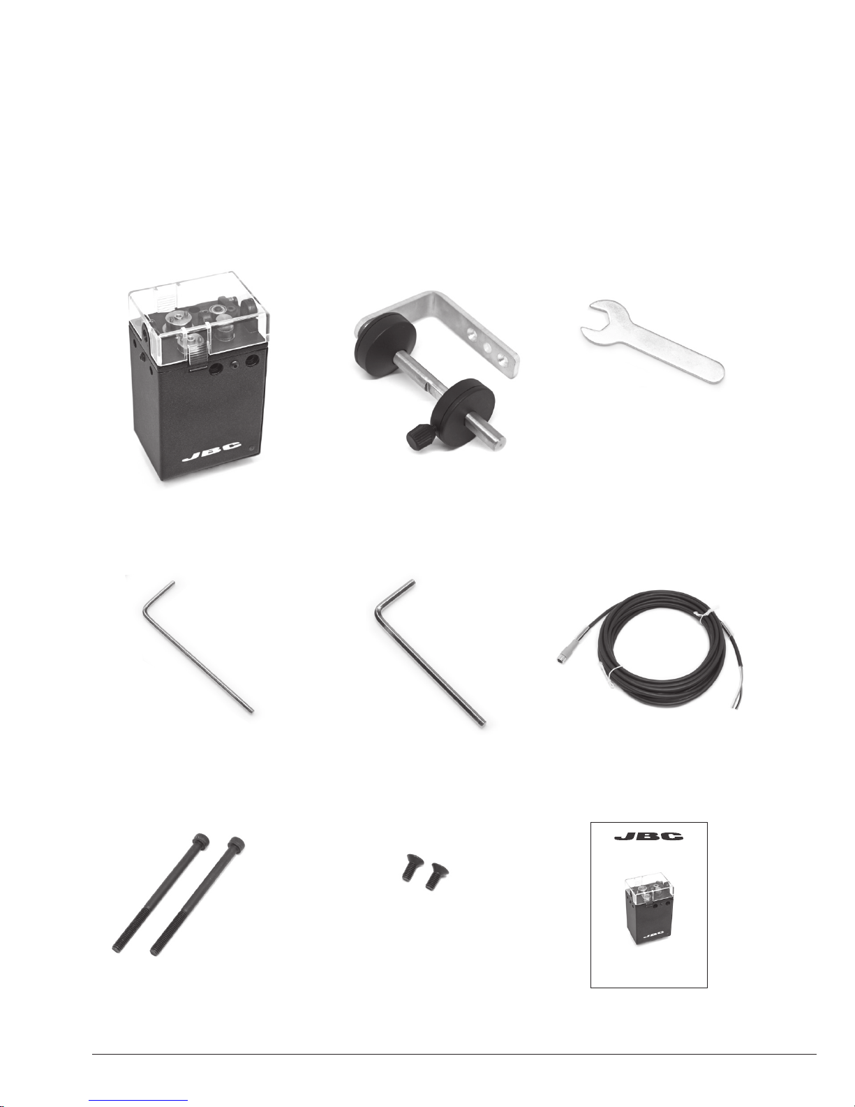
Packing List
The following items should be included:
Manual ............................ 1 unit
Ref. 0021348
Allen Key 1,5 mm ......... 1 unit
Ref. 0741610
Reel Support ................. 1 unit
Ref. 0021219
Solder Feeder for
Automation .................... 1 unit
Ref. SFR-A
Communications
Cable 3 m........................ 1 unit
Ref. 0020261
Spanner 10 mm............. 1 unit
Ref. 0017631
Allen Key 2,5 mm ......... 1 unit
Ref. 0012574
Ref. SFR-A
Solder Feeder for Automation
Screws
DIN 912 M4x60.......... 2 units
Ref. 0014954
Screws
DIN 7991 M4x10........ 2 units
Ref. 0490180
Download the Robot Communication Protocol for SFR at www.jbctools.com/jbcsoftware.html
2
www.jbctools.com
INSTRUCTION MANUAL
Page 3
1 3
5
2 4
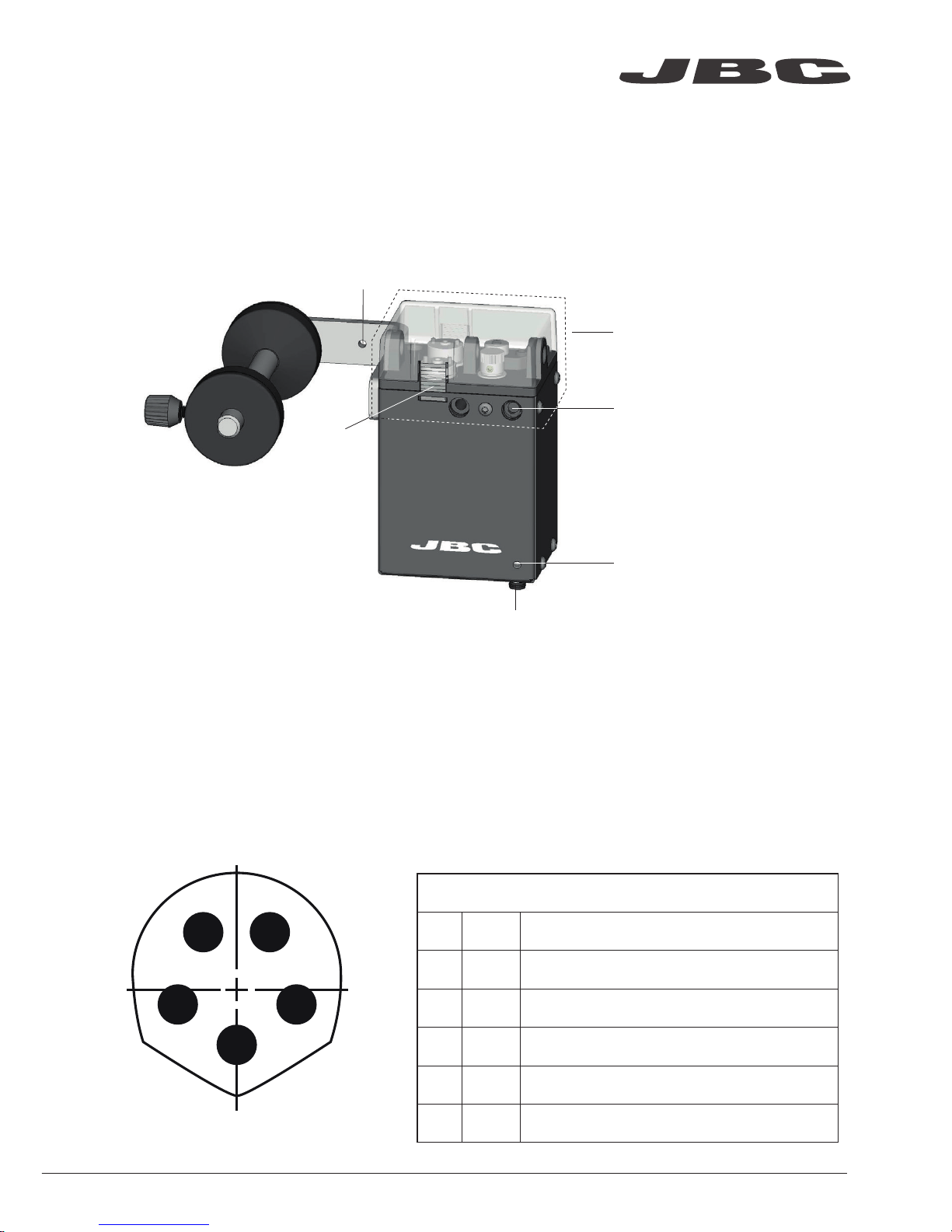
Front view
SFR Communications Connector
Features
Connection
The Solder Feeder for Automation must be controlled by a Robot/PLC/Computer. JBC developed
RS232 Robot Communication Protocol. (Available at www.jbctools.com/jbcsoftware.html)
The SFR-A can be connected with a five-pins communications cable (Ref. 0020261).
See the table below for a description of Communication Connector pin distribution:
Communications Connector
Pin Color Description
1 Brown
Power supply input:
24Vdc (±5%). 1.5 A current required
2 White Serial input: RS232 RX
3 Blue
Common reference:
GND for RS232, power supply and switch.
4 Black
Switch input:
0V or 24V to start feeding. Leave it open to stop.
5 Grey Serial output: RS232 TX
Communications Connector
LED Indicator:
· Blue: device powered
· Green: device working
· Red blinking: error, no solder wire
or device is blocked
Assembling holes
ESD
Safe Connector
The SFR Solder Feeder works together with one of the different GSFR Guide Kits, available for the various solder
wire diameters, with or without solder wire perforation. GSFR kits are sold separately.
Drag mechanism*
Lid with
push tabs
www.jbctools.com
3
Page 4
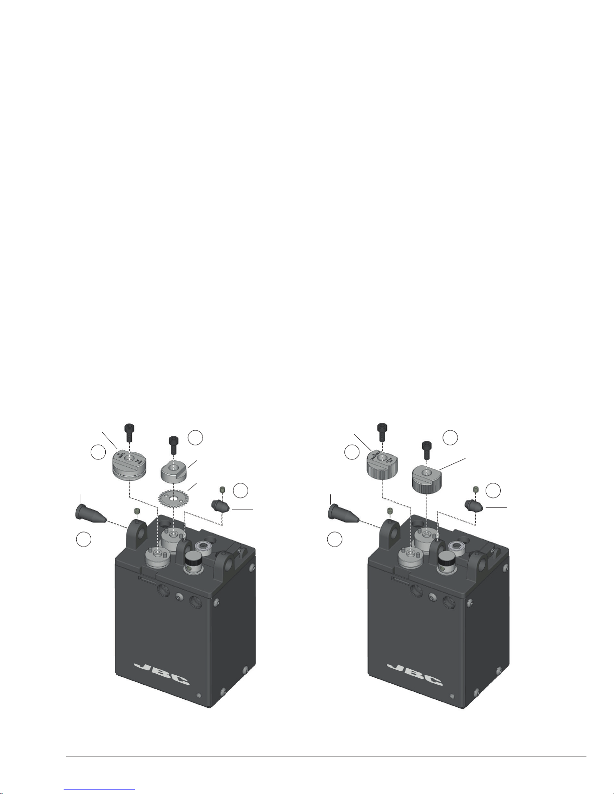
Assembly: GSFR* Wheels to SFR
For this operation, disconnect the device, and dismantle the Cover by pushing the tabs. Use the
allen key and the spanner to assemble the following components.
1. Insert the Intermediate Nozzle until its collar rests against the housing and tighten the screw.
2. Assemble the Guide Wheel and tighten the screw. If you use a Guide Kit without Solder
Wire Perforation assemble the Support Wheel.
3. If you have a Guide Kit with Solder Wire Perforation assemble the Blade first, then mount the
Blade Clamp onto the same axis and tighten the screw. If you use a Guide Kit without Solder
Wire Perforation, assemble the Traction wheel.
Caution: handle the blade carefully to avoid injury.
4. Insert the Inlet Nozzle into the hole and tighten the screw.
1
GSFR* with Solder Wire Perforation GSFR* without Solder Wire Perforation
4
1
2 2
3 3
4
Blade
Blade Clamp
Inlet
Nozzle
Inlet
Nozzle
Guide
wheel
Traction
Wheel
Support
Wheel
Inter.
Nozzle
Inter.
Nozzle
*Not included, sold separately
4
Page 5
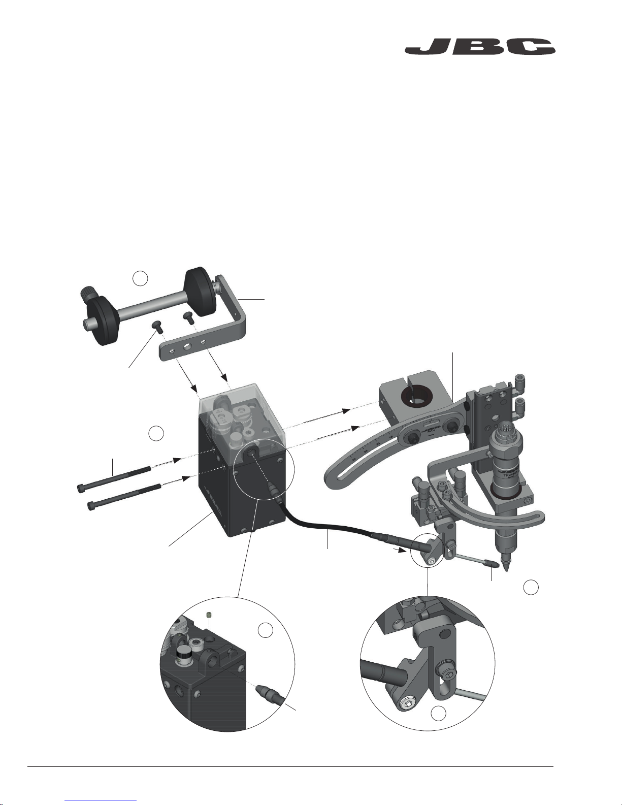
1. Assemble the SFR to the RBA with the screws.
2. Assemble the GSFR Guide Tube to the RBA and tighten the screw.
3. Assemble the Outlet Nozzle onto the Dispensing Tube.
4. Assemble the GSFR Bushing into the SFR hole and tighten the screw.
5. Finally attach the Reel Support to the SFR with its screws.
Assembly: SFR to RBA*
Solder Feeder
for Automation
Ref. SFR-A
GSFR Guide Tube*
Soldering Head
for Automation*
Ref. RBA-A
Reel Support
Ref. 0021219
2
4
5
Screws
Ref. 0014954
Screws
Ref. 0490180
GSFR Bushing*
*Not included, sold separately
Outlet Nozzle*
3
1
www.jbctools.com
5
Page 6
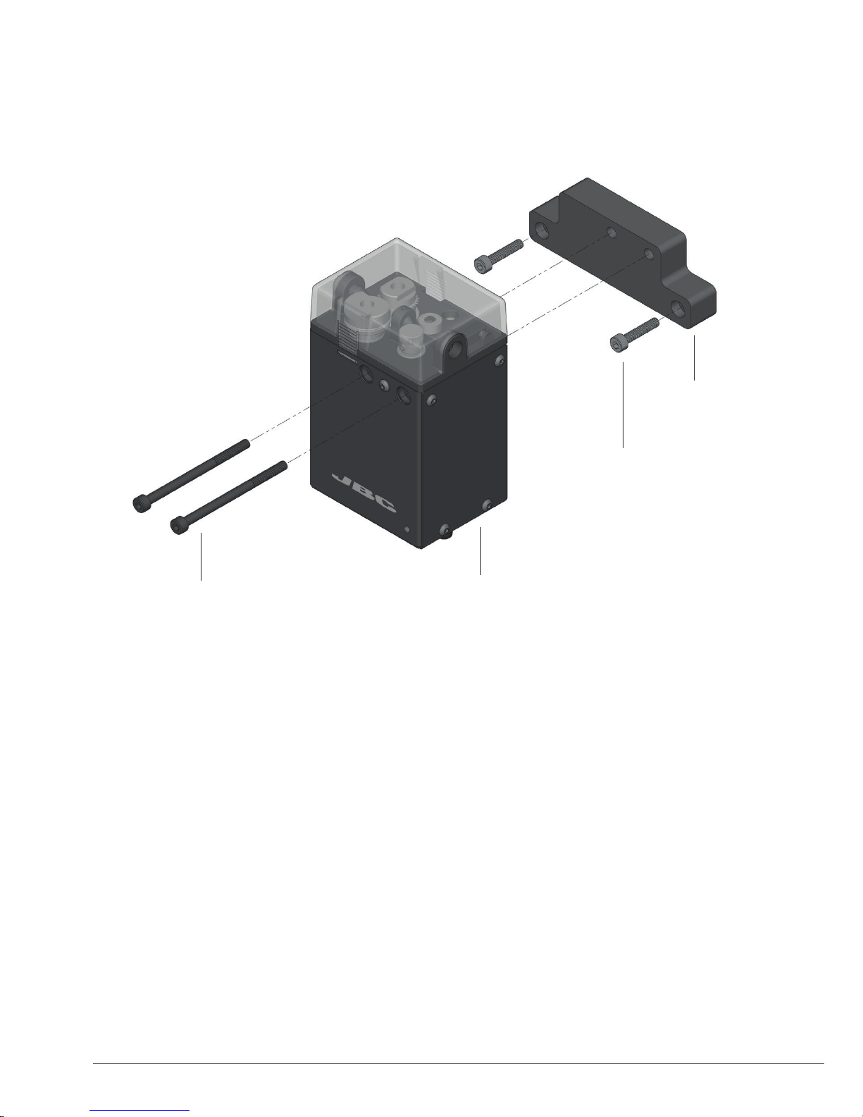
Assembly: SFR independent from RBA*
Screws
Ref. 0014954
Solder Feeder
for Automation
Ref. SFR-A
Insulator*
Ref. 0021713
Screws*
Ref. 0921890
If mounting SFR independently from RBA, the Electrical Insulator is required.
Assemble the Insulator to your device with its screws, followed by the SFR to The insulator with its
screws.
The Electrical Insulator must be assembled for the tool to work properly.
Do not use the SFR without insulator if it is mounted without the RBA.
*Not included, sold separately
6
Page 7
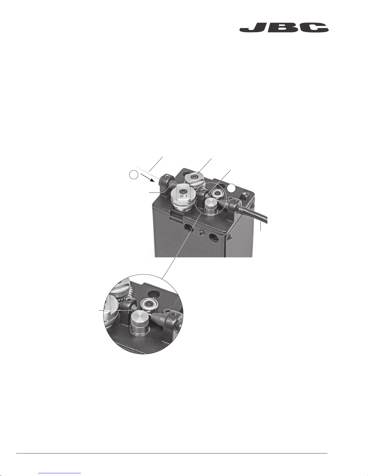
Solder Wire Loading
The GSFR must be assembled previously.
1. Feed the Solder Wire into the Inlet Nozzle until it reaches the wheels.
2. Make sure the wire passes through the Intermediate Nozzle and enters into the Guide Tube.
Wire feeding is controlled by an external controller (Robot/PLC/Computer). See the Robot Communication Protocol for SFR unit at www.jbctools.com/jbcsoftware.htm
Solder Wire
2
1
Wheels
Inlet
Nozzle
Guide
Tub e
Intermediate
Nozzle
Intermediate
Nozzle
www.jbctools.com
7
Page 8

Dimensions
mm
(in)
Solder Wire Reel dimensions: max. lenght 80mm (3.2 in), max. diameter 80mm (3.2 in), max. weight 1 kg (2.2 lb).
8
Page 9
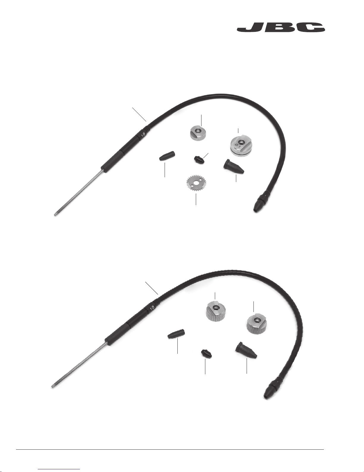
Accessories
Guide Kit for SFR with Solder Wire Perforation
Ref. GSFRXXVXX
Different Guide Kits for different Solder Wire diameters and Tube lengths are available.
More information at www.jbctools.com
Guide Tube
Inlet Nozzle
Guide Wheel
Blade Clamp
Blade
Inter. Nozzle
Inlet Nozzle
Traction Wheel
Outlet Nozzle
Support Wheel
Inter. Nozzle
Guide Tube
Outlet Nozzle
Guide Kit for SFR without Solder Wire Perforation
Ref. GSFRXXDXX
www.jbctools.com
9
Page 10

*Not included, sold separately
Work Place Example
Solder Feeder
Ref. SFR-A
Tip Cleaner*
Ref. CLMR-A
Soldering Head*
Ref. RBA-A
Soldering Iron*
Ref. TR245-A
TR470-A
TR A245-A
TR A470-A
Automatic Cartridge Stand*
Ref. CS2R245-A
CS2R470-A
Control Unit*
Ref. UCR245-5A
UCR470- 5A
Guide Kit*
Ref. GSFR
10
Page 11
It is imperative to follow safety guidelines to prevent electric shock,
injury, fire or explosion.
- Do not use the device for any other purpose.
- Do not leave the appliance unattended when it is on.
- Be sure that the power supply is disconnected before changing any spare part.
- Avoid flux coming into contact with skin or eyes to prevent irritation.
- Be careful of fumes produced while soldering.
- Keep your workplace clean and tidy. Wear appropriate protective glasses and gloves while
handling any component to avoid personal injury.
- Utmost care must be taken with liquid tin waste which can cause burns.
Safety
- Before carrying out maintenance, always unplug the tool and the device.
- Use a damp cloth to clean the Solder Feeder. Alcohol can only be used to clean the metal parts.
- Periodically check all cables and tube connections.
- Replace any defective or damaged parts. Use original JBC spare parts only.
- Repairs should only be performed by a JBC authorized technical service.
Maintenance
www.jbctools.com
11
Page 12

This product should not be thrown in the garbage.
In accordance with the European directive 2002/96/EC, electronic equipment at the end of their life
must be collected and returned to an authorized recycling facility.
Manual in other languages available on our website
www.jbctools.com
Warranty
JBC’s two-year warranty covers this equipment
against all manufacturing defects, including the
replacement of defective parts and labour.
Warranty does not cover product wear or misuse.
In case of any manufacturing defect, the equipment
must be returned, postage paid, to the dealer where
it was purchased. Please, register your product
within 30 days of purchase in www.jbctools.com/
productregistration.
0021348-0618-V05
Specifications
- Net Weight: 870 gr (1.92 lb)
- Dimensions: 114 x 66 x 52 mm (4.49 x 2.60 x 2.05 in)
- Spool Capacity: Up to 1 kg (2.20 lb)
- Solder Wire Reel Dimensions: Max. lenght 80mm (3.2 in), max. diameter 80mm(3.2 in)
- Solder Wire Reel Weight: Up to 1kg (2.2 lb)
- Solder Diameter: Depends on the GSFR Kit used
- Max. Speed: 120 mm/s (4.72 in/s)
- Ambient Operating Temp.: 10 - 40 ºC (50 - 104 ºF)
- Connections: M8-5 pin Commmunication Connector
Complies with CE Standards.
ESD safe.
 Loading...