

Page 1
Auto-Feed Iron
Ref. SF250-A
www.jbctools.com
Page 2
2
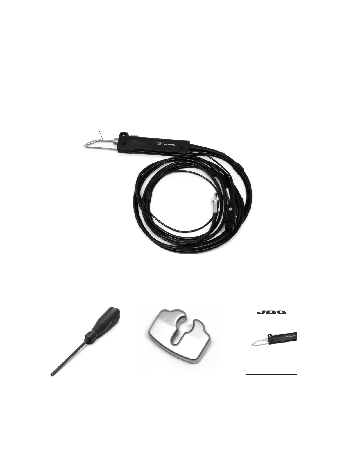
Packing List
The following items should be included:
Auto-feed Iron ........................................................................................................................................... 1 unit
Ref. SF250-B
Includes: C250403 Cartridge
Allen Key 2,5mm .......... 1 unit
Ref. 0780493
Manual ............................ 1 unit
Ref. 0021941
Auto-Feed Iron
Ref. SF250-A
C250403
Stand ............................... 1 unit
Ref. 0004960
www.jbctools.com
Page 3
Stand Cable
Re f. 001128 3
3
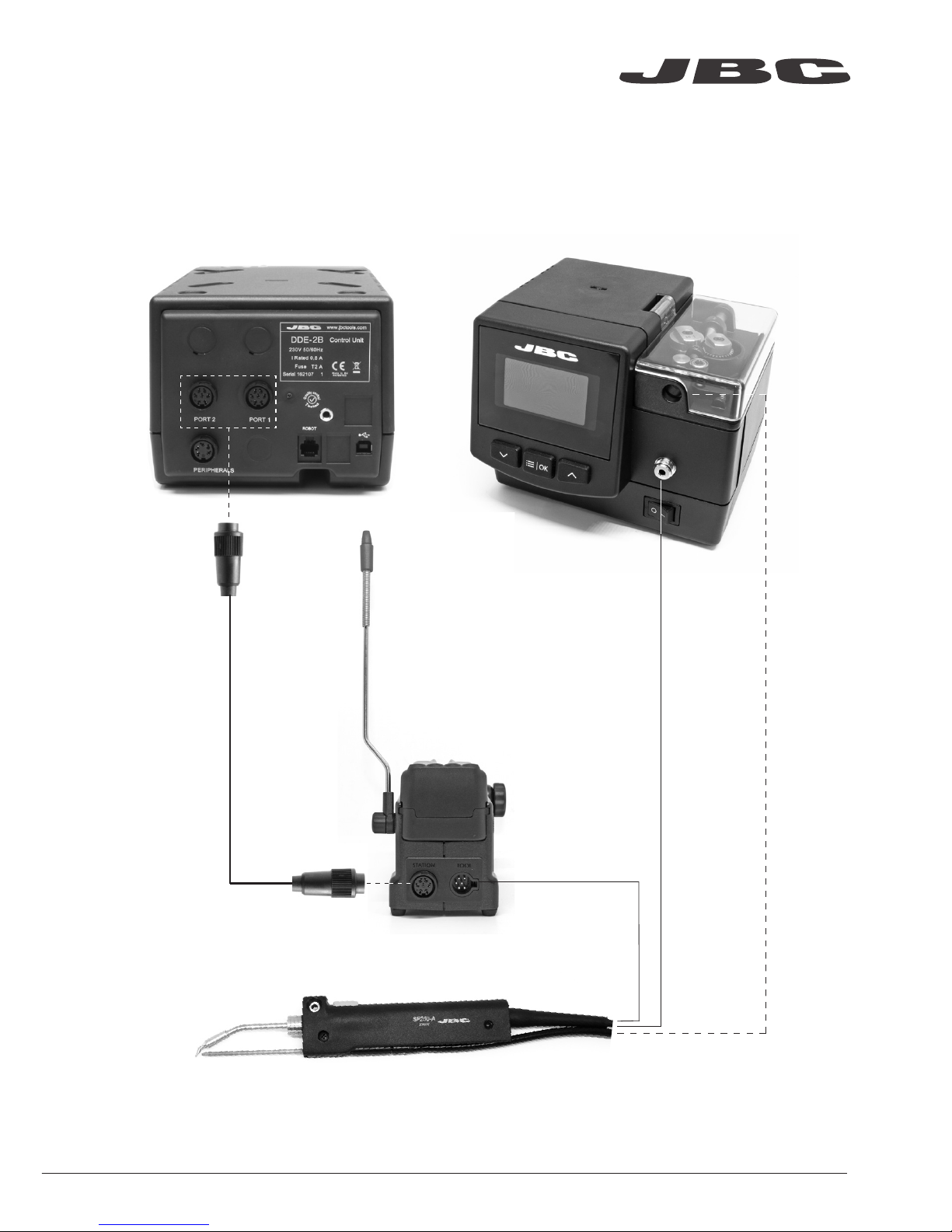
Features
The Solder Feed Iron is connectable to the Solder Feeder SF and a Soldering Station at the
same time, be it a Modular Station or a Compact Station.
Stand
Ref. SF250-SE
Auto-feed Iron
Ref. SF250-A
Solder Feeder
Ref. SF-BControl Unit
www.jbctools.com
Page 4

4
1. Loosen the cartridge screw to release it. Place the new cartridge in the Auto-feed iron.
Mark
Changing cartridge
For a safe cartridge change, unplug the tool or turn the station off before following these guidelines:
2. Align the tip of the cartridge with the solder Guide tube.
Important: It is essential to insert the cartridge till the end for a good connection. Use the mark as
reference. Tighten the cartridge screw.
3. You must leave a gap of 8-10 mm (0.31 - 0.40 in) between the tip and the end of the Guide tube.
4. Loosen the guide screw. Adjust the Guide tube and tighten the screw.
8-10 mm
(0.31 - 0.40 in)
1
2
4
3
Page 5

ø 0,4
ø 0,6
1,8x0,8
ø 0,8
4,8x1,5
1,2x0,7
3,2x1,5
ø 2,2
2,2 x 1
1,2x0,7
2,2x1
4,8x1,5
ø 2,2
ø 3,8
2,2x1
ø 1,7
5
C250-420 C250-401
C250-405
C250-402
C250-406
C250-403
C250-412C250-404 C250-418
C250-409 C250-410
C250-413C250-407 C250-408 C250-411 C250-414 C250-415
The SF250-A Auto-feed Iron works with C250 cartridge range. Find the model that best suits your
soldering needs in www.jbctools.com
Compatible Cartridges
Note: All the cartridges shown are actual size.
www.jbctools.com
Page 6

6
Accessories
Fume Extractor
Ref. F4468 - 2 m (78.74 ft) lenght.
The fume extractor for AL250 is an easy & safe solution to suck the fume generated at the solder joint.
Support
Ref. AL-IA
Page 7

7
Before carrying out maintenance, always allow the equipment to cool.
- Before carrying out maintenance, always unplug the stand and the tool.
- Check periodically that the metal parts of the tool and the stand are clean to ensure detection of
the tool when it is in the stand. Use a damp cloth or alcohol.
- Periodically check all cables and tubes connections.
- Replace any defective or damaged pieces. Use original JBC spare parts only. Repairs should only
be performed by a JBC authorized technical service.
Maintenance
Safety
- Do not use the stands for any purpose other than soldering or rework.
- The power cord must be plugged into approved bases. Be sure that it is properly grounded
before use. When unplugging it, hold the plug, not the wire.
- The tool should be placed in the stand when is not in use in order to activate the sleep mode.
The soldering tip, the metal part of the tool and the stand may still be hot even when the station
is turned off. Handle with care, including when adjusting the stand position.
- Avoid the contact of flux with skin or eyes to prevent irritation.
- Be careful with the fumes produced while soldering.
- Keep your workplace clean and tidy. Wear appropriate protection glasses and gloves while
working to avoid personal harm.
- Utmost care must be taken with liquid tin waste which can cause burns.
- Maintenance must not be carried out by children unless supervised.
It is imperative to follow safety guidelines to prevent electric
shock, injury, fire or explosion.
www.jbctools.com
Page 8

This product should not be thrown in the garbage.
In accordance with the European directive 2002/96/EC, electronic equipment at the end of their life
must be collected and returned to an authorized recycling facility.
Manual in other languages available on our website
www.jbctools.com
Warranty
JBC’s two-year warranty covers this equipment
against all manufacturing defects, including the
replacement of defective parts and labour.
Warranty does not cover product wear or misuse.
In case of any manufacturing defect, the equipment
must be returned, postage paid, to the dealer where
it was purchased.
00 219 41-0918-V 01
Specifications
- Net Weight: 202 gr (0.45 lb)
- Dimensions: 35 x 21 x 182 mm (1.42 x 0.83 x 7.16 in)
- Diameter of solder wire: Ø 0,5 - 1,5 mm (0.02 - 0.059 in)
Complies with CE standards.
ESD protected.
 Loading...