

Page 1
www.jbctools.com
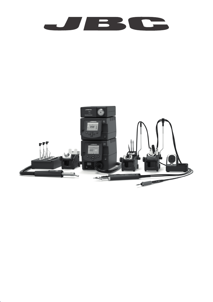
INSTRUCTION MANUAL
Complete Rework Station
with Electric Pump
Ref. RMSE-QE
Page 2
Packing List
The following items are included:
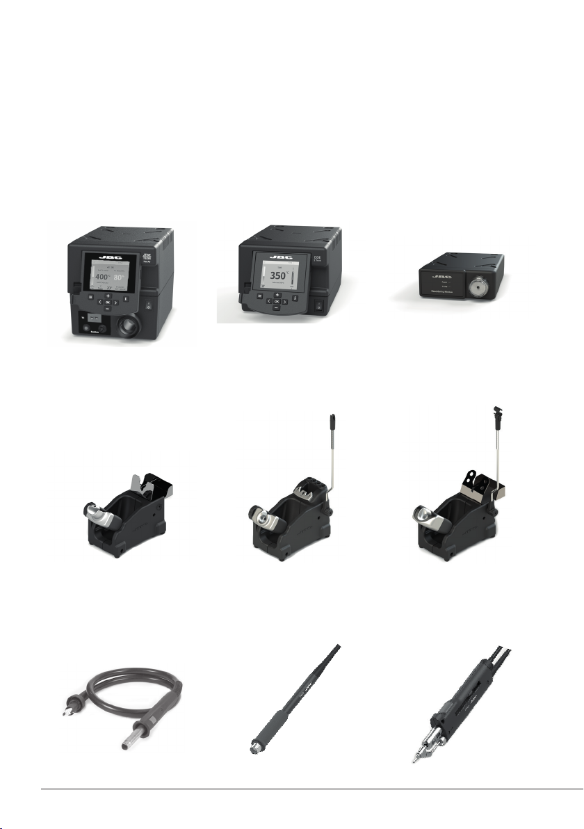
JTSE Control
Unit ....................................1 unit
Ref. JTSE-1A (100V - 120V)
JTSE-2A (230V )
Stand ................................ 1 unit
Re f. J T- SE
DDE Control Unit .......... 1 unit
Ref. DDE-1C (120V)
DDE-2C (230V)
DDE-9C (100V)
Stand ................................ 1 unit
Ref. AD-SE
Electric Desoldering
Module ............................. 1 unit
Ref. MSE-A
Stand ............................... 1 unit
Ref. DR-SE
Heater hose set ............ 1 unit
Ref. JT-T1A (100V / 120V)
JT-T2A (230V )
2
General Purpose
Handle .............................. 1 unit
Ref. T245-A
Desoldering Iron ........... 1 unit
Ref. DR560-A
C560003 already inserted
Page 3
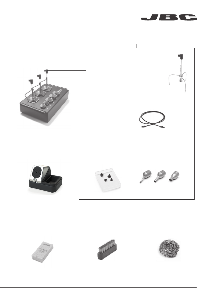
JT Accessory set
Re f. 0 012 332
www.jbctools.com
Extractor stand ............. 1 unit
Ref. 0008752
ESD Tip Cleaner ........... 1 unit
Ref. CL8499
Extractors
Ref. E2184
E2064
E2052
Protectors
Ref. P2220
P2230
P2235
P4000
P4010
Suction Cups
Re f. 093 0110
Ø 10 - 0934050 (x3)
Ø 4.7 - 0934070 (x1)
Trip od
Ref. T2050
(Ø 39mm)
T2250
(Ø 85mm)
Suction Tube
Ref. 0932330
Nozzles
Ref. JN2015 (x1)
JN2012 (x1)
JN2020 (x1)
Sponge ............................ 1 unit
Ref. S0354
Metal Brush ................... 1 unit
Ref . CL6 217
Sponge ............................ 1 unit
Ref. C L6 210
3
Page 4
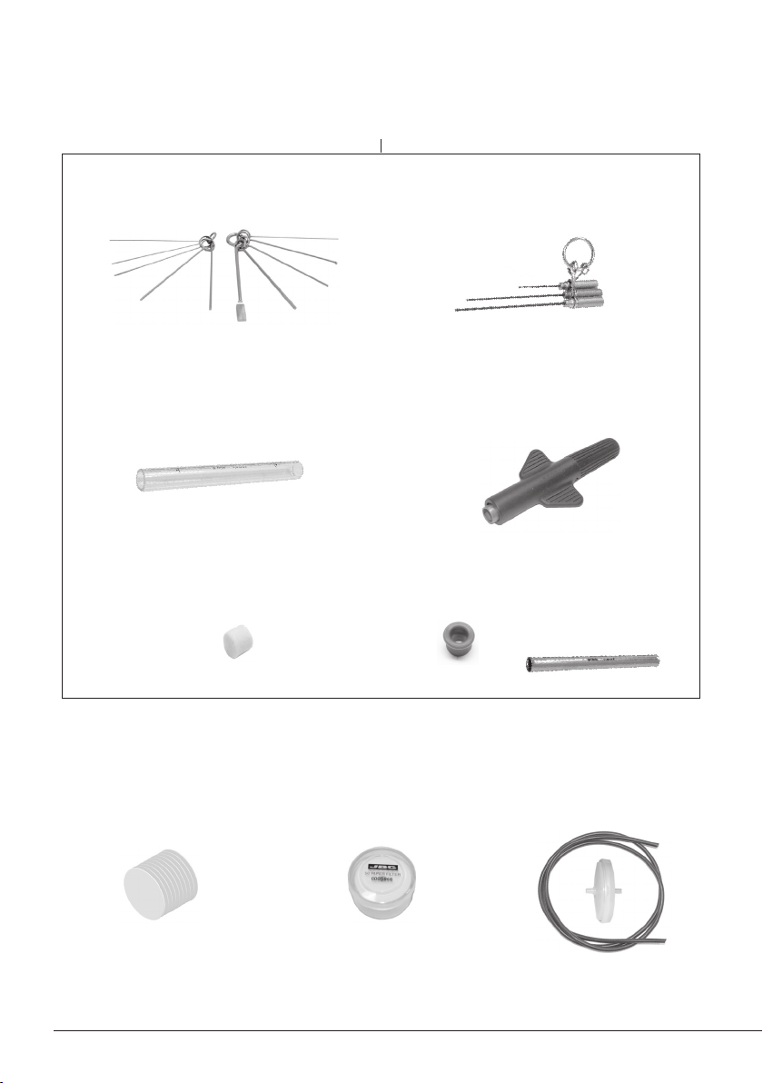
DR560 Accessories
Ref. 002 2819
Tip cleaning set ................................. 1 unit
Ref. 0965970
Glass solder collector ..................... 1 unit
Re f. 0 81262 0
Filter Box ................. 1 unit
Ref. 0780840
It contains 10 filters
Internal gasket .............. 1 unit
Ref. 0019208
It contains 2 gaskets
Long Tip Cleaning set ..................... 1 unit
Ref. 0965760
Spanner ............................................. 1 unit
Ref. 0780550
Metal solder
collector ................... 1 unit
Ref. 0812630
Cotton Filter ................... 1 unit
Ref. 0781046
It contains 10 filters
4
Filter Box .......................... 1 unit
Ref. 0005966
It contains 50 filters
Suction Filter .................. 1 unit
Re f. 08 21830
Page 5
www.jbctools.com
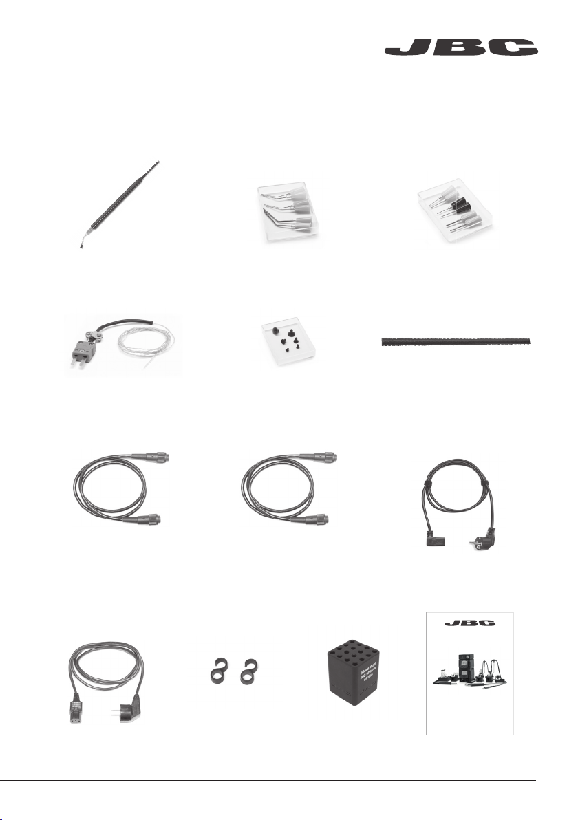
Pick & Place ................... 1 unit
Ref. T260-A
Thermocouple
Typ e K .............................. 1 unit
Ref. PH218
Stand Cable ................. 2 units
Re f. 001128 3
Bent Needles Set ......... 1 unit
Ref. 0861660
Cups Set ......................... 1 unit
Ref. 0940163
Module Cable ................ 1 unit
Ref. 0 014 874
Straight Needles Set ... 1 unit
Re f. 090154 6
Cleaning stick ................ 1 unit
Ref. 0786640
Power cord
For DDE ........................... 1 unit
Ref. 0013671 (100/120V )
0010569 (230V)
Power cord
For JTSE ................. 1 unit
Ref. 0009417 (100V/120V)
0009401 (230V)
Union
Flanges ..... 1 unit
Re f. 00113 5 6
Cartridge
holder .............. 1 unit
Ref. SCH-A
Manual .................1 unit
Ref. 002 314 0
www.jbctools.com
INSTRUCTION MANUAL
Complete Rework Station
with Electric Pump
Ref. RMSE-QE
5
Page 6
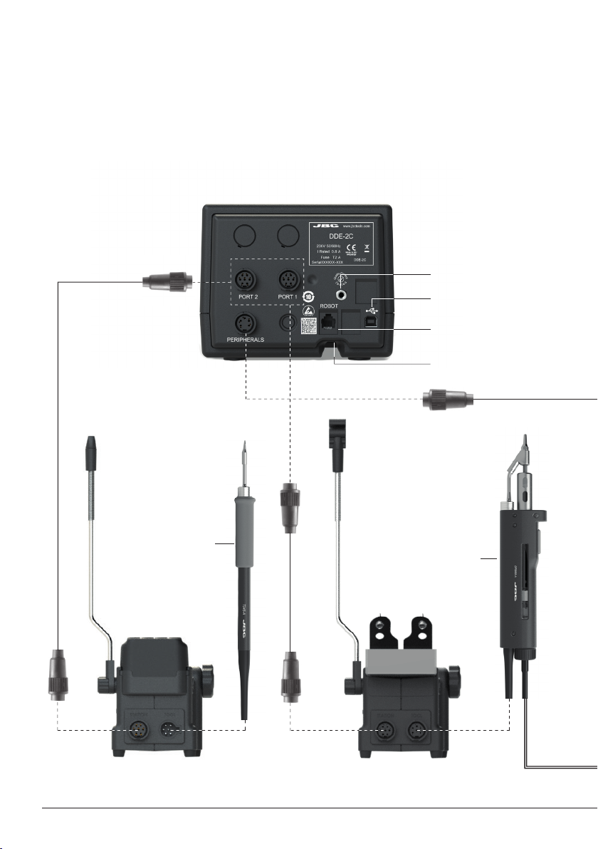
Connections
Work simultaneously with up to 2 tools and join each station port with 1 module + 1 pedal (Peripherals).
Stand Cable
Re f. 001128 3
Equipotential connection
USB-B connector
RJ12 connector for Robot
Power Socket
General
Purpose
Handle
Ref. T245-A
Stand
Ref. AD-SE
Desoldering Iron
Ref. DR560-A
Stand
Ref. DR-SE
6
Page 7
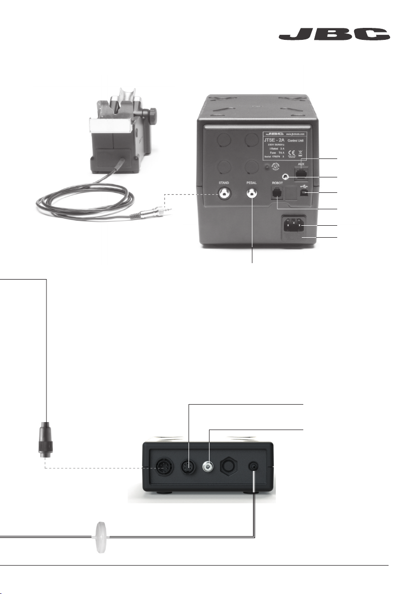
JTSE Connection
Stand
Re f. J T- SE
www.jbctools.com
Auxiliar
connector
Equipotential
connector
USB connector
Robot RS232
connector
Power Socket
Fuse
To Pedal
Ref. P-005* or P-405*
*Not included
Module Cable
Ref. 0 014 874
Suction Filter
Re f. 08 21830
Electric Desoldering Module
Ref. MSE-A
To another peripheral
To Pedal
Ref. P-005* or P-405*
*Not included
7
Page 8
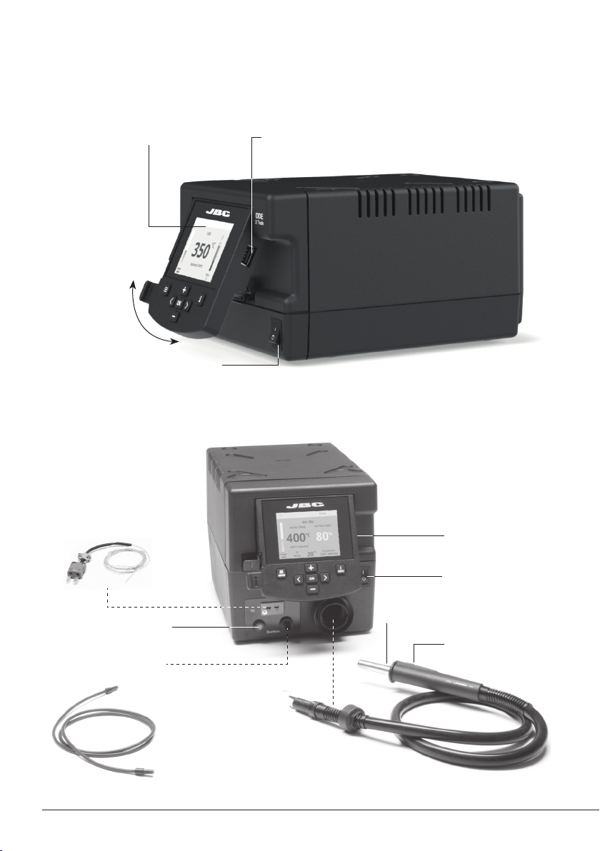
DDE Features
Tilt the display
for easy reading
JTSE Features
USB-A connector2,8” Color TFT screen
Main switch
Thermocouple type K
Ref. PH218
Activates the suction pump
Suction Tube
For tripods and extractors
8
USB-A connector
Main Switch
Heating element
Hot Air button
(On / Off )
Heater Hose set
Re f. J T-T1A (10 0V/12 0V)
JT-T2A (230V )
Page 9
www.jbctools.com
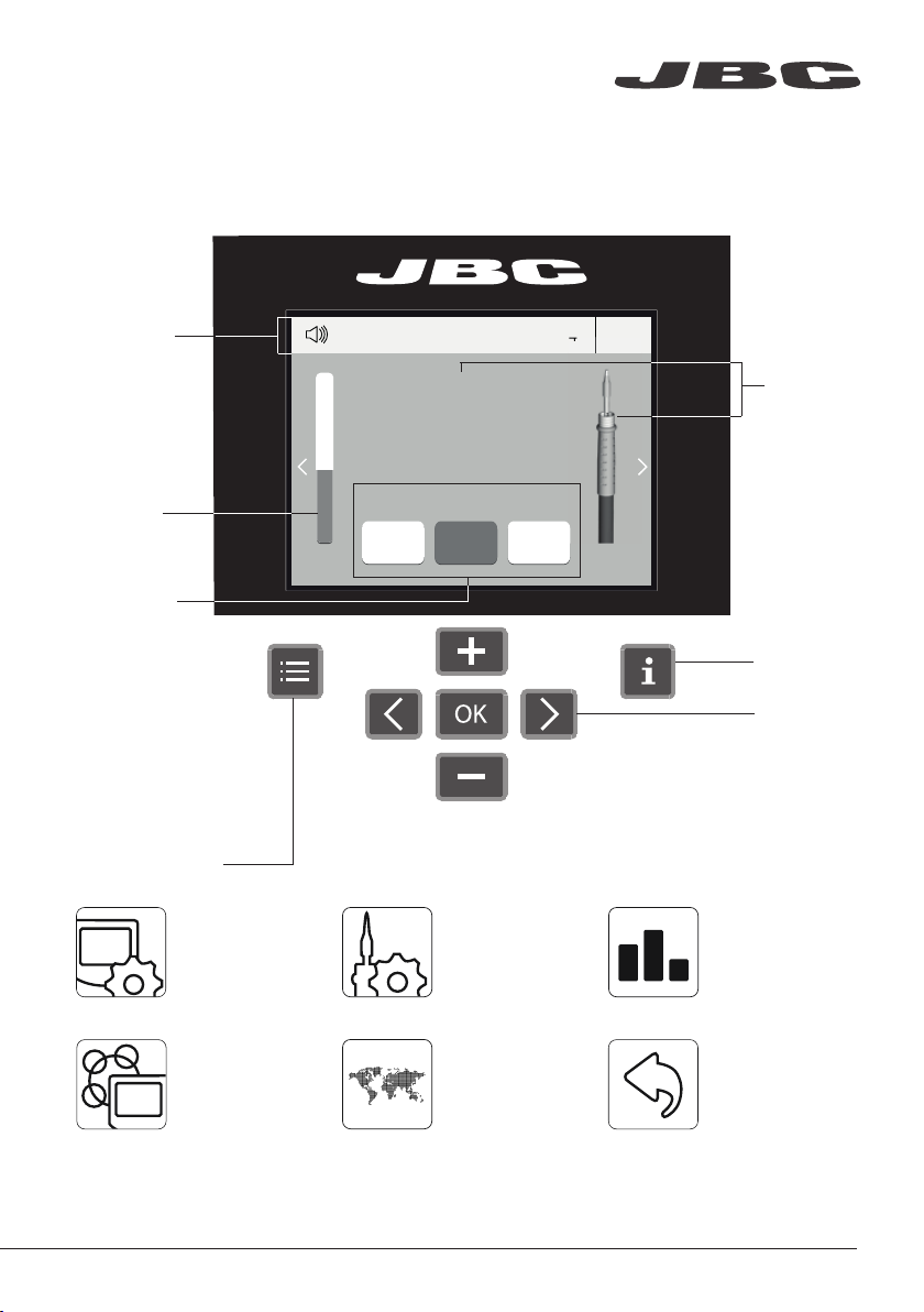
DDE Work Screen
The DDE offers an intuitive user interface which provides quick access to station parameters.
Default PIN: 0105
Status bar
Power
indicator
Displayed if
temperature
levels are
activated
Menu Options
Set the station
parameters
Power
Power
45%
45%
17:14
17:14
T245
T470
ºC
ºC
350
380
Temp. Levels
Temp. Levels
250 350
250 380 400
Set the tool
parameters
380
Port
Port
Tool
in use
1
1
Station
Information
Change
port
Display the hours
worked in each cycle
Station Tools Counters
Consult / modif y the
links of the peripherals
connected to the
station with the por t
they are connected to.
It is possible to
choose the language
from a list.
ResetLanguagePeripherals
Allows you to carry
out an overall station
reset restoring all the
parameters to their
default values.
9
Page 10
Advanced functionalities
It provides detailed graphics of tip temperature and power delivery in real time during
solder joint formation for analysis purposes. This helps you decide how to adjust your
process or which tip to use to obtain the best quality soldering.
Graphics
Designed to avoid thermal shock when soldering Ceramic Chip components like
MLCC, this new and unique feature allows controlling the heating ramp up rate of the
tool to gradually increase the temperature of the
component through all the phases of the soldering process. Up to 25 fully confi gurable
Profi les
JBC Net
Files
soldering profi les can be stored.
The fi rst system to optimize traceability in soldering
- Get greater quality and control in your production
- Manage your whole soldering process remotely in real time
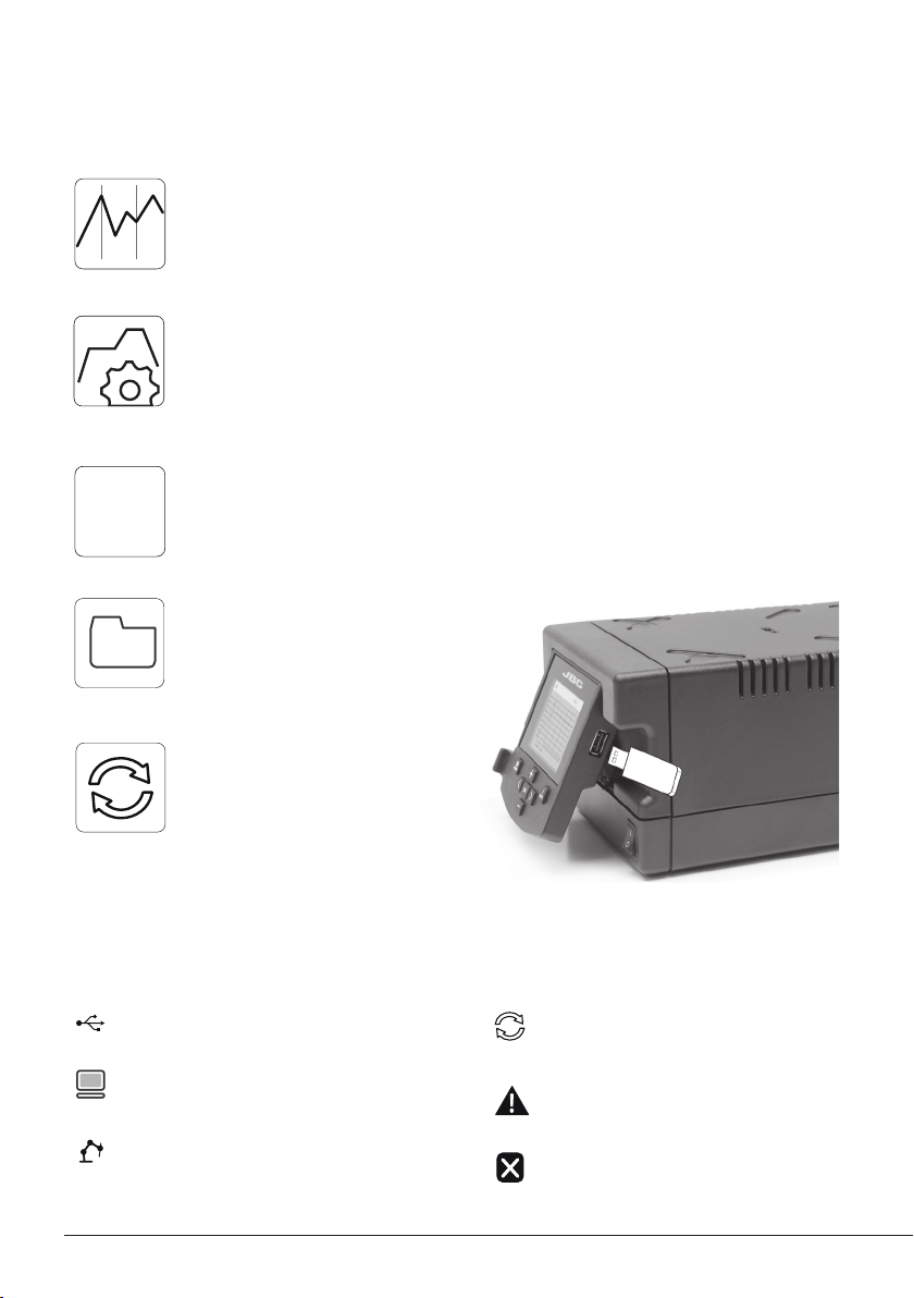
Export graphics
Insert a USB flash drive into the
USB-A connector to save your
soldering process in csv format.
Station update
Download the JBC Update File from
www.jbctools.com/software.html
Update
Insert the USB flash drive with the
file downloadedto the station.
System notifications
The following icons will be displayed on the screen’s status bar.
USB fl ash drive is connected.
Station is controlled by a PC.
Station is controlled by a robot.
10
Station sof tware update.
Press INFO to start the process.
Warning.
Press INFO for failure description.
Er r or.
Press INFO for failure description,
the type of error and how to proceed.
Page 11

MSE Initial Set up
www.jbctools.com
1. After connecting the module, enter the
Peripherals Menu and select the port which
you want to join with the module.
2. Select the module from the list of peripheral
connections. Remember your first connection
is denoted as “a”, the second being “b”, etc.
(e.g. MS _a, M S_b,...).
3. Press Menu or Back to save changes.
Pedal Initial Set up*
1. Enter the Peripherals Menu and select the
port which you want to join to the pedal.
17:14
Peripherals
Pedal PD_a
Module MSE
Port 2-PA
17:14
Peripherals Port 2-DR
Pedal None
Module None
2. Select the pedal from the list (Note that your
first connection is denoted as “a”, the second
being “b”, etc. (e.g. PD_a, PD_b,...).
Peripherals
Pedal PD_a
Module MSE
Module
MSE_a
None
17:14
Port 2-PA
Pedal
PD_a
PD_b
None
3. Set the pedal function according to your work needs:
Select how the pedal
acts: as Sleep,
Extra ctor (hibernation)
or as a module switch.
Select the activating
mode of the pedal
Peripherals Port 2-PA
Pedal PD_a
Function Extractor
Mode released
Minimum time 0 sec
Back
17:14
Set the duration
of the activation
time when pressing
the pedal once**.
For continuous
functioning keep the
pedal pressed.
(pressed/released)
*Ref. P-005 (Not included)
**NB: The same can be applied inversely when continually pressing the pedal and releasing to activate.
11
Page 12

MENU
17:14
?
Port
MENU
17:14
?
Operation
The JBC Most Efficient Soldering System
Our revolutionary technology is able to recover tip temperature extremely quickly. It means the user
can work at a lower temperature and improve the quality of soldering. The tip temperature is further
reduced thanks to the Sleep and Hibernation modes which increase up to 5 times the life of the tip.
3. Hibernation1. Wor k 2. Sleep
Long period
in the stand
When the tool is lifted from
the stand the tip will heat up
to the selected temperature.
17:14
MENU
?
C245-003
ºC
350
Selected 350º
Power
45%
+
Tools Menu:
· Adjust temperature limits and
cartridge.
· Set temperature levels.
Port
3
When the tool is in the stand,
the temperature falls to the
preset Sleep temperature.
Sleep
T
ool in the stand
Actual T
Delay to hibernation: 29:30
Tools Menu:
· Set Sleep temperature.
· Set Sleep delay.
(from 0 to 9 min or no Sleep)
emp. 180º
C
Port
3
Port
3
After longer periods of
inactivity, the power is cut off
and the tool cools down to
room temperature.
Hibernation
Actual Temp. 25ºC
3
Tools Menu:
· Set Hibernation delay.
(from 0 to 60 min or no
hibernation)
12
Page 13

Desoldering process
Use a tip with a larger diameter than the pad to achieve maximum aspiration and thermal efficiency.
www.jbctools.com
1. Placing 2. Rotating
Place the tip over the
lead.
If any solder remains are left on a terminal after desoldering it, resolder it with fresh solder and
repeat the desoldering operation.
If desoldering tips does not provide enough heat to desolder leads from ground planes, consider
using a preheater PCB.
When the solder
melts, gently move
the tip in a circular
motion.
3. Aspirating
Press and hold the
tool button to start the
suction and continue
the movement
completing 3 o 4
circles.
4. Removing
Remove the tip
while maintaining
the suction to make
sure all the solder is
removed from the
joint.
Quick Tip Changer
Save time and change cartridges safely without switching the station off. Be careful, the cartridges
may be hot, when placing them in the storage rack.
1. Removing 2. Inserting 3. Fixing
Place the cartridge in the
extractor and pull the handle
to remove it.
Important: It is essential to
insert the cartridge as far as the
mark for a proper connection.
Place the handle on top
of the new car tridge and
press down.
Mark
D
B
A
Use the holes to fix the
cartridge as follows:
A. For curved C210
B. For C245
C. For straight C210
D. cartridge Storage rack
C
13
Page 14

DR560 Changing Tips
1. Removing
Unscrew the tip using the spanner
supplied.
2. Inserting
Fit the new tip and tighten with the spanner
to make sure it is air tight.
The DR560 uses C560 tips.
Find the model that best suits your soldering needs in www.jbctools.com
Glass Solder Collector Cleaning
1. Removing the lid
Check
internal joint
Check filter
Lid
The lid must be unscrewed with the DR560 in
a vertical position.
3. Inserting the glass solder collector
2. Cleaning
Remove the coil and clean the inside of the
glass solder collector with the cleaning stick.
Check the filter and replace it if it is dirty
or damaged.
The glass solder collector must be inserted
with coil filter in place, positioned between the
2 lines marked.
Then the whole unit must be closed by
screwing the lid.
14
Marks
Page 15

DR560 Maintenance
www.jbctools.com
Tip Care
The intake tube should be periodically cleaned with the largest rod possible.
Important
DO NOT press the vacuum pump button while tinning the desoldering tip, as the fumes given off
by the flux would quickly block the ducts and the air filter.
MSE Changing the pump filters
- Keep the casing clean by using a damp cloth. Periodically check all cable and tube connections.
- Keep filters clean to ensure proper solder suction and replace them when necessary.
Important
Do not use sharp
pointed objects
to open the
suction filter.
Suction filter
Re f. 08 21830
Cotton filters
Ref. 0781046
O Ring
Ref. 0007717
Filter cover
Ref. 0004710
Spare filters
Ref. 0005966
15
Page 16

Tip Cleaner
Improve thermal transfer by cleaning the tip after each solder joint.
Brass wool
Ref. C L6 210
Very ef fective cleaning
method. It leaves a small
layer of solder on the tip to
prevent oxidation bet ween
cleaning and rewetting.
Splashguard
Ref . 0017576
It prevents splashing of
solder particles when
using the brass wool.
Antisplash
Membrane
Ref. 0 0175 74
Prevents splashing
to maintain the
work area clean.
ESD Tip Wiper
Ref. CL0240
A temperature resistant
receptacle lets the
operator remove
excess solder by gentle
tapping or wiping.
Sponge
Ref. S0354
The least harmful
cleaning method. Keep
the sponge damp with
distilled water when
working to avoid tip wear.
Non-slip base
No need to hold the
base while cleaning tips.
Tapping: Wiping:
Tap to remove excess solder. Use the slots to remove remaining particles.
16
Page 17

www.jbctools.com
JTSE / TESE Work Screen
The JTSE /TESE offers an intuitive user interface which provides quick access to station pa rameters.
Default PIN: 0105
Status bar
Instant power
supplied to
heater
Current
air
temp.
Air
temp.
selected
Current
Externa l
TC temp.
Menu Options
Set the station
parameters
4m 38s
Hot Air Temp. Air Flow Selec.
ºC
400
400ºC Selected
Power
45%
TC
Temp.
20
Set the tool
parameters
80
ºC
120ºC Selected
17:14
%
Protection
Status
indicator
Selected
Air flow
Selected
External Tc
temp.
Station
Information
Display the hours
worked in each cycle
Station Tools Counters
It is possible to
choose the language
from a list.
ResetLanguage
Allows you to carry
out an overall station
reset restoring all the
parameters to their
default values.
17
Page 18

Point
2/5
Temp
250
ºC
Flow
60
%
Time
2m 30s
3m 18s
Hot Air Temp
240
ºC ºC %
Ext. TC Temp
20
Air Flow
80
3m 18s
Advanced functionalities
To work with profiles it is essential to use the RWB / RWS / RWT rework arms. The
Rework Arms supports the Hot Air Heater maintaining the distance and position to
the component.
Profiles
Profile name
Current
air temp.
Edit Mode
In this mode you can set up or edit as many as 25 profiles of temperature and air flow.
Current
air flow
Current
Externa l
TC temp.
Data for
these points
18
Menu
Options
· Add point
· Delete point
· Load profile
· Save profile
· Exit
Page 19

450
400
350
300
250
150
100
50
200
Power Temp
Graphics
Power (%)
Temperature
JBC Net
Files
Update
www.jbctools.com
By pressing Graphics in the main MENU, temperature and power fi gures in real time
are displayed. This helps you decide which tip to use to obtain the best quality solder
joints.
17:14
Ext. te mp
Externa l
temp.
The fi rst system to optimize traceability in soldering
- Get greater quality and control in your production
- Manage your whole soldering process remotely in real time
Export graphics
Insert a USB flash drive into the USB-A
connector to save your soldering process
in csv format.
Station update
Download the JBC Update File from
www.jbctools.com/software.html
Insert the USB flash drive with the file downloadedto the station.
System notifications
The following icons will be displayed on the screen’s status bar.
USB fl ash drive is connected.
Station is controlled by a PC.
Station is controlled by a robot.
Station sof tware update.
Press INFO to start the process.
Warning.
Press INFO for failure description.
Er r or.
Press INFO for failure description,
the type of error and how to proceed.
19
Page 20

Adjustable Stand
Adjust the tool holder angle to suit your work position.
Operation Modes
1. From the Tool Settings Menu, select the Start mode to activate the tool depending on the task.
Tool button
Press
Press the start/stop button to blow hot air. Set pedal mode (press once or press
2. The tool stops blowing when pressing the start/stop button.
If the stand is connected to the station and for safety it will also stop when returned to the stand.
Pedal
Press
continuously) depending on the task.
P-005* and P-405* pedals are compatible with
JTSE station.
*Not included. See our website.
20
Page 21

Operation
www.jbctools.com
Position the extractor with the
appropriate suction cup and
press the suction button.
2. Heating
Heat the component.
3. Extracting1. Placing
The component lifts off
automatically when the
solder melts.
Protectors & Extractors
For small components (fig. 1 and 2). For large components (fig. 3 and 4).
We recommend using the protector + tripod We recommend using the manual extractors
1 2 3 4
21
Page 22

Pick & Place (not supplied with JT)
This tool helps you place and remove SMDs of any size easily thanks to the suction pump.
Pick & Place
Ref. T260-A
Bent Needles Set
Ref. 0861660
Straight Needles Set
Re f. 090154 6
Operation
Choose the needle and the suction cup that best fits the component and start as follows:
Press the button to
start/stop the suction
Suction cups
1. Suction 2. Release
Maximum working temp: 250º C (482ºF)
Insert the needle with
the appropriate cup
for a correct suction
process.
22
Make sure the needle
does not protrude
from the cup.
Once the suction is
activated, cover the
pen hole with your
finger and lift off the
component.
Lift your finger to
release the component.
Page 23

Accessories
www.jbctools.com
Protectors
* Ref. AxB (mm) AxB (in) * Ref. AxB (mm) AxB (in)
P3353 4,3 x 3 0.1 6 x 0.12 P1249 12 x 23 0.47 x 0.9
P3786 5,2 x 5,2 0.20 x 0.20 44 P4000 12,5 x 12 ,5 0.49 x 0.49
P3352 5,2 x 7,5 0.20 x 0.29 P3354 13, 2 x 13, 2 0.52 x 0.52
P3355 5,2 x 9,5 0.20 x 0.37 P4025 13,5 x 21,5 0.53 x 0.85
P3356 6,2 x 4,2 0.24 x 0.16 48 P2230 15 x 15 0.59 x 0.59
P3785 7, 2 x 7, 2 0.28 x 0.28 60 P4 010 17 x 17 0.67 x 0.67
P3784 8,2 x 8,2 0.32 x 0.32 P4 005 18 x 29 0.71 x 1.14
P4035 9 x 13 0.35 x 0.51 P4030 18,5 x 18 ,5 0.73 x 0.73
P4040 9,5 x 19 0.7 x 0. 74 P1068 18,5 x 24 0.73 x 0.94
P4080 9,5 x 21 9.5 x 0.83 P2685 28,5 x 28,5 1.12 x 1.12
32 P2220 10 x 10 0.39 x 0.39 P4085 31, 5 x 31,5 1. 24 x 1. 24
P4045 10,5 x 21 0.14 x 0.82 P2 672 33 x 46 1. 30 x 1.18
P4090 11 x 16 0.43 x 0.63 P40 02 50 x 50 1.97 x 1.97
24 P2235 12 x 17 0.47 x 0.67 P3357 52,5 x 14 2.06 x 0.55
Extractors
* Ref. AxB (mm) AxB (in) * Ref. AxB (mm) AxB (in)
52 E2052 20 X 20 0.79 x 0 .79 E 40 15 31,5 X 31,5 1.24 x 1.24
64 E2064 20 X 26 0.79 x 1.02 E2084 33 X 33 1. 3 0 x 1.3 0
80 E2184 24 X 24 0.94 x 0.94 E2 100 38 X 38 1.5 0 x 1.50
E2068 27 X 27 1.0 6 x 1.06 E212 4 45 X 45 1.7 7 x 1.77
E4020 28,5 X 28,5 1.12 x 1 .12
Trip ods
Ref. øC (mm) øC (in)
T2050 39 1.5 3
T2250 85 3.35
Manual extractor
Ref. øD (mm) øD (in)
E2190 7 0.27
øD
* Reference Desk
23
Page 24

Using the Thermocouple type K
Connect a TC type K (PH218) to the station and use it as a protection or regulation sensor.
You can define its use mode by means of the “Ext TC mode” option in the “Tool” menu.
You can choose from two work modes:
Regulation: the station regulates the air
temperature automatically to maintain the
External Thermocouple (TC) temperature.
Fix the TC with Kapton Tape (Ref. PH217) as near as possible to the component being worked on.
If Kapton tape is not ESD you must use an ionizer.
IPC* does not recommend exceeding ramp-up rates over 3-4ºC / sec. (5-7ºF / sec) so as to reduce
the risk of thermal stress on the PCB.
Protection: the station cuts the air supply off
when the External Thermocouple (TC)
temperature is reached.
* IPC was founded in the U.S. in 1957 as the Institute for Printed Circuits.
24
Page 25

www.jbctools.com
Quick Nozzle Changer
Changing nozzles quickly and safely.
2
Turn the tool
off and handle with
care. The heating
element and the
nozzle are still hot.
Compatible Nozzles
The JT-TA works with JT nozzles. Find the model that best suits your soldering needs in www.jbctools.com
Straight Bent Flat
Ø Ø A x B
1
* Ref. Shape Ø Size
(mm)ØSize (in)
* JN2020 Straight Ø 8 Ø 0.31
JN8417 Straight Ø 10 Ø 0.4
* JN2015 Bent Ø 4 Ø 0 .16
* J N2 012 Bent Ø 6 Ø 0.24
JN6633 Bent Ø 8 Ø 0.31
JN7637 Flat 10 x 2 0.4 x 0.08
JN7638 Flat 20 x 2 0.8 x 0.08
JN7639 Flat 30 x 2 1.18 x 0.08
In case of a loosely fitting nozzle:
1. Push the nozzle tab inwards with a screwdriver or flat-nosed pliers.
* Included in JT Accessory set (Ref. 0012332)
2. Insert the nozzle into the JT-TA again.
25
Page 26

Replacing the Heating Element
Only perform this operation when the element is cold and the unit is disconnected from the mains.
1. Loosen the screw.
2. Pull the heating element out of the handle.
3. Connect the new heating element, ensuring it is pushed all the way in.
4. Tighten the screw.
Heating Element
Ref. 0014107 (230V)
0014105 (100V / 120V)
Handle
Ref. 0009829
Heating Hose Set
Ref. JT-T1A (100V / 120V)
JT-T2A (230V )
Changing the JT-TA Heater Hose Set
1. Unplug the power cable.
2. Use a spanner to unscrew the nut.
3. Make sure that the new heater tube fits into
the grooves in the socket.
4. Tighten the screw.
26
Page 27

DDE Compatibility
Select the equipment that best suit your soldering or desoldering needs.
Basic working system Peripherals
Control
Unit
DDE-C
Stand Too l
AD-SE
DN-SE
AP-SE AP250 -A C250
PA-SE PA120-A C120
HT- S E HT420-A C420
DS-SE DS360-A C360
DR-SE DR560-A C560
T210 -A C 210
T245 -A C245
T210- NA* C210
T24 5-N A* C245
* The MNE Nitrogen Flow Regulator is required.
** MSE / MVE Desoldering module required.
Cartridge
Range
MSE-A /
MVE-A
MNE-A FSE-A P-005**
www.jbctools.com
MSE Compatibility
Module To ol
MSE-A
DS360-A C360 DS-SE
DR560-A C560 DR-SE
Cartridge
Range
Stand
Hot Air Stations Compatibility
Basic working system Nozzle Peripherals
Control
Unit
JTSE-A
TESE-B
Too l Heating Element Stand JN Series TN Series P-005
JT- A
TE-B 0012374 (100V/120V/230V) TE-SE
0014107 (230V)
0014105 (100V/120V)
Control Units Peripherals
DDE DME P-005
JT- S E
27
Page 28

Maintenance
Before carrying out maintenance or storage, always allow the equipment to cool.
- Clean the station screen with a glass cleaner
or a damp cloth.
- Use a damp cloth to clean the casing and the
tool. Alcohol can only be used to clean the
metal parts.
- Periodically check that the metal parts of the
tool and stand are clean so that the station
can detect the tool status.
- Maintain tip surface clean and tinned prior to
storage in order to avoid tip oxidation. Rusty
and dirty surfaces reduce heat transfer to the
solder joint.
- Periodically check all cables and tubes.
- Replace a blown fuse as follows:
Clean periodically
Fuse
Fuse holder
1. Pull of f the fuse holder and remove the
fuse. If necessary use a tool to lever it off.
- Replace any defective or damaged pieces. Use original JBC spare parts only.
- Repairs should only be performed by a JBC authorized technical service.
2. Press the new fuse into the fuse holder
and replace it in the station.
28
Fuse holder
Page 29

www.jbctools.com
Safety
It is imperative to follow safety guidelines to prevent electric
shock, injury, fire or explosion.
- Do not use the units for any purpose other than soldering or rework. Incorrect use may cause fire.
- The power cord must be plugged into approved bases. Be sure that it is properly grounded
before use. When unplugging it, hold the plug, not the wire.
- Do not work on electrically live parts.
- The tool should be placed in the stand when not in use in order to activate the sleep mode.
The soldering tip, the metal part of the tool and the stand may still be hot even when the station
is turned off. Handle with care, including when adjusting the stand position.
- Do not leave the appliance unattended when it is on.
- Do not cover the ventilation grills. Heat can cause inflamable products to ignite.
- Avoid the contact of flux with skin or eyes to prevent irritation.
- Be careful with the fumes produced when soldering.
- Keep your workplace clean and tidy. Wear appropriate protection glasses and gloves when
working to avoid personal harm.
- Utmost care must be taken with liquid tin waste which can cause burns.
- This appliance can be used by children over the age of eight and also persons with reduced
physical, sensory or mental capabilities or lack of experience provided that they have been given
adequate supervision or instruction concerning use of the appliance and understand the hazards
involved. Children must not play with the appliance.
- Maintenance must not be carried out by children unless supervised.
29
Page 30

有害物质含量表
产品中有害物质的名称及含量
有害物质
部件名称
铅(Pb) 汞(Hg) 镉(Cd)
烙铁头 O O O O O O
手柄 O O O O O O
电源线 O O O O O O
主机 O O O O O O
电源插座 O O O O O O
保险丝 O O O O O O
主开关 O O O O O O
六价铬
(Cr(VI))
多溴联苯
(PBB)
多溴二苯醚
(PBDE)
电位连接 X O O O O O
变压器 O O O O O O
线路板 X O O O O O
O 表示该有害物质在该部件所有均质材料中的含量均在GB/T 26572 规定的限量要求以下。
X 表示该有害物质至少在该部件的某一均质材料中的含量超出GB/T 26572 规定的限量要求。
30
Page 31

www.jbctools.com
Specifications
Complete Rework station with Electric Pump
RMSE-1QE / RMSE-2QE / RMSE-9QE
J TSE-1A 100V - 120V 50/60Hz. Input fuse: 8A. Rated current: 7A
JTSE-2A 230V 50/60Hz. Input fuse: 4A. Rated current: 3A
- Nominal power: 700W
- Temperature selection: Room temp. / 150 - 450 °C (300 - 840 °F)
Cool mode: T off. Used to blow air to room temperatur
- Ambient operating temp.: 10 - 50 ºC (50 - 122 ºF)
- Air flow regulation: 5 - 50 SLPM
- Vacuum: 30% / 228 mmHg / 9 inHg
- Connectors: USB-A / USB-B
RJ12 for RS232 (Robot)
Pedal for P-005
- Control Unit Weight: 1,9 kg (4.2 lb)
- Control Unit Dimensions: 148 x 184 x 140 mm (5.83 x 7.24 x 5.51 in)
DDE-1A 120V 50/60Hz. Input fuse: 4A. Output: 23.5V
DDE-2A 230V 50/60Hz. Input fuse: 2A. Output: 23.5V
DDE-9A 100V 50/60Hz. Input fuse: 5A. Output: 23.5V
- Temperature Range: 90 - 450 °C (190 - 840 ºF)
- Idle Temp. Stability (still air): ±1.5 ºC (±3 ºF)
- Output Peak Power: 150W per tool
- Tip to ground resistance: <2 ohms
- Tip to ground voltage: <2mV RMS
- Ambient Operating Temperature: 10 - 50 ºC (50 - 122 ºF)
- Connectors: USB-A / USB-B / Peripherals connectors
RJ12 for RS-232 (Robot)
- Control Unit Weight: 3,815 kg (8.41 lb)
- Control Unit Dimensions: 148 x 120 x 232 mm (5.83 x 4.72 x 9.13 in)
MSE-A
- Ambient Operating Temperature: 10 - 50 ºC (50 - 122 ºF)
- Vacuum: 75% / 570 mmHg / 22.4 inHg
- Flow rate: 9 SLPM
- Peripheral Weight: 1,2 kg (2.7 lb)
- Peripheral Dimensions: 145 x 55 x 225 mm (5.71 x 2.17 x 8.86 in)
- Connectors Pedal for P-005
- Total Package: 480 x 340 x 380 mm / 15.90 kg
18.9 x 14.6 x 15.0 in / 35.05 lb
Complies with CE standards.
ESD protected housing.
31
Page 32

Warranty
JBC’s 2 year warranty covers this equipment against
all manufacturing defects, including the replacement
of defective parts and labour.
Warrant y does not cover product wear or misuse.
In order for the warranty to be valid, equipment must
be returned, postage paid, to the dealer where it was
purchased.
Get 1 extra year JBC warranty by registering here:
https://www.jbctools.com/productregistration/
within 3 0 days of purchase.
This product should not be thrown in the garbage.
In accordance with the European directive 2012/19/EU, electronic equipment at the end of its life must
be collected and returned to an authorized recycling facility.
www.jbctools.com
0023140-0819
 Loading...