

Page 1
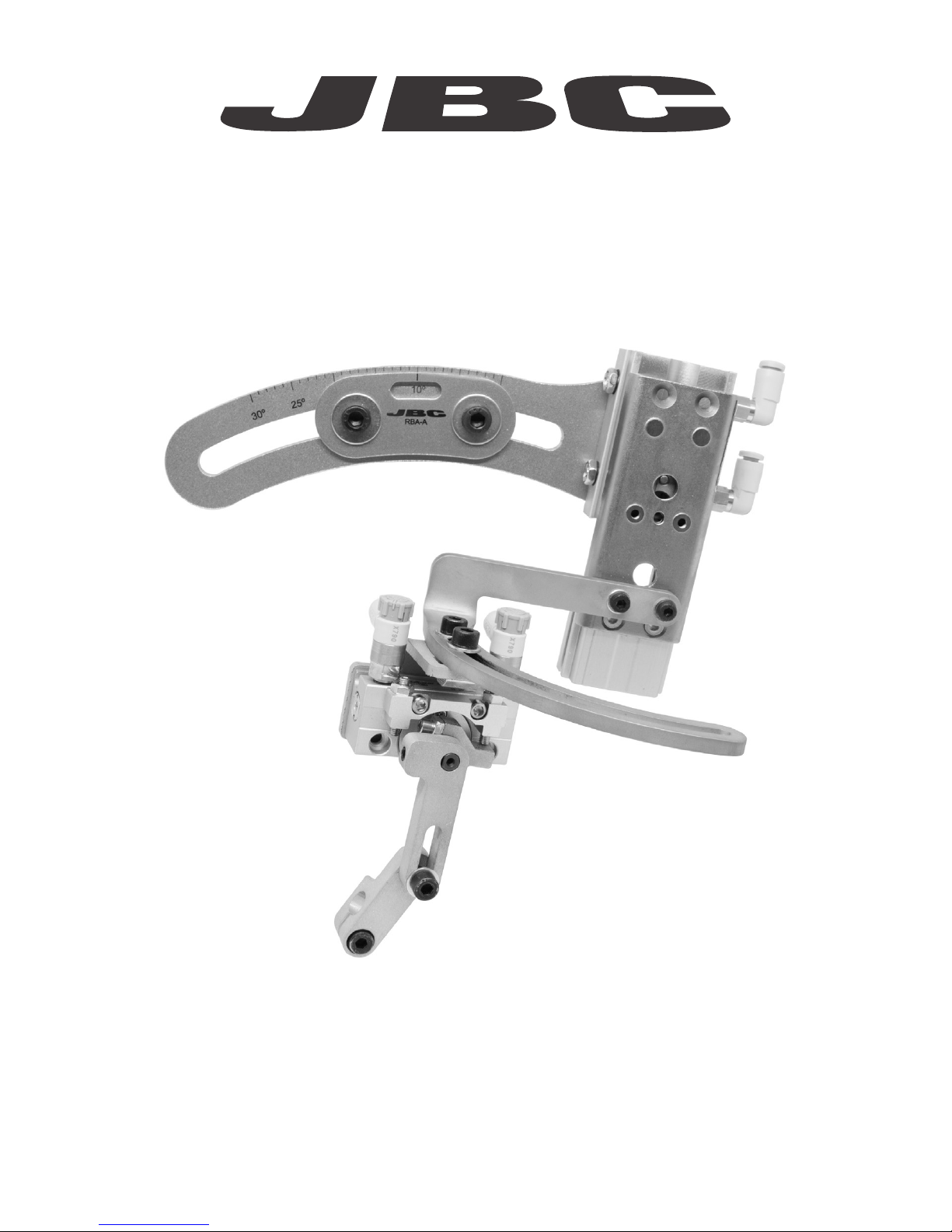
Soldering Head for Automation
Ref. RBA-A
www.jbctools.com
Page 2
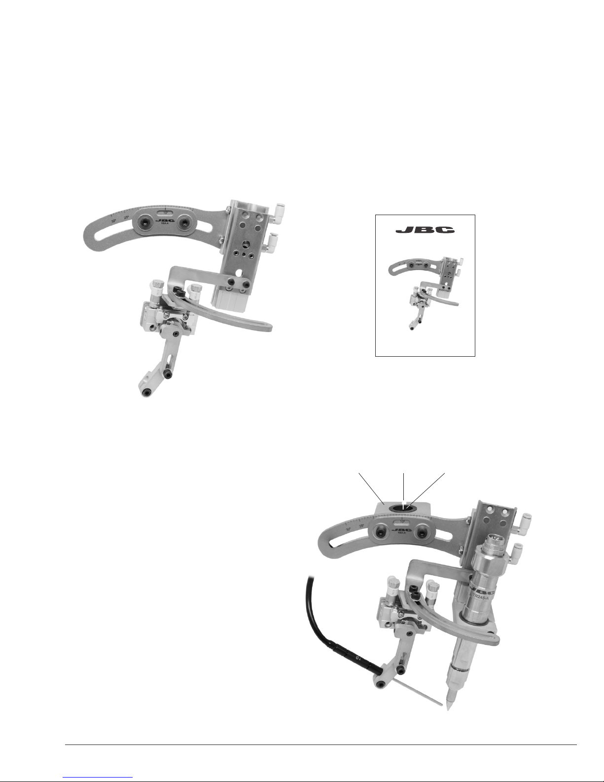
Packing List
The following items should be included:
The Robot needs a 18mm diameter axis to
attach the Soldering Head by using the
Clamp with its Insulator Bushing.
It is mandatory to have the electrical Insulator
Bushing assembled for proper tool working.
Don’t remove the Insulator.
Manual ......................................................... 1 unit
Ref. 0021309
Soldering Head for Automation ............ 1 unit
Ref. RBA-A
Assembly
Clamp Axis Insulator Bushing
2
Ref. RBA-A
Soldering Head for Automation
www.jbctools.com
Page 3
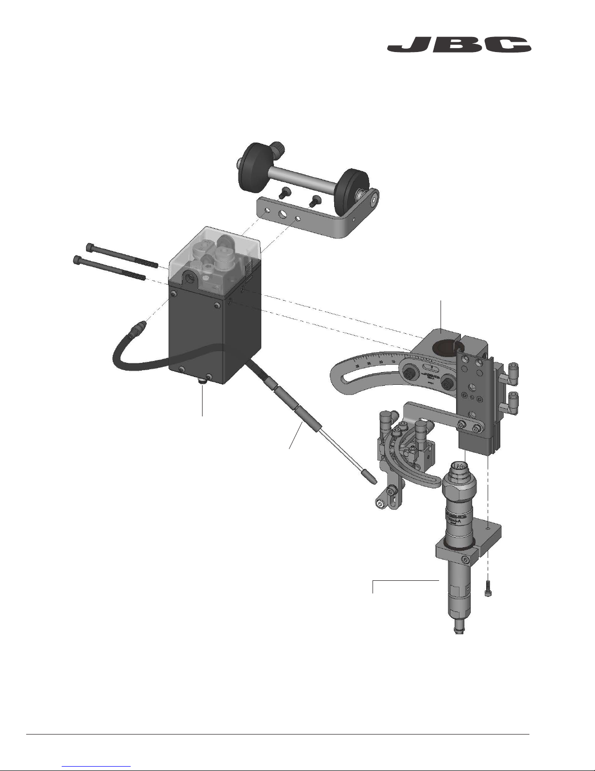
Assembly with TR and SFR
Soldering Head for Automation
Ref. RBA-A
Soldering Iron
for Automation*
Ref. TR245-A
TR470-A
*Not included, sold separately
Solder Feeder
for Automation*
Ref. SFR-A
Guide Kit
for Automation*
Ref. GSFR
www.jbctools.com
3
Page 4
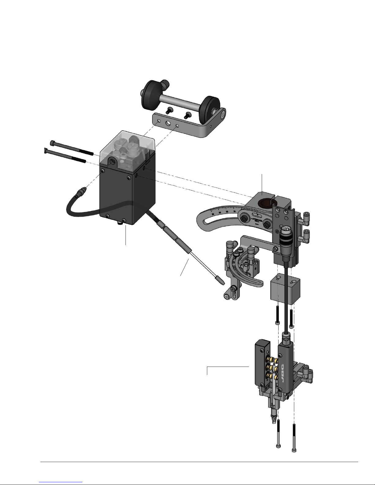
Solder Feeder
for Automation*
Ref. SFR-A
Guide Kit
for Automation*
Ref. GSFR
Soldering Head for Automation
Ref. RBA-A
Automatic Soldering
Iron for Automation*
Ref. T RA245-A
TR A470-A
*Not included, sold separately
Assembly with TRA and SFR
4
Page 5

Adjustment
The Soldering Head for Automation allows adjustment of the Soldering Iron position, as well as
the dispensing Nozzle position.
Soldering Iron position adjustment
0º to 30º
M5 screws
M4 screws
Dispensing Nozzle position adjustment
The angle of the Soldering
Iron is adjustable from 0º to
30º. Loosen and tighten the
M5 screws to change its
position.
The position of the Dispensing Nozzle is adjustable depending on your needs. Loosen and
tighten the M4 screws to change its position.
www.jbctools.com
5
Page 6

B Speed adjustment
Dispensing Nozzle movement adjustment
The movement of the Nozzle Actuator can be adjusted by regulating the following parts:
- By means of the two knobs, the upward A and the downward B movement speed can be
throttled.
- The maximmum angle of the Dispensing Nozzle movement is 90º. This angle can be reduced by
screwing the grub screws C and D .
Compatibility
RBA, SFR, GSFR and CLMR are compatible with R245 and R470 ranges.
Soldering Head
Soldering Irons
TR245 TR470 TRA245 TRA470
RBA
Angle adjustment C
D Angle adjustment
Speed adjustment A
6
Page 7

Movements
The Soldering Head for Automation allows automatic movements through the following pneumatic
actuators:
- Soldering Iron Actuator: with tube connection movement into A and away B from soldering
position.
- Dispensing Nozzle Actuator: with tube connections for movement into C and away D from
feeding position.
The Tool Actuator has a buffer of 5mm stroke to soften collision while soldering.
You can adjust the Dispensing Nozzle Actuator speed by adjusting the fittings.
Tube Connection into
soldering position
Soldering Iron
Actuator
Dispensing
Nozzle Actuator
Tube Connection
into feeding position
Tube Connection
away from soldering
position
Tube Connection
away from feeding
position
Soldering Iron Actuator
Fluid Air
Applicable tubing Ø4mm
Operating pressure 0,15 to 0,7 MPa
Operating speed range 50 to 500 mm/s
Tota l Stro ke 20mm
Dispensing Nozzle Actuator
Fluid Air
Applicable tubing Ø4mm
Operating pressure 0,15 to 0,7 MPa
Operating speed Adjustable
Rotation angle 90º
A
B
D
C
www.jbctools.com
7
Page 8

mm
175,46
6,909
148,48
5,795
25
0,984
49
1,929
74
2,913
18
0,709
61
2,406
Working point
mm
(in)
Dimensions
8
Page 9

*Not included, sold separately
Work Place Example
Solder Feeder*
Ref. SFR-A
Automatic Tip
Cleaner*
Ref. CLMR-A
Soldering Head
Ref. RBA-A
Soldering Iron*
Ref. TR245-A
TR470-A
TR A245-A
TR A470-A
Automatic Cartridge Stand*
Ref. CS2R245-A
CS2R470-A
Control Unit*
Ref. UCR245-5A
UCR470- 5A
Guide Kit*
Ref. GSFR
www.jbctools.com
9
Page 10

It is imperative to follow safety guidelines to prevent electric shock,
injury, fire or explosion.
Maintenance
- Before carrying out maintenance, always unplug the tool.
- Use a damp cloth to clean the tool. Alcohol can only be used to clean the metal parts.
- Periodically check that the metal parts of the tool are clean.
- Periodically check all cables and tube connections.
- Replace any defective or damaged pieces. Use original JBC spare parts only.
- Repairs should only be performed by a JBC authorized technical service.
- Under normal operating conditions, the air actuators lifespan is 10 million cycles. It is recommended
to replace it at the end of its lifespan.
- Do not use the tool for any purpose other than soldering or rework.
- The temperature of accessible surfaces may remain high after the unit is turned off. Handle with care.
- Avoid flux coming into contact with skin or eyes to prevent irritation.
- Be careful with the fumes produced while soldering.
- Keep your workplace clean and tidy. Wear appropriate protection glasses and gloves when
working to avoid personal injury.
- Utmost care must be taken with liquid tin waste which can cause burns.
Safety
10
Page 11

Notes
www.jbctools.com
11
Page 12
This product should not be thrown in the garbage.
In accordance with the European directive 2002/96/EC, electronic equipment at the end of their life
must be collected and returned to an authorized recycling facility.
Manual in other languages available on our website
www.jbctools.com
Warranty
JBC’s two-year warranty covers this equipment
against all manufacturing defects, including the
replacement of defective parts and labour.
Warranty does not cover product wear or misuse.
In case of any manufacturing defect, the equipment
must be returned, postage paid, to the dealer where
it was purchased.
0021309-0718-V01
Specifications
- Net Weight: 576 g (1.27 lb)
- Dimensions: 176 x 148 x 160 mm (6.92 x 5.83 x 6.30 in)
Complies with CE standards.
ESD protected.
 Loading...