

Page 1
Español 11
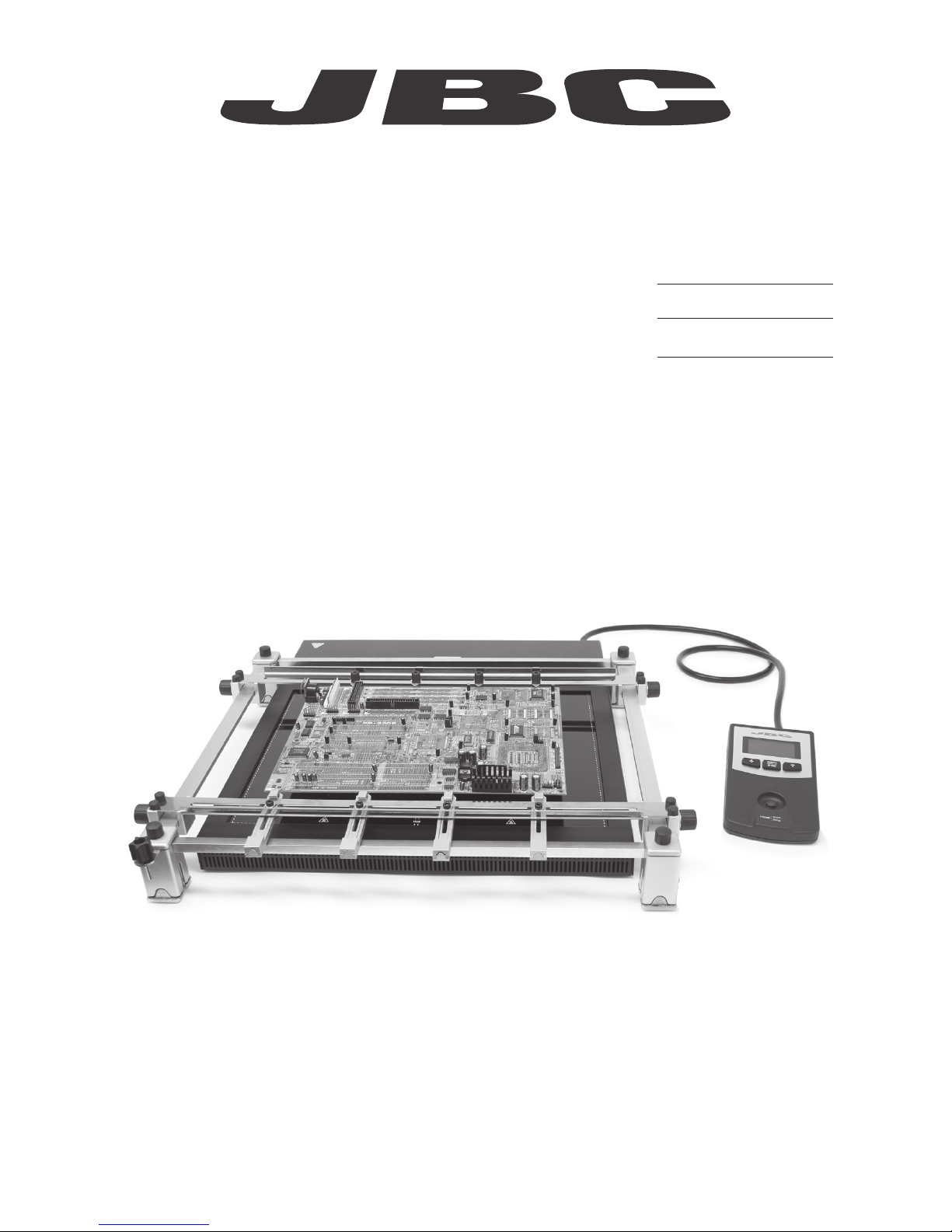
Convection Preheater Set
Ref. PHB-KA
English 2
Page
INSTRUCTION MANUAL
www.jbctools.com
Page 2
2
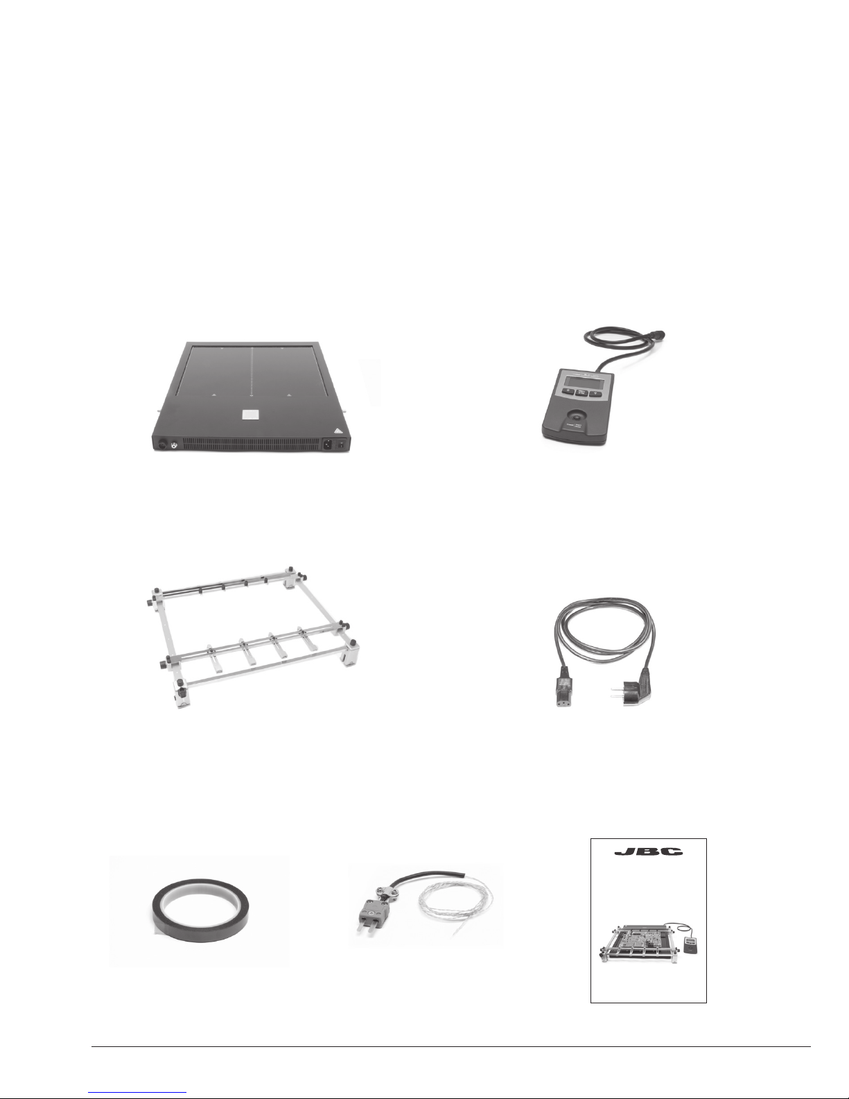
Packing List
The following items should be included:
Heater Unit Console
Power Cord .............................................. 1 unit
Ref. 0009417 (100V/120V)
0009401 (230V)
Thermocouple .............. 1 unit
Ref. PH218
Kapton Tape .................. 1 unit
Ref. PH217
Manual ............................ 1 unit
Ref. 0016815
Ref. PHB-KA
Convection Preheater Set
Convection Preheater ............................................................................................................................. 1 unit
Ref. PHB-1A (120V)
PHB-2A (230V)
PHB-9A (100V)
Convection Preheater Support ........... 1 unit
Ref. PHB-SA
INSTRUCTION MANUAL
www.jbctools.com
Page 3

3
Features
Pedal socket (optional)
Ref. P-005
Heating Areas
Power socket
Power
Fixing brackets
for PHB-SA
Convection Preheater
Support
Heater Unit
Console
Control Unit Start / Stop
Auxiliary Thermocouple (Type K) Input
Thermocouple
(Type K)
Ref. PH218
USB-B
connector to PC:
Update software
Zone A
Zone B
www.jbctools.com
Page 4
4
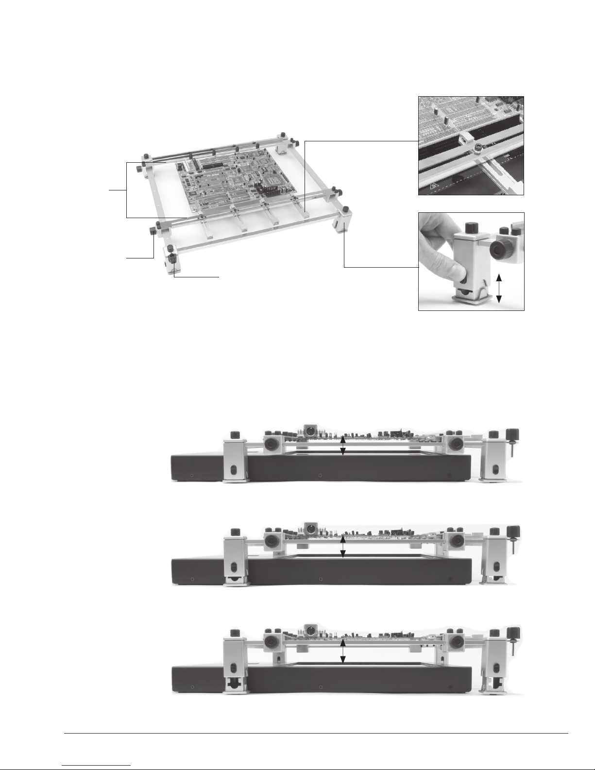
Height Adjustment
It allows adjustment for 3 heights between the PCB and the Heating Area of the PHB-A Heater Unit.
Low level
High level
Medium level
28 mm
38 mm
48 mm
PHB-SA Features
Adjustable slot clamps
for switching PCBs
Adjusting system
for changing height
Clamp knobs
Sliding
guides
Allen key
Page 5
5
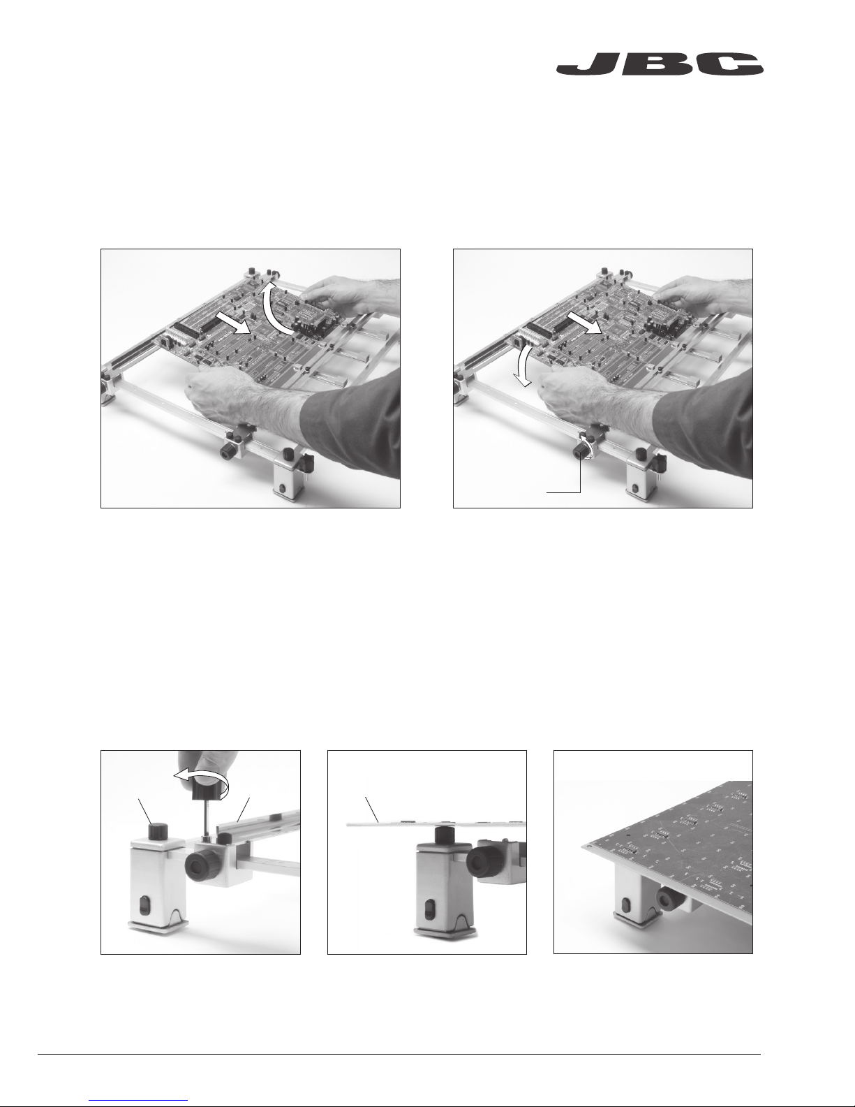
Changing PCBs of the same batch
Loosen one sliding guide, pull back and lift
out the PCB.
The support lets you place PCBs of the same batch so as to always heat the same area.
Use the sliding guides to change the PCBs.
Position it and tighten the sliding guide knobs.
Removing the PCB
Placing another PCB
Cap
Guide
PCB
Use the 4 caps to place larger PCBs than the PHB-SA Support or over 3mm thick.
1. Remove both guides by
untightening the 8 screws.
2. Place the PCB on the 4
rubber caps.
3. The PCB is ready to work.
Reworking large PCBs
Clamp knobs
www.jbctools.com
Page 6
6
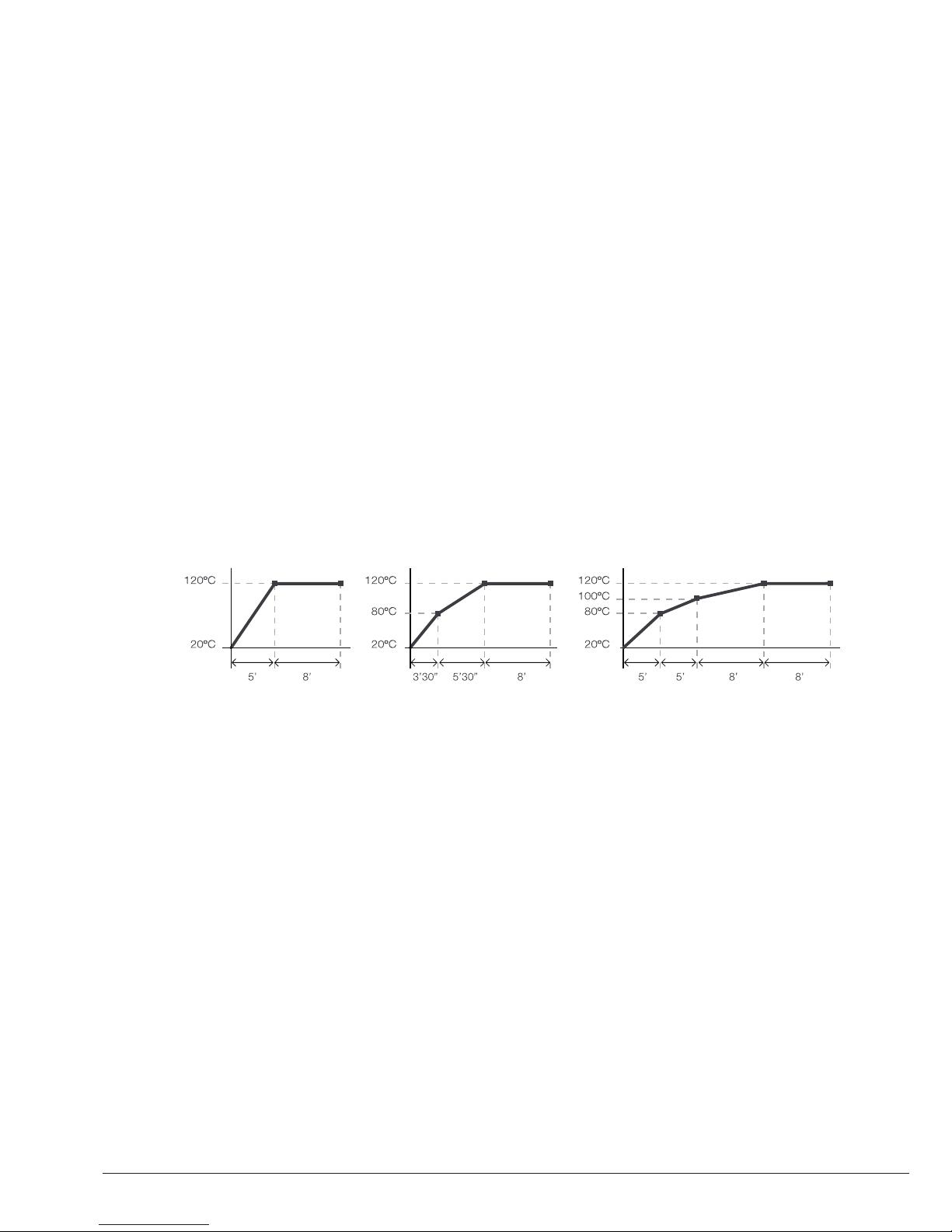
Profiles by Temperature
The usual way to run a profile is using the Thermocouple (TC) connected to the Control Input of the
console. JBC offers 3 predefined profiles (JBCset) and 20 profiles ready for you to personalize.
Why convection? Perfect heat distribution
Convection technology offers a uniform heat distribution over the whole working area of the
Preheater. This gradual heating system reduces the risk of thermal stress on the PCB.
Operation
JBCset profiles
There are 3 profiles predefined by JBC: A, B and C. The difference between them is the number
of steps: 2, 3 or 4. The thicker your PCB is and the more layers it contains, the more steps are
needed to obtain a gradual warming.
These profiles are not modifiable but they can be used as a template to create your own profiles.
JBCset A
2 steps
JBCset B
3 steps
JBCset C
4 steps
For repetitive jobs we recommend running profiles without the Thermocouple (TC). Once any
profile has been run to the end, the system has all the process data which you can save.
Once it is saved, you can run this profile without connecting the Thermocouple (TC). The heating
process will the same as long as the same working conditions are respected.
User profiles
You can create your own profiles from the JBCset profiles. On the work screen of the profile,
press the Enter button and choose the option Edit profile.
Power or Temperature Modes
The unit works at the selected power or temperature during the defined time. These parameters can
be modified from the work screen by pressing the Enter button and the Edit parameters menu.
To see the current temperature you must plug the Thermocouple (TC) into the Control connector.
PCB reference
specifications:
FR4 1,6mm thick
and 2 layers.
FR4 2,2mm thick
and 6 layers.
FR4 1,6mm thick
and 6 layers.
Profiles set using the low position of the PHB-SA Support (28 mm in height between the PCB and the heating area).
Page 7
7
Recommended Guidelines
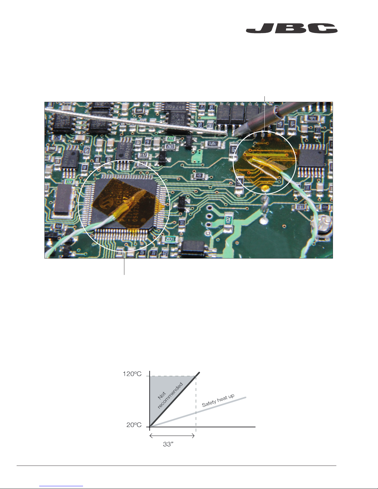
1. Place the Thermocouple (TC) as near as possible to the component being worked on.
2. If there are any sensitive components, use the Auxiliary Thermocouple as protection.
You can select the protection temperature in Station settings. If the selected temperature is
reached, the Heater Unit will stop the process and a warning message will be shown.
3. IPC* does not recommend exceeding ramp-up rates over 3 - 4 °C / sec (5 - 7 °F / sec) so as to
reduce the risk of thermal stress on the PCB.
* IPC was founded in the U.S. in 1957 as the Institute for Printed Circuits and is committed to becoming the
most recognized international industry association for the electronics manufacturing industry.
Fix the TC with Kapton Tape
Auxiliary Thermocouple (TC)
www.jbctools.com
Page 8
8
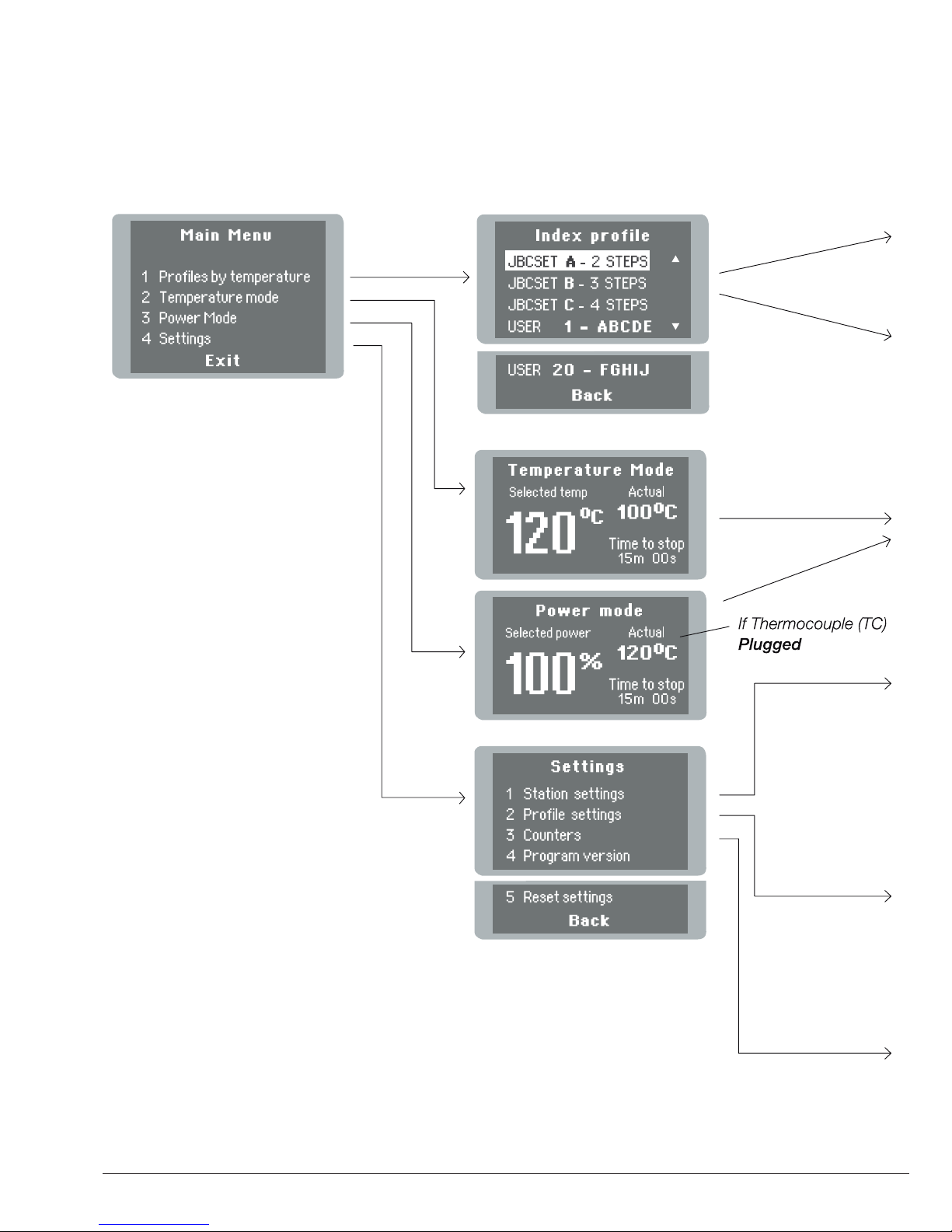
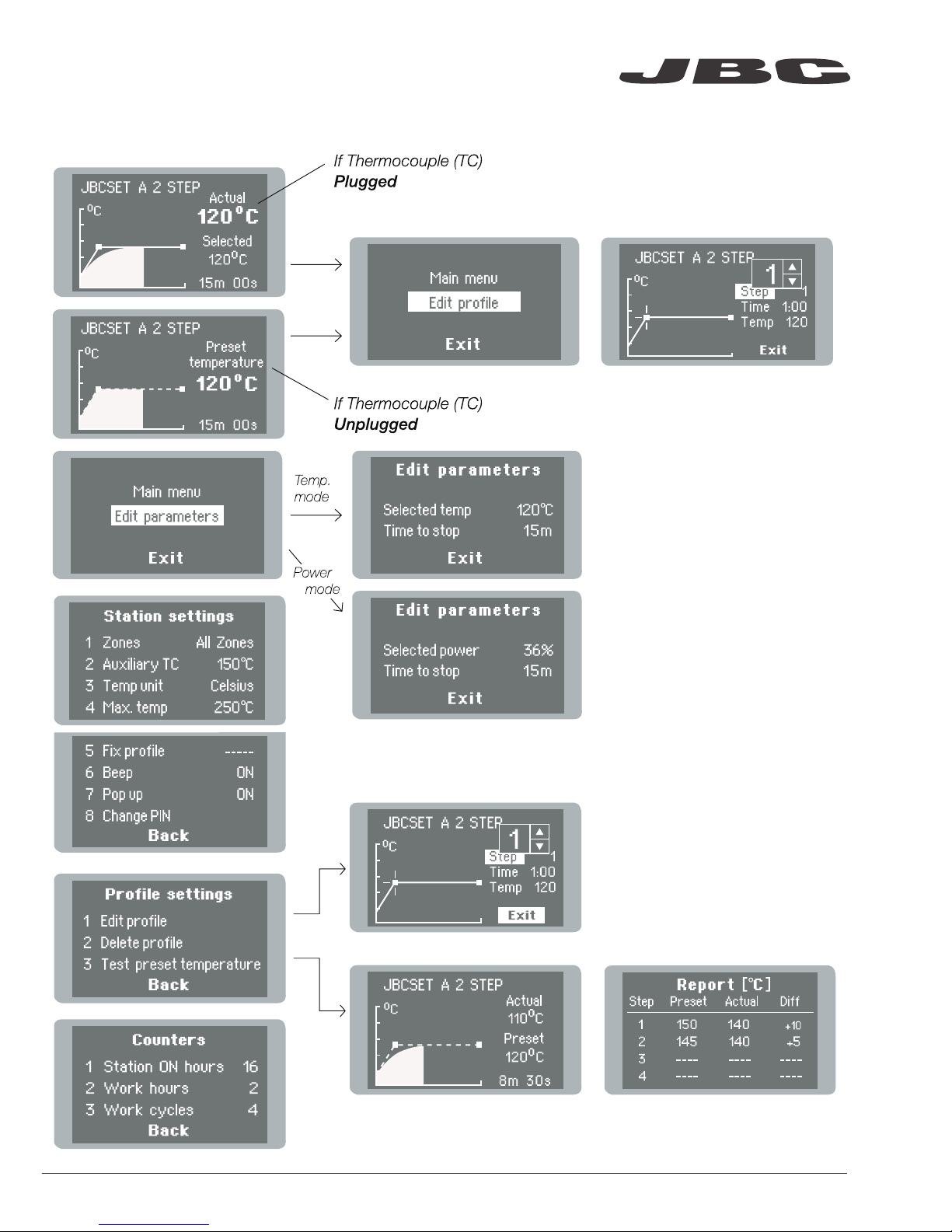
Display Control
Page 9
9
www.jbctools.com
Page 10

10
Maintenance
Before carrying out maintenance or storage, always allow the equipment and the support to cool.
- Check periodically that the PHB-KA is clean.
- Use a damp cloth when cleaning. Alcohol
can only be used to clean the metal parts.
- Only if it is absolutely necessary and
if cleaning with isopropyl alcohol (IPA) is not
enoug h, it is recomme nded to use a scrap er
to remove dirt in the glass area.
- Replace any defective or damaged parts.
Use original JBC spare parts only.
- Repairs should only be performed by a JBC
authorized technical service.
Clean periodically
Page 11

11
Safety
It is imperative to follow safety guidelines to protect health and prevent electric
shock, injury, fire or explosions.
- Do not use the units for any purpose other than PCB preheating. Incorrect use may cause fire.
- The mains cable must be plugged into approved bases. Make sure that it is properly grounded
before use. When unplugging it, hold the plug, not the wire.
- The temperature of accessible surfaces may remain high after the unit is turned off. Handle with care.
- Do not leave the appliance unattended when it is on.
- Do not cover the ventilation grills. Heat can cause inflamable products to ignite.
- Heat can cause inflamable products to ignite even when out of sight.
- Be careful with the remains of liquid tin. In contact with skin, it can cause burns.
- Avoid flux coming into contact with skin or eyes to prevent irritation.
- Be careful with the smoke produced when soldering.
- Keep your workplace clean and tidy. Wear appropriate protection glasses and gloves when
working to avoid personal harm.
- This appliance can be used by children over the age of eight as well as persons with reduced
physical, sensory or mental capabilities or lacking experience provided that they have been given
adequate supervision or instruction concerning use of the appliance and understand the hazards
involved. Children must not play with the appliance.
- Maintenance must not be carried out by children unless supervised.
www.jbctools.com
Page 12

12
Specifications
Convection Preheater Set
PHB-1KA / PHB-2KA / PHB-9KA
- Total weight: 9,8 kg (21.6 lb)
- Ambient operating temperature: 10 - 40 ºC (50 - 104 ºF)
PHB-1A 120V. Input 120V 50/60Hz Fuse 15A
PHB-2A 230V. Input 230V 50/60Hz Fuse 10A
PHB-9A 100V. Input 100V 50/60Hz Fuse 15A
- Weight: 7 kg (15.4 lb)
- Dimensions (Heater Unit): 426 x 446 x 41 mm (16.7 x 17.6 x 1.6 in)
- Maximum Power: 1800W / 1800W / 1400W
- Heating Area: 180 x 277 mm (7.1 x 10.9 in - 1 zone)
360 x 277 mm (14.2 x 10.9 in - 2 zones)
- Temperature Range: 50 - 250 °C (120 - 482 ºF)
- Temperature Measurement: Thermocouple type K
- JBCset temperature profiles: 3 profiles (2, 3 or 4 steps)
- User Profiles: 20 (up to 6 steps for each)
- Maximum work time: 600 min or indefinite
PHB-SA
- Weight: 2,8 kg (6.2 lb)
- Dimensions (Low Position): 432 x 514 x 78 mm (17 x 20.2 x 3.1 in)
- Dimensions (High Position): 432 x 514 x 98 mm (17 x 20.2 x 3.9 in)
- Maximum thickness of PCB: 6 mm
Complies with CE standards.
ESD protected housing.
Page 13

Set Precalentador
de Convección
Ref. PHB-KA
13
www.jbctools.com
Page 14

Composición
Los siguientes artículos deberían estar incluidos:
Power Cord
Cable de red ......................................... 1 unidad
Ref. 0009417 (100V/120V)
0009401 (230V)
Convection Preheater Support
Soporte para Precalentador PHB ..... 1 unidad
Ref. PHB-SA
Thermocouple
Termo par (Tipo K) .... 1 unidad
Ref. PH218
Kapton Tape
Cinta Kapton ............ 1 unidad
Ref. PH217
Manual ...................... 1 unidad
Ref. 0016815
Convection Preheater Precalentador ............................................................................................ 1 unidad
Ref. PHB-1A (120V)
PHB-2A (230V)
PHB-9A (100V)
Heater Unit
Unidad calefactora
Console
Consola
14
Ref. PHB-KA
Convection Preheater Set
www.jbctools.com
Page 15

Zona A
Zona B
Características
Conector de Pedal (opcional)
Ref. P-005
Áreas calefactoras
Toma de Red
Interruptor general
Fijadores para el
soporte PHB-SA
Unidad de Control Botón Inicio / paro
Conector para Termopar auxiliar (Tipo K)
Termopar
(Tipo K)
Ref. PH218
Conector USB-B a PC:
Actualice el software
Heater Unit
Unidad calefactora
Console
Consola
15
www.jbctools.com
Page 16

16
Ajuste de altura
El soporte PHB-SA permite ajustar 3 alturas entre el PCB y el área calefactora.
Nivel Bajo
Nivel Alto
Nivel Medio
28 mm
38 mm
48 mm
PHB-SA Características
Abrazaderas ajustables
para intercambiar PCBs
Sistema de ajuste
de alturas
Pomos de
apriete
Guías
deslizantes
Llave Allen
Page 17

17
Intercambiar PCBs de un mismo lote
Afloje una de las guías deslizantes mediante
sus pomos de apriete, tire hacia usted y retire
el PCB.
El soporte permite colocar PCBs de un mismo lote de manera que siempre se caliente la misma zona.
Utilice las abrazaderas ajustables para intercambiar los PCBs manteniendo fija la guia deslizante.
Posicione el nuevo PCB y vuelva a fijar la guía.
Retirar el PCB
Colocar el nuevo PCB
Tapón
Guía
PCB
Utilice los cuatro tapones para colocar PCBs de unas dimensiones superiores al soporte o que tengan
un espesor por encima de los 3 mm
1. Retire ambas guías
desenroscando los tornillos.
2. Coloque el PCB encima de
los 4 tapones.
3. El PCB está listo para
trabajar.
Reparar PCBs de mayor tamaño
Pomos de
apriete
www.jbctools.com
Page 18

Perfiles por Temperatura
El modo usual de ejecutar un perfil es utilizando el Termopar (TC) en el conector de Control.
JBC le ofrece 3 perfiles predefinidos (JBCset) y 20 perfiles listos para personalizar (User Profiles).
Funcionamiento
JBCset A
2 pasos
JBCset B
3 pasos
JBCset C
4 pasos
Recomendamos que para trabajos repetitivos, se ejecuten los perfiles sin Termopar: Una vez un
perfil cualquiera se ha ejecutado hasta el final, el sistema dispone de todos los datos del proceso
y pregunta si se desea salvar. En caso afirmativo se podrá ejecutar ese perfil sin tener el termopar
conectado. El proceso de calentamiento será idéntico siempre que se respeten las mismas
condiciones de trabajo.
Perfiles JBCset (JBCset profiles)
Hay 3 perfiles predefinidos por JBC: A, B y C. La diferencia entre ellos es el número de pasos:
2, 3 o 4. Cuanto más grueso sea su PCB y más capas contenga, más pasos serán necesarios
para obtener un calentamiento uniforme y progresivo.
Estos perfiles no son modificables pero pueden ser usados como plantilla para crear sus
propios perfiles (User Profiles).
Perfiles de Usuario
Puede crear sus propios perfiles a partir de los perfiles JBCset. Desde la pantalla de trabajo del
perfil, apriete el botón Enter y elija la opción Edit profile.
PCBs y
condiciones
de referencia:
FR4 de espesor
1,6mm y 2 capas.
FR4 de espesor
2,2mm y 6 capas.
FR4 de espesor
1,6mm y 6 capas.
Por qué convección? Perfecta distribución del calor
La tecnología de convección ofrece una distribución uniforme del calor en toda la zona de trabajo.
Su sistema de calentamiento gradual reduce el riesgo de estrés térmico.
Modos de Temperatura o potencia
La unidad funciona a la potencia o temperatura seleccionada durante el tiempo establecido.
Estos parámetros pueden ser modificados desde la pantalla de trabajo apretando el botón Enter y
accediendo al menu Edit parameters.
Si desea ver la temperatura actual debe conectar el Termopar en el conector de Control.
Perfiles realizados utilizando la posición baja del soporte PHB-SA (28 mm de altura entre el PCB y el área calefactora).
18
Page 19

Recomendaciones
Cinta Kapton para fijar el Termopar en el PCB
1. Coloque el Termopar tan cerca como sea posible del componente a trabajar.
2. Si hay algún componente sensible, use el Termopar Auxiliar como protección.
Puede seleccionar la temperatura de protección en el menú Station settings. Si la temperatura
llega a la establecida, se interrumpirá el proceso y mostrará un warning.
3. IPC* no recomienda exceder tasas de rampas por encima de los 3 - 4 °C / seg (5 - 7 °F / seg)
con el fin de reducir el riesgo de estrés térmico en los PCBs.
* IPC se fundó en USA en 1957 con el nombre de Institute for Printed Circuits con la intención de convertirse en
la asociación internacional más reconocida de la industria manufacturera electrónica.
Termopar Auxiliar (TC)
19
www.jbctools.com
Page 20

Pantallas de control
20
Page 21

21
www.jbctools.com
Page 22

Mantenimiento
Antes de almacenar o de su mantenimiento, desconecte el equipo y déjelo enfriar.
- Compruebe periódicamente que el set
PHB-KA esté limpio.
- Utilice un paño húmedo para limpiar. Sólo
utilice alcohol para las partes metálicas.
- Solo cuando sea absolutamente necesario
y si la limpieza con isopropanol (IPA) no es
suficiente, se ecomienda el uso de una
rasqueta para limpiar la suciedad adherida en
la zona del cristal.
- Cambie cualquier pieza defectuosa o dañada.
Utilice solamente recambios originales de JBC.
- Cualquier reparación sólo podría ser realizada
por un servicio técnico oficial JBC.
Limpie periódicamente
22
Page 23

Seguridad
- No utilice la unidad para otros fines que no sea el precalentamiento de PCBs. El uso incorrecto
puede causar fuego.
- El cable de red debe enchufarse en bases homologadas. Asegúrese de que está conectado a
tierra antes correctamente antes de su uso. Al desenchufarlo, tire del conector, no del cable.
- La temperatura de las superficies accesibles puede ser alta incluso cuando la unidad está
apagada. Manipule con cuidado.
- No deje el aparato desatendido cuando esté en funcionamiento.
- No cubra las rejillas de ventilación. El calor puede causar que los productos inflamables se enciendan.
- El calor puede causar que los productos inflamables se enciendan aunque no estén a la vista.
- Tenga cuidado con los restos de estaño líquido. En contacto con la piel, puede causar
quemaduras.
- Evite el contacto del Flux con la piel o los ojos para prevenir la irritación.
- Tenga cuidado con el humo producido al trabajar.
- Mantenga su lugar de trabajo limpio y ordenado. Use gafas y guantes de protección adecuados.
Así evitará cualquier daño.
- Este aparato puede ser utilizado por personas a partir de 8 años y también por aquellas
personas con movilidad reducida o capacidades físicas, sensoriales o mentales limitadas o
con falta de experiencia y conocimientos siempre y cuando reciban supervisión o instrucciones
relativas al uso del aparato de una manera segura y entiendan los riesgos que implica. Los niños
no deben jugar con el aparato.
- Los niños no deberán realizar tareas de mantenimiento sin supervisión.
Es necesario seguir estas directrices de seguridad para proteger su salud y
prevenir cualquier choque eléctrico, heridas, fuego o explosiones.
23
www.jbctools.com
Page 24

Especificaciones técnicas
Convection Preheater Set · Set Precalentador de Convección
PHB-1KA / PHB-2KA / PHB-9KA
- Peso total: 9,8 kg (21.6 lb)
- Temperatura de trabajo ambiente: 10 - 40 ºC (50 - 104 ºF)
PHB-1A 120V. Entrada 120V 50/60Hz Fusible 15A
PHB-2A 230V. Entrada 230V 50/60Hz Fusible 10A
PHB-9A 100V. Entrada 100V 50/60Hz Fusible 15A
- Peso: 7 kg (15.4 lb)
- Dimensiones (Unidad calefactora): 426 x 446 x 41 mm (16.7 x 17.6 x 1.6 in)
- Potencia máxima: 1800W / 1800W / 1400W
- Área calefactora: 180 x 277 mm (7.1 x 10.9 in - 1 zona)
360 x 277 mm (14.2 x 10.9 in - 2 zonas)
- Rango de temperatura: 50 - 250 °C (120 - 482 ºF)
- Medición de temperatura: Termopar Tipo K
- Perfiles predefinidos por JBC (JBCset): 3 perfiles (2, 3 or 4 pasos)
- Perfiles de usuario: 20 (hasta 6 pasos para cada uno)
- Tiempo de trabajo máximo: 600 min o indefinido
PHB-SA
- Peso: 2,8 kg (6.2 lb)
- Dimensiones (Nivel Bajo): 432 x 514 x 78 mm (17 x 20.2 x 3.1 in)
- Dimensiones (Nivel Alto): 432 x 514 x 98 mm (17 x 20.2 x 3.9 in)
- Grueso máximo de PCB: 6 mm
Cumple con las normativas CE.
Protección ESD.
24
Page 25

25
Notes
www.jbctools.com
Page 26

26
Exploded View · Despiece
Page 27

27
www.jbctools.com
Page 28

Garantía
Esta garantía de 2 años cubre este equipo contra cualquier defecto de fabricación, incluyendo la sustitución
de partes defectuosas y mano de obra. La garantía no cubre el desgaste del producto por uso o mal uso. Para
que esta garantía sea válida, el equipo debe ser devuelto, a portes pagados, al distribuidor donde se compró.
Registre la garantía de su producto dentro de los 30 días de la compra en www.jbctools.com/productregistration.
Este producto no debe desecharse en la basura.
De acuerdo a la directiva europea 2012/19/UE, los equipos electrónicos al final de su vida se deberán
recoger y trasladar a una planta de reciclaje autorizada.
0016815-0817
Warranty
JBC’s 2 year warranty covers this equipment against all manufacturing defects, including the replacement of
defective parts and labour. Warranty does not cover product wear or misuse. In order for the warranty to be valid,
equipment must be returned, postage paid, to the dealer where it was purchased. Please register your warranty
within 30 days of purchase in www.jbctools.com/productregistration.
This product should not be thrown in the garbage.
In accordance with the European directive 2012/19/EU, electronic equipment at the end of their life
must be collected and returned to an authorized recycling facility.
www.jbctools.com
 Loading...