

Page 1
www.jbctools.com
INSTRUCTION MANUAL
Convection Preheater Set
Ref. PHBE-KA
Page 2
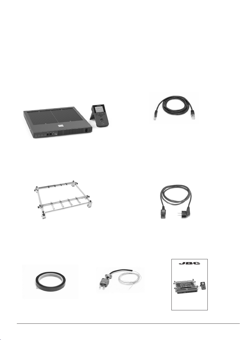
Packing List
The following items should be included:
Convection Preheater ............................ 1 u ni t
Ref. PHBE-1A (120V)
PHBE-2A (230V)
PHBE-9A (100V)
Heater Unit
Console
Convection Preheater Support ........... 1 unit
Ref. PHB-SA
RJ45 Cable ................................................ 1 unit
Re f. 0 019914
Power Cord ............................................... 1 unit
Ref. 0016814 (100V/120V)
0009401 (230V)
Kapton Tape .................. 1 unit
Ref. PH217
2
Thermocouple .............. 1 u ni t
Ref. PH218
Manual ............................ 1 unit
Ref . 0023 517
www.jbctools.com
Convection Preheater Set
Ref. PHBE-KA
Page 3
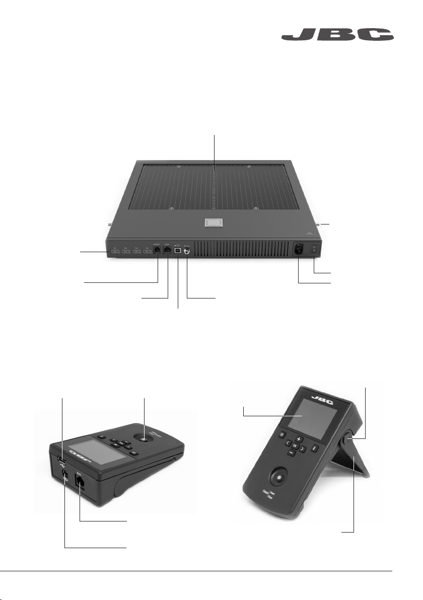
Features
Heater Unit
www.jbctools.com
Heating Areas
Thermocouple
connectors x4
RJ12 connector
to Robot
Console
USB-A connector
RJ45 connector
to Console
Start / Stop
Zone A
USB-B connector
Zone B
Fixing brackets
for PHB-SA
Convection
Preheater Support
Power
Power socket
Pedal socket (optional)
Ref. P-005 or P-405
Push the button
to fold the foot
2,8” Color
TFT screen
RJ45 connector
to Heater Unit
USB-B connector
Foot for ver tical set up
3
Page 4
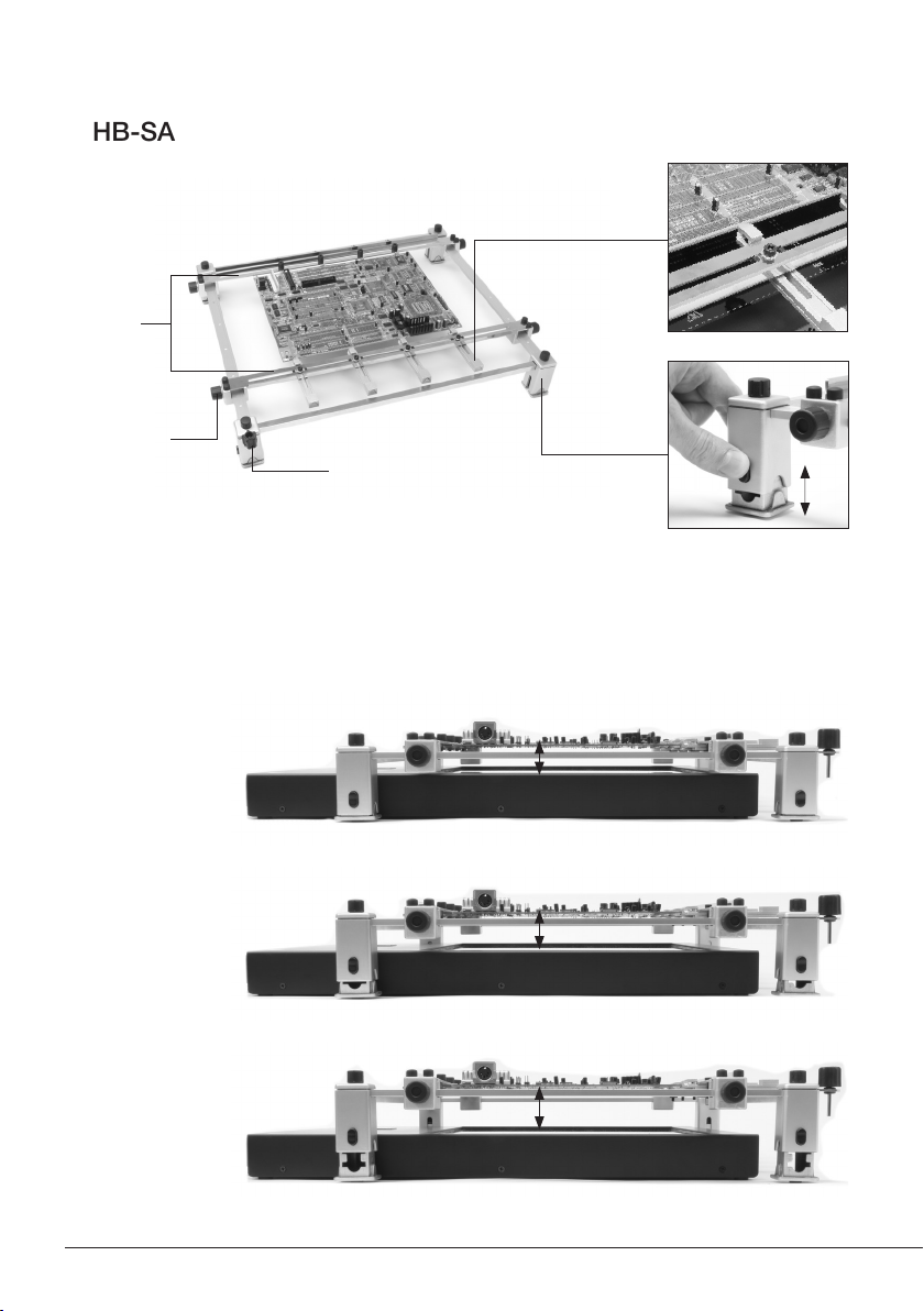
PHB-SA Features
Adjustable slot clamps
for switching PCBs
Sliding
guides
Clamp knobs
Allen key
Adjusting system
for changing height
Height Adjustment
It allows adjustment for 3 heights between the PCB and the Heating Area of the PHBE-A Heater
Unit.
Low level
28 mm
Medium level
38 mm
High level
48 mm
4
Page 5
www.jbctools.com
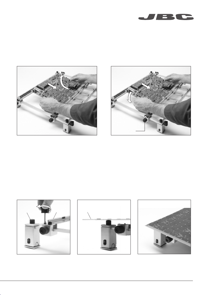
Changing PCBs of the same batch
The support lets you place PCBs of the same batch so as to always heat the same area.
Use the sliding guides to change the PCBs.
Removing the PCB
Loosen one sliding guide, pull back and lift
out the PCB.
Clamp knobs
Position it and tighten the sliding guide knobs.
Placing another PCB
Reworking large PCBs
Use the 4 caps to place larger PCBs than the PHB-SA Support or over 3mm thick.
Cap
1. Remove both guides by
untightening the 8 screws.
Guide
PCB
2. Place the PCB on the 4
rubber caps.
3. The PCB is ready to work.
5
Page 6

Temperature mode
Select Temp. mode from the Work mode menu. In this mode the heater unit maintains the selected
temperature for the TC1 thermocouple as long as the other TCs do not reach the control/protection
temperature limit.
Status bar
Instant power
supplied to
heater
TC2
Thermocouple
current temp.
Thermocouple
selected temp.
and mode
· Control
· Protection
· Info
Power
45%
C
P
20
100
P
º
Menu Options
Press INFO for each parameter description.
General Work mode Profile editor
TC1
45
Selected 150ºC
C
º
C
14:15
º
C
TC3
20
100
P
º
C
º
C
TC4
20
100
P
º
C
º
C
*Original PIN: 0105
System notifications (Status Bar)
USB flash drive is connected.
Station is controlled by a PC.
Station is controlled by a robot.
Status
indicator
TC1 current
and selected
Temperature
Station
Information
ResetGraphics Files
Available languages: English, Spanish,
German, French, Italian, Portuguese,
Japanese, Chinese, Russian and Korean.
6
Station sof tware update.
Press INFO to start the process.
Warning.
Press INFO for failure description.
Error. Press INFO for failure description,
the type of error and how to proceed.
Page 7

www.jbctools.com
Power mode
Select Power mode from the Work mode menu. In this mode the heater unit maintains the selected
power as long as the thermocouples do not reach the control/protection temperature limit.
Status bar
Instant power
supplied to
heater
Thermocouple
current temp.
Power
45%
Selected power
TC1
º
C
20
º
100
C
P
45
TC2
º
20
º
100
P
Thermocouple
selected temp.
and mode
· Control
· Protection
· Info
14:15
%
TC3
C
20
C
P
100
TC4
º
C
º
C
C
P
20
P
100
º
C
º
C
Thermocouples
Select Thermocouples from the Work mode menu to set them up.
The thermocouples (TC) can work in three diferent ways depending on what is needed.
· Control: the unit mantains the selected temperature.
Status
indicator
Selected
Power
· Protection: the Heater Unit stops if the TC reaches the selected temperature.
· Info: the TC temperature is shown in the work screen.
The TC1 is always working in Control mode for the Temperature mode as well as for Profiles mode.
The temperature of each TC can also be selected from the work screen.
7
Page 8

Profiles mode
Select Profile mode from the Work mode menu. In this mode the heater unit regulates the
temperature of the TC1 thermocouple according to the selected profile as long as the other TCs do
not reach the control/protection temperature limit.
14:15
PROFILE1
200
100
TC1
20
º
TC2
C
20
TC3
º
C
20
Stop
TC4
º
C
20
º
C
Teach profile
For repetitive jobs we recommend running profiles without the Thermocouple (TC). In order to do
so, the Teach profile mode has to be executed before running any profile. It can be executed from
the Work mode menu if the Profiles mode is selected. Once the profile has been run to the end, the
system has all the process data which you can save.
Once it is saved, you can run this profile without connecting the Thermocouple (TC). The heating
process will be the same as long as the same working conditions are respected.
The profiles which already have the data from the Teach profile are marked with this symbol
These profiles can be run either with or without the Thermocouples. It can be chosen from the
Profiles mode work screen:
8
Page 9

www.jbctools.com
Profile editor
The Profile editor can be opened from the main menu or from the Profiles mode work
screen by pressing the ‘OK’ button.
In this mode you can edit as many as 22 profiles of temperature.
Profile
editor
14:15
Profile name
Data for
these points
PROFILE1
200
100
0 60 120 180 240 300
Point
2/4
Temp Time
º
C
150
5m 00s
2m 00s
JBC set profiles
There are 3 profiles predefined by JBC: A, B and C. The difference between them is the number of
steps: 2, 3 or 4. The thicker your PCB is and the more layers it contains, the more steps are needed
to obtain a gradual warming.
These profiles are not modifiable but can be used as a template to create your own profiles.
Menu
Options
· Add point
· Delete point
· Load profile
· Save profile
· Exit
JBC-A
2 steps
PCB reference
specifications:
Profiles set using the low position of the PHS-SA Support (28 mm in height between the PCB and the heating area).
FR4 1,6mm thick
and 2 layer s.
JBC-B
3 steps
FR4 1,6mm thick
and 6 layer s.
JBC-C
4 steps
FR4 2,2mm thick
and 6 layer s.
9
Page 10

Process analysis
By pressing Graphics in the main MENU, temperature of TC1 thermocouple and power
figures in real time are displayed.
Graphics
Power (%)
Temperature
17:14
300
250
200
150
100
50
10
Powe r[%]
Ext.Temp[ºC]
Switch Y a xis
between power
and temperature
Page 11

Files
Export graphics
Insert a USB flash drive into the USB-A
connector to save your soldering
process in csv format.
Files
Export / Import profiles
Insert a USB flash drive into
the USB-A connector to
export / import profiles.
Update the station software
www.jbctools.com
1. Download the JBC Update File from
www.jbctools.com/software.html and save
it on a USB flash drive. (Preferably one with no
other files).
JBC
Update File
2. Insert the USB flash drive to the station.
The icon is diplayed while updating.
11
Page 12

Recommended Guidelines
1. Place the Thermocouple (TC) as near as possible to the component being worked on.
Fix the TC with Kapton Tape
Protection Thermocouple (TC)
2. If there are any sensitive components, use a Thermocouple as protection.
You can select the protection temperature in the Thermocouples menu. If the selected tempertare
is reached, the Heater Unit will stop the process and a warning message will be shown.
3. IPC* does not recommend exceeding ramp-up rates over 3 - 4 °C / sec (5 - 7 °F / sec) so as to
reduce the risk of thermal stress on the PCB.
* IPC was founded in the U.S. in 1957 as the Institute for Printed Circuits and is committed to becoming the
most recognized international industry association for the electronics manufacturing industry.
12
Page 13

www.jbctools.com
Maintenance
Before carrying out maintenance or storage, always allow the equipment and the support to cool.
- Check periodically that the PHBE-KA is
clean.
- Use a damp cloth when cleaning. Alcohol
can only be used to clean the metal parts.
- Only if it is absolutely necessary and
if cleaning with isopropyl alcohol (IPA) is not
enough, i t is recommen ded to use a scrape r
to remove dirt in the glass area.
- Replace any defective or damaged parts.
Use original JBC spare parts only.
- Repairs should only be performed by a JBC
authorized technical service.
Clean periodically
13
Page 14

Safety
It is imperative to follow safety guidelines to protect health and prevent electric
shock, injury, fire or explosions.
- Do not use the units for any purpose other than PCB preheating. Incorrect use may cause fire.
- The mains cable must be plugged into approved bases. Make sure that it is properly grounded
before use. When unplugging it, hold the plug, not the wire.
- The temperature of accessible surfaces may remain high after the unit is turned off. Handle with care.
- Do not leave the appliance unattended when it is on.
- Do not cover the ventilation grills. Heat can cause inflamable products to ignite.
- Heat can cause inflamable products to ignite even when out of sight.
- Be careful with the remains of liquid tin. In contact with skin, it can cause burns.
- Avoid flux coming into contact with skin or eyes to prevent irritation.
- Be careful with the smoke produced when soldering.
- Keep your workplace clean and tidy. Wear appropriate protection glasses and gloves when
working to avoid personal harm.
- This appliance can be used by children over the age of eight as well as persons with reduced
physical, sensory or mental capabilities or lacking experience provided that they have been given
adequate supervision or instruction concerning use of the appliance and understand the hazards
involved. Children must not play with the appliance.
- Maintenance must not be carried out by children unless supervised.
14
Page 15

Specifications
Convection Preheater Set
PHBE -1K A / PHBE-2KA / PHBE-9KA
- Total weight: 9,7 kg (21.6 lb)
- Ambient operating temperature: 10 - 40 ºC (50 - 104 ºF)
PHBE-1A 120V. Input 120V 50/60Hz Fuse 15A
PHBE-2A 230V. Input 230V 50/60Hz Fuse 10A
PHBE-9A 100V. Input 100V 50/60Hz Fuse 15A
- Weight: 6,9 kg (15.4 lb)
- Dimensions (Heater Unit): 426 x 444 x 41 mm (16.8 x 17.5 x 1.6 in)
- Maximum Power: 1800W / 1800W / 1400W
- Heating Area: 180 x 277 mm (7.1 x 10.9 in - 1 zone)
360 x 277 mm (14.2 x 10.9 in - 2 zones)
- Temperature Range: 50 - 250 °C (120 - 482 ºF)
- Temperature Measurement: Thermocouple type K
- JBCset temperature profiles: 3 profiles (2, 3 or 4 steps)
- User Profiles: 22 (up to 6 steps for each)
- Maximum work time: 600 min or indefinite
PHB-SA
- Weight: 2,8 kg (6.2 lb)
- Dimensions (Low Position): 432 x 514 x 78 mm (17 x 20.2 x 3.1 in)
- Dimensions (High Position): 432 x 514 x 98 mm (17 x 20.2 x 3.9 in)
- Maximum thickness of PCB: 6 mm
www.jbctools.com
Complies with CE standards.
ESD protected housing.
15
Page 16

Warranty
JBC’s 2 year warranty covers this equipment against
all manufacturing defects, including the replacement
of defective parts and labour.
Warrant y does not cover product wear or misuse.
In order for the warranty to be valid, equipment must
be returned, postage paid, to the dealer where it was
purchased.
Get 1 extra year JBC warranty by registering here:
https://www.jbctools.com/productregistration/
within 3 0 days of purchase.
This product should not be thrown in the garbage.
In accordance with the European directive 2012/19/EU, electronic equipment at the end of its life must
be collected and returned to an authorized recycling facility.
www.jbctools.com
0023517-0519
 Loading...