

Page 1
中文 31
Deutsch 21
Español 11
IR Preheater
Ref. PHS-B
English 2
Page
www.jbctools.com
Page 2
Packing List
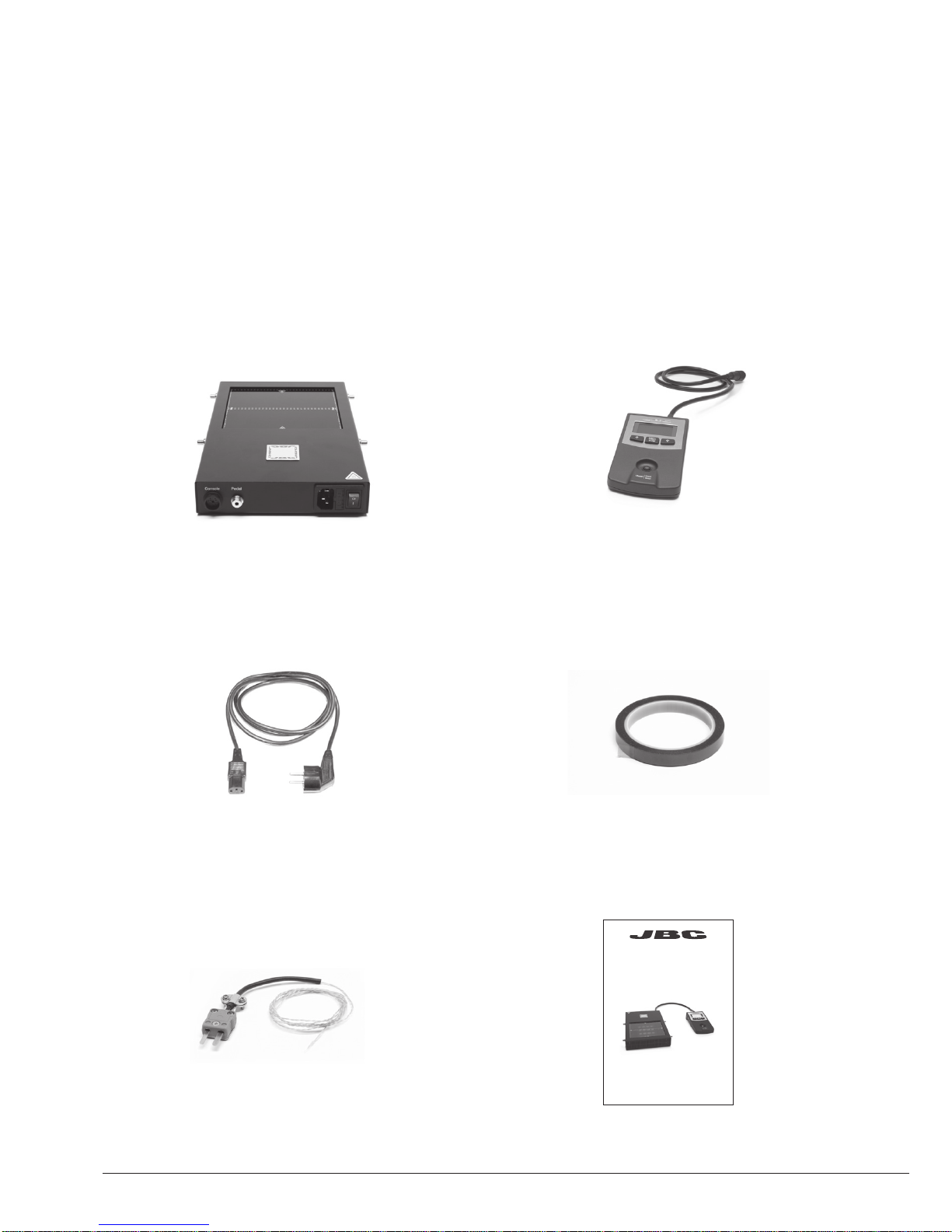
The following items should be included:
Heater Unit Console
Power Cord ................................................ 1 unit
Ref. 0009417 (100V/120V)
0009401 (230V)
Thermocouple .......................................... 1 unit
Ref. PH218
Kapton Tape .............................................. 1 unit
Ref. PH217
Manual ......................................................... 1 unit
Ref. 0017241
Ref. PHS-B
IR Preheater
IR Preheater ............................................................................................................................................... 1 unit
Ref. PHS-1B (120V)
PHS-2B (230V)
PHS-9B (100V)
2
www.jbctools.com
Page 3
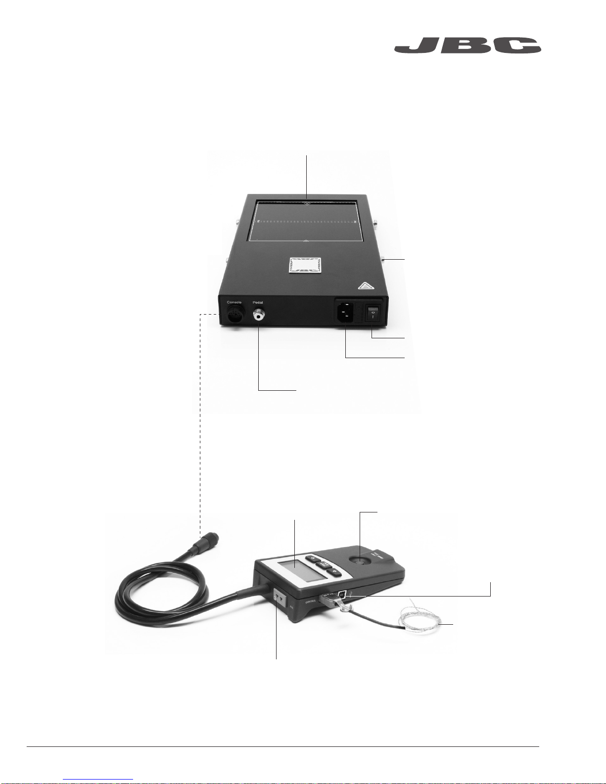
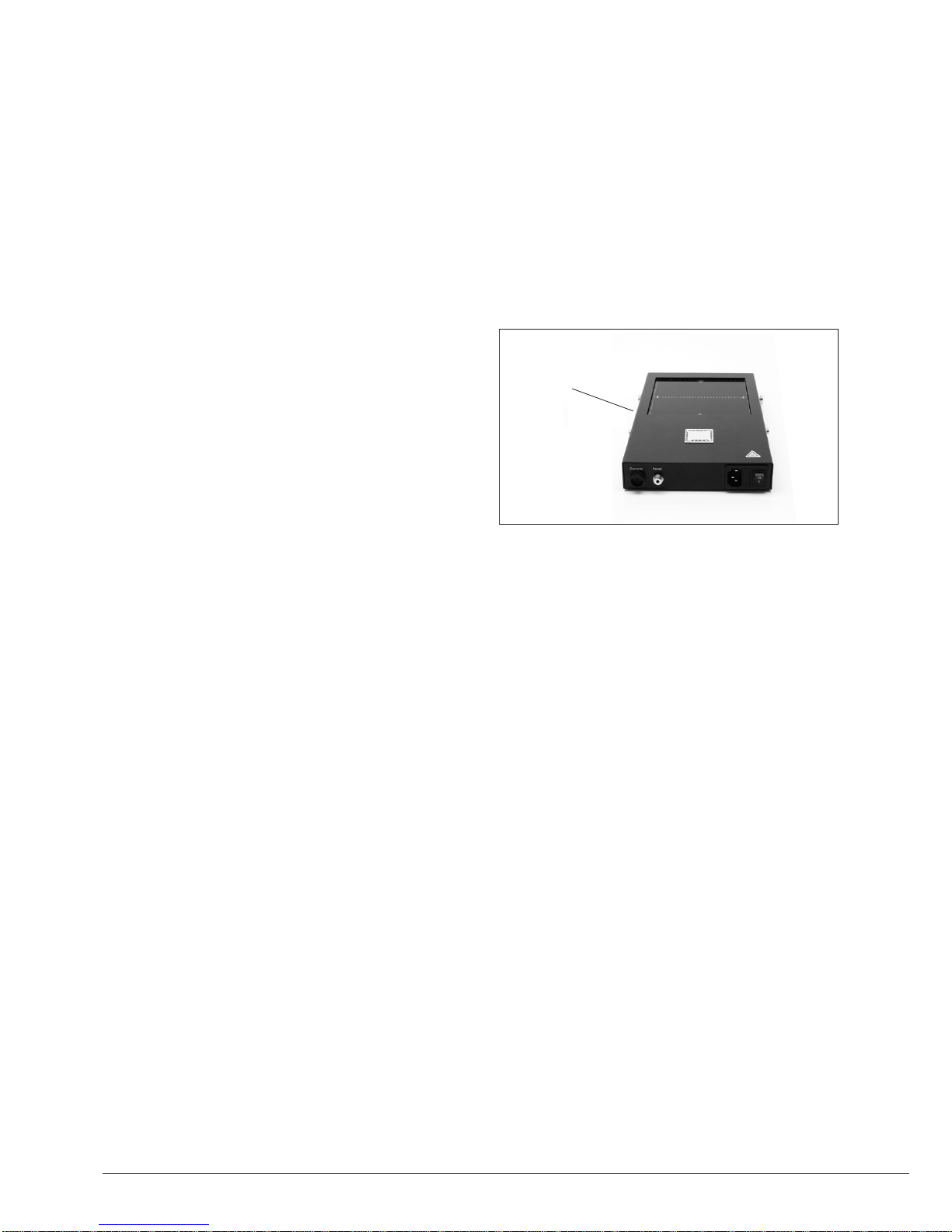
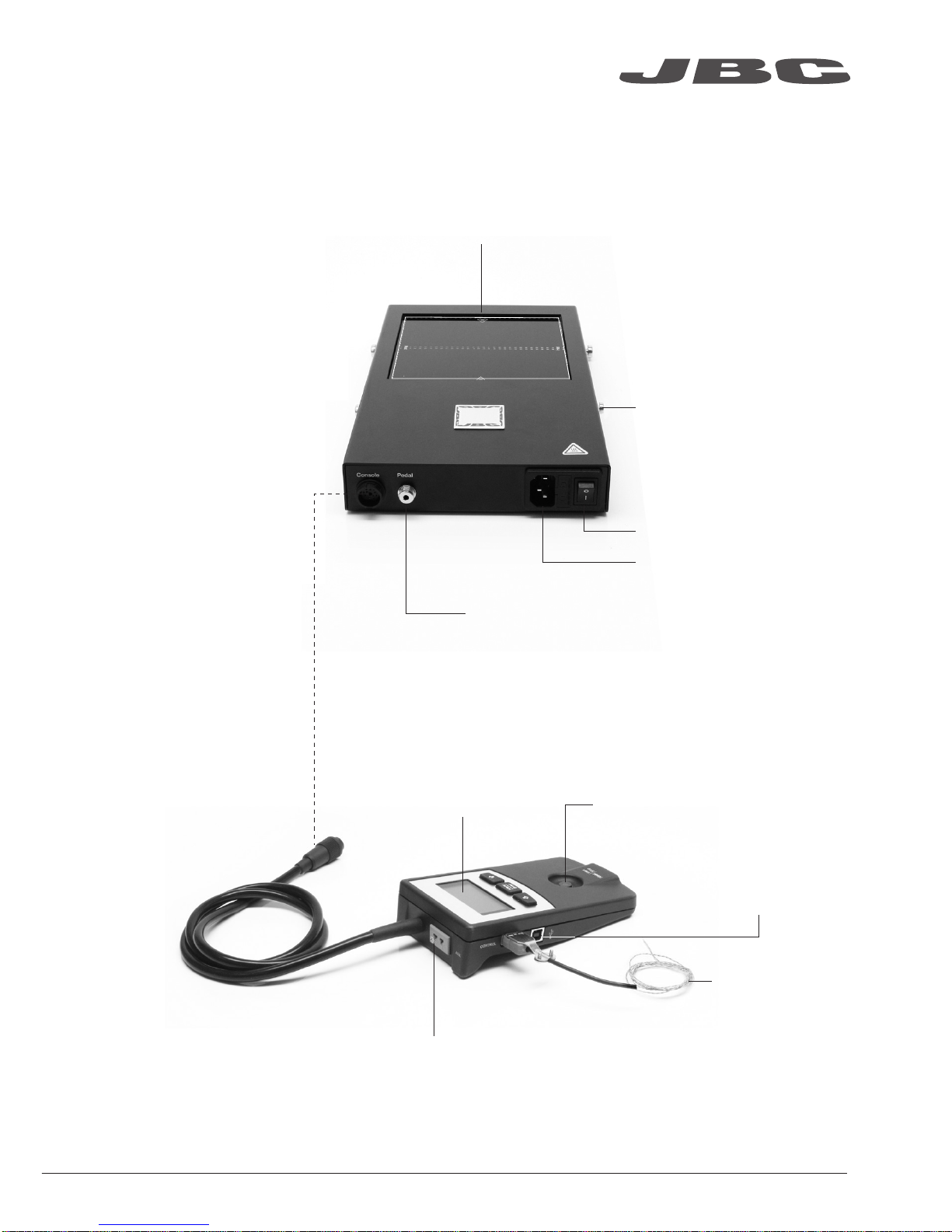
Features
Pedal socket (optional)
Ref. P-005
Heating Areas
Power socket
Power
Fixing brackets for
PHS-SA Convection
Preheater Support
Heater Unit
Console
Control Unit Start / Stop
Auxiliary Thermocouple (Type K) Input
Thermocouple
(Type K)
Ref. PH218
USB-B
connector to PC:
Update software
Zone A
Zone B
www.jbctools.com
3
Page 4

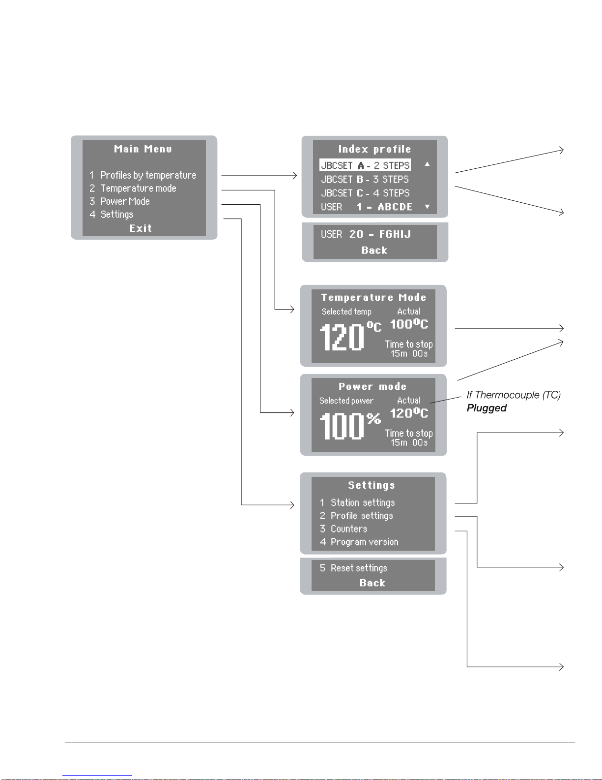
Profiles by Temperature
The usual way to run a profile is using the Thermocouple (TC) connected to the Control Input of the
console. JBC offers 3 predefined profiles (JBCset) and 10 profiles ready for you to personalize.
Why Infrared? The most efficient technology for PCB preheating
This is the most advanced, efficient and cost-effective method to preheat PCBs in any soldering job
or rework job. The low thermal mass of the infrared element gives outstanding control of the heat
output and the process temperature. This technology provides fast response, high heating rates and
uniform heating that ensure the best results.
Operation
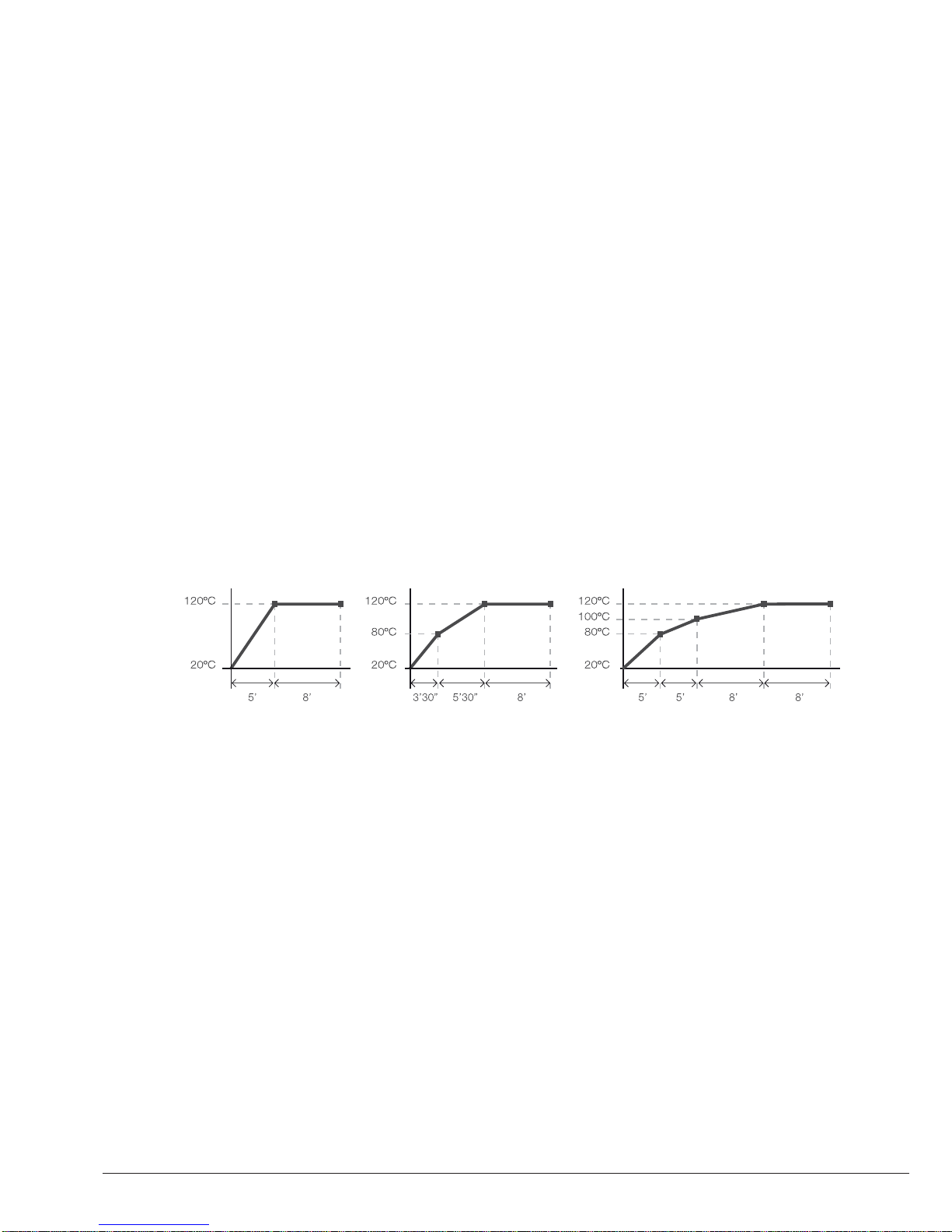
JBCset profiles
There are 3 profiles predefined by JBC: A, B and C. The difference between them is the number
of steps: 2, 3 or 4. The thicker your PCB is and the more layers it contains, the more steps are
needed to obtain a gradual warming.
These profiles are not modifiable but they can be used as a template to create your own profiles.
JBCset A
2 steps
JBCset B
3 steps
JBCset C
4 steps
For repetitive jobs we recommend running profiles without the Thermocouple (TC). Once any
profile has been run to the end, the system has all the process data which you can save.
Once it is saved, you can run this profile without connecting the Thermocouple (TC). The heating
process will the same as long as the same working conditions are respected.
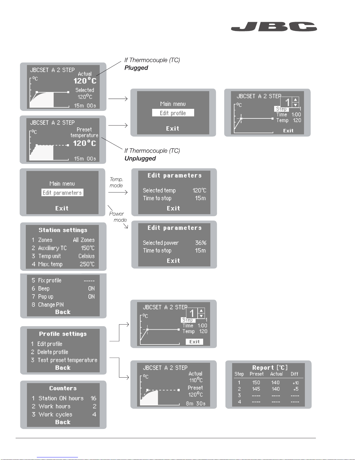
User profiles
You can create your own profiles from the JBCset profiles. On the work screen of the profile,
press the Enter button and choose the option Edit profile.
Power Mode
The unit works at the selected power or temperature during the defined time. These parameters can
be modified from the work screen by pressing the Enter button and the Edit parameters menu.
To see the current temperature you must plug the Thermocouple (TC) into the Control connector.
PCB reference
specifications:
FR4 1,6mm thick
and 2 layers.
FR4 2,2mm thick
and 6 layers.
FR4 1,6mm thick
and 6 layers.
Profiles set using the low position of the PHS-SA Support (28 mm in height between the PCB and the heating area).
4
Page 5
Recommended Guidelines
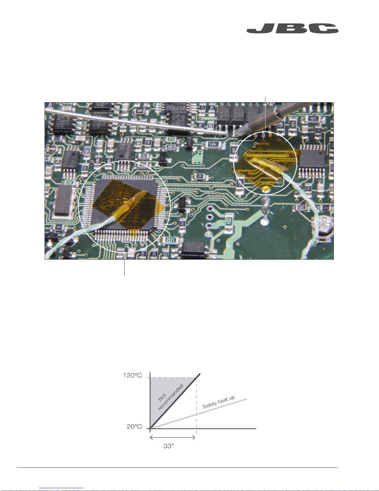
1. Place the Thermocouple (TC) as near as possible to the component being worked on.
2. If there are any sensitive components, use the Auxiliary Thermocouple as protection.
You can select the protection temperature in Station settings. If the selected temperature is
reached, the Heater Unit will stop the process and a warning message will be shown.
3. IPC* does not recommend exceeding ramp-up rates over 3 - 4 °C / sec (5 - 7 °F / sec) so as to
reduce the risk of thermal stress on the PCB.
* IPC was founded in the U.S. in 1957 as the Institute for Printed Circuits and is committed to becoming the
most recognized international industry association for the electronics manufacturing industry.
Fix the TC with Kapton Tape
Auxiliary Thermocouple (TC)
www.jbctools.com
5
Page 6
Display Control
6
Page 7
www.jbctools.com
7
Page 8
Maintenance
Before carrying out maintenance, always allow the equipment to cool.
- Check periodically that the PHS-B is clean.
- Use a damp cloth when cleaning. Alcohol can only be used to clean the metal parts.
Clean
periodically
- Only if it is absolutely necessary and
if cleaning with isopropyl alcohol (IPA) is not
enough, it is recommended to use a scraper
to remove dirt in the glass area.
- Replace any defective or damaged parts.
Use original JBC spare parts only.
- Repairs should only be performed by a JBC
authorized technical service.
8
Page 9

Safety
It is imperative to follow safety guidelines to protect health and prevent electric
shock, injury, fire or explosions.
- Do not use the units for any purpose other than PCB preheating. Incorrect use may cause fire.
- The mains cable must be plugged into approved bases. Make sure that it is properly grounded
before use. When unplugging it, hold the plug, not the wire.
- The temperature of accessible surfaces may remain high after the unit is turned off. Handle with care.
- Do not leave the appliance unattended when it is on.
- Do not cover the ventilation grills. Heat can cause inflamable products to ignite.
- Heat can cause inflamable products to ignite even when out of sight.
- Be careful with the remains of liquid tin. In contact with skin, it can cause burns.
- Avoid flux coming into contact with skin or eyes to prevent irritation.
- Be careful with the smoke produced when soldering.
- Keep your workplace clean and tidy. Wear appropriate protection glasses and gloves when
working to avoid personal harm.
- This appliance can be used by children over the age of eight as well as persons with reduced
physical, sensory or mental capabilities or lacking experience provided that they have been given
adequate supervision or instruction concerning use of the appliance and understand the hazards
involved. Children must not play with the appliance.
- Maintenance must not be carried out by children unless supervised.
www.jbctools.com
9
Page 10

Specifications
IR Preheater
PHS-1B 120V. Input 120V 50/60Hz Fuse 8A
PHS-2B 230V. Input 230V 50/60Hz Fuse 4A
PHS-9B 100V. Input 100V 50/60Hz Fuse 8A
- Weight: 2,9 kg (6.39 lb)
- Dimensions (Heater Unit): 195 x 288 x 41,5 mm (7.68 x 11.34 x 1.63 in)
- Maximum Power: 500W
- Heating Area: 65 x 135 mm (2.56 x 5.31 in - 1 zone)
130 x 135 mm (5.12 x 5.31 in - 2 zones)
- Temperature Range: 50 - 250 °C (120 - 482 ºF)
- Temperature Measurement: Thermocouple type K
- JBCset temperature profiles: 3 profiles (2, 3 or 4 steps)
- User Profiles: 20 (up to 6 steps for each)
- Maximum work time: 600 min or indefinite
Complies with CE standards.
ESD protected housing.
10
Page 11

Precalentador por Infrarrojos
Ref. PHS-B
www.jbctools.com
11
Page 12

Composición
Los siguientes artículos deberían estar incluidos:
Power Cord
Cable de red .......................................... 1 unidad
Ref. 0009417 (100V/120V)
0009401 (230V)
Thermocouple
Termo par (Tipo K) ................................. 1 unidad
Ref. PH218
Kapton Tape
Cinta Kapton ......................................... 1 unidad
Ref. PH217
Manual .................................................. 1 unidad
Ref. 0017241
IR Preheater Precalentador por Infrarrojos .................................................................................. 1 unidad
Ref. PHS-1B (120V)
PHS-2B (230V)
PHS-9B (100V)
Heater Unit
Unidad calefactora
Console
Consola
Ref. PHS-B
IR Preheater
12
www.jbctools.com
Page 13
Características
Conector de Pedal (opcional)
Ref. P-005
Áreas calefactoras
Toma de Red
Interruptor general
Fijadores para el
soporte PHS-SA
Unidad de Control Botón Inicio / paro
Conector para Termopar auxiliar (Tipo K)
Termopar
(Tipo K)
Ref. PH218
Conector USB-B a PC:
Actualice el software
Heater Unit
Unidad calefactora
Console
Consola
Zona A
Zone B
www.jbctools.com
13
Page 14
Perfiles por Temperatura
El modo usual de ejecutar un perfil es utilizando el Termopar (TC) en el conector de Control.
JBC le ofrece 3 perfiles predefinidos (JBCset) y 10 perfiles listos para personalizar (User Profiles).
Funcionamiento
JBCset A
2 pasos
JBCset B
3 pasos
JBCset C
4 pasos
Recomendamos que para trabajos repetitivos, se ejecuten los perfiles sin Termopar: Una vez un
perfil cualquiera se ha ejecutado hasta el final, el sistema dispone de todos los datos del proceso
y pregunta si se desea salvar. En caso afirmativo se podrá ejecutar ese perfil sin tener el termopar
conectado. El proceso de calentamiento será idéntico siempre que se respeten las mismas
condiciones de trabajo.
Perfiles JBCset (JBCset profiles)
Hay 3 perfiles predefinidos por JBC: A, B y C. La diferencia entre ellos es el número de pasos:
2, 3 o 4. Cuanto más grueso sea su PCB y más capas contenga, más pasos serán necesarios
para obtener un calentamiento uniforme y progresivo.
Estos perfiles no son modificables pero pueden ser usados como plantilla para crear sus
propios perfiles (User Profiles).
Perfiles de Usuario
Puede crear sus propios perfiles a partir de los perfiles JBCset. Desde la pantalla de trabajo del
perfil, apriete el botón Enter y elija la opción Edit profile.
PCBs y
condiciones
de referencia:
FR4 de espesor
1,6mm y 2 capas.
FR4 de espesor
2,2mm y 6 capas.
FR4 de espesor
1,6mm y 6 capas.
Por qué Infrarrojos? La tecnología más eficiente para precalentar PCBs
Es el método más avanzado, eficiente y rentable para precalentar PCBs en cualquier trabajo de
soldadura o reparación. La poca masa térmica del elemento infrarrojo proporciona un control
excepcional del calor y de la temperatura del proceso. Esta tecnología ofrece una respuesta rápida,
altas tasas de calor y un calentamiento uniforme que garantiza los mejores resultados.
Modos de potencia
La unidad funciona a la potencia o temperatura seleccionada durante el tiempo establecido.
Estos parámetros pueden ser modificados desde la pantalla de trabajo apretando el botón Enter y
accediendo al menu Edit parameters.
Si desea ver la temperatura actual debe conectar el Termopar en el conector de Control.
Perfiles realizados utilizando la posición baja del soporte PHS-SA (28 mm de altura entre el PCB y el área calefactora).
14
Page 15

Recomendaciones
Cinta Kapton para fijar el Termopar en el PCB
1. Coloque el Termopar tan cerca como sea posible del componente a trabajar.
2. Si hay algún componente sensible, use el Termopar Auxiliar como protección.
Puede seleccionar la temperatura de protección en el menú Station settings. Si la temperatura
llega a la establecida, se interrumpirá el proceso y mostrará un warning.
3. IPC* no recomienda exceder tasas de rampas por encima de los 3 - 4 °C / seg (5 - 7 °F / seg)
con el fin de reducir el riesgo de estrés térmico en los PCBs.
* IPC se fundó en USA en 1957 con el nombre de Institute for Printed Circuits con la intención de convertirse en
la asociación internacional más reconocida de la industria manufacturera electrónica.
Termopar Auxiliar (TC)
www.jbctools.com
15
Page 16

Pantallas de control
16
Page 17

www.jbctools.com
17
Page 18

Mantenimiento
Antes de almacenar o de su mantenimiento, desconecte el equipo y déjelo enfriar.
- Compruebe periódicamente que el precalentador PHS-B esté limpio.
- Utilice un paño húmedo para limpiar. Sólo utilice alcohol para las partes metálicas.
Limpie
periódicamente
- Solo cuando sea absolutamente necesario
y si la limpieza con isopropanol (IPA) no es
suficiente, se recomienda el uso de una
rasqueta para limpiar la suciedad adherida en
la zona del cristal.
- Cambie cualquier pieza defectuosa o dañada.
Utilice solamente recambios originales de JBC.
- Cualquier reparación sólo podría ser realizada
por un servicio técnico oficial JBC.
18
Page 19

Seguridad
- No utilice la unidad para otros fines que no sea el precalentamiento de PCBs. El uso incorrecto
puede causar fuego.
- El cable de red debe enchufarse en bases homologadas. Asegúrese de que está conectado a
tierra antes correctamente antes de su uso. Al desenchufarlo, tire del conector, no del cable.
- La temperatura de las superficies accesibles puede ser alta incluso cuando la unidad está
apagada. Manipule con cuidado.
- No deje el aparato desatendido cuando esté en funcionamiento.
- No cubra las rejillas de ventilación. El calor puede causar que los productos inflamables se enciendan.
- El calor puede causar que los productos inflamables se enciendan aunque no estén a la vista.
- Tenga cuidado con los restos de estaño líquido. En contacto con la piel, puede causar
quemaduras.
- Evite el contacto del Flux con la piel o los ojos para prevenir la irritación.
- Tenga cuidado con el humo producido al trabajar.
- Mantenga su lugar de trabajo limpio y ordenado. Use gafas y guantes de protección adecuados.
Así evitará cualquier daño.
- Este aparato puede ser utilizado por personas a partir de 8 años y también por aquellas
personas con movilidad reducida o capacidades físicas, sensoriales o mentales limitadas o
con falta de experiencia y conocimientos siempre y cuando reciban supervisión o instrucciones
relativas al uso del aparato de una manera segura y entiendan los riesgos que implica. Los niños
no deben jugar con el aparato.
- Los niños no deberán realizar tareas de mantenimiento sin supervisión.
Es necesario seguir estas directrices de seguridad para proteger su salud y
prevenir cualquier choque eléctrico, heridas, fuego o explosiones.
www.jbctools.com
19
Page 20

Especificaciones técnicas
IR Preheater · Precalentador por Infrarrojos
PHS-1B 120V. Entrada 120V 50/60Hz Fusible 8A
PHS-2B 230V. Entrada 230V 50/60Hz Fusible 4A
PHS-9B 100V. Entrada 100V 50/60Hz Fusible 8A
- Peso: 2,9 kg (6.39 lb)
- Dimensiones (Unidad calefactora): 195 x 288 x 41,5 mm (7.68 x 11.34 x 1.63 in)
- Potencia máxima: 500W
- Área calefactora: 65 x 135 mm (2.56 x 5.31 in - 1 zona)
130 x 135 mm (5.12 x 5.31 in - 2 zonas)
- Rango de temperatura: 50 - 250 °C (120 - 482 ºF)
- Medición de temperatura: Termopar Tipo K
- Perfiles predefinidos por JBC (JBCset): 3 perfiles (2, 3, 4 pasos)
- Perfiles de usuario: 20 (hasta 6 pasos para cada uno)
- Tiempo de trabajo máximo: 600 min o indefinido
Cumple con las normativas CE.
Protección ESD.
20
Page 21

IR-Unterheizung
Ref. PHS-B
www.jbctools.com
21
Page 22

Inhalt
Die folgenden Teile sollten in dem Paket enthalten sein:
Power Cord
Netzkabel .................................................. 1 Stück
Ref. 0009417 (100V/120V)
0009401 (230V)
Thermocouple
Thermoelement ....................................... 1 Stück
Ref. PH218
Kapton Tape
Kaptonband ............................................. 1 Stück
Ref. PH217
Handbuch ............................................... 1 Stück
Ref. 0017241
IR Preheater IR-Unterheizung ........................................................................................................... 1 Stück
Ref. PHS-1B (120V)
PHS-2B (230V)
PHS-9B (100V)
Heater Unit
Vorheizgerät
Console
Konsole
Ref. PHS-B
IR Preheater
22
www.jbctools.com
Page 23

Eigenschaften
Steckanschluß für Pedal
Ref. P-005
Heizzonen
Netzanschluss
Netzschalter
Befestigungselemente für PHS-SA
Steuereinheit Start / Stopp
Eingang für Hilfsthermoelement (Typ K)
USB-B Anschluss
zum PC:
Zum aktualisieren der
Steuereinheits-software
Heater Unit
Vorheizgerät
Console
Konsole
Thermoelement
(Typ K)
Ref. PH218
Zone A
Zone B
www.jbctools.com
23
Page 24

Temperature Profiles (Temperaturprofile)
Der übliche Weg, um ein Profil ausführen zu lassen, ist die Verwendung des Thermoelements (TC),
das mit dem Steuereingang der Konsole verbunden wird. JBC bietet drei vordefinierte Profile (JBC
set) und 10 frei zu definierende Profile an.
Warum Infrarot? Die effizienteste Technologie für die PCB Vorheizung
Dies ist die fortschrittlichste, effizienteste und kostengünstigste Methode, um Leiterplatten für jede
beliebige Lötarbeit oder bei Reparaturarbeiten vorzuheizen. Die geringe thermische Masse des
Infrarotelementes bietet eine hervorragende Kontrolle der Heizleistung und der Prozesstemperatur.
Diese Technologie bietet schnelle Reaktionszeiten, hohe Erwärmungsraten und gleichmäßige
Erwärmung, was beste Ergebnisse sicherstellt.
Betrieb
JBCset Profiles (JBC vordefinierte Profile)
Es gibt 3 vordefinierte JBC Profile: A, B und C. Der Unterschied zwischen ihnen ist die Anzahl
der Stufen: 2, 3 oder 4. Je dicker Ihre Leiterplatte ist und je mehr Schichten enthalten sind, desto
mehr Stufen sind notwendig, um eine allmähliche Erwärmung zu erhalten.
Diese Profile können nicht geändert werden, aber sie können als Vorlage verwendet werden, um
eigene Profile zu erstellen.
JBCset A
2 Stufen
JBCset B
3 Stufen
JBCset C
4 Stufen
Für sich wiederholende Arbeiten empfehlen wir Profile ohne Thermoelement (TC) laufen zu
lassen. Sobald ein Profil bis zum Ende ausgeführt wurde, hat das System alle Prozessdaten und
fragt, ob Sie sie speichern möchten. Wenn das der Fall ist, dann können Sie arbeiten ohne dass
das Thermoelement angeschlossen ist. Der Erwärmungsvorgang wird identisch sein, solange die
gleichen Arbeitsbedingungen eingehalten werden.
User profiles (Benutzerprofile)
Basierend auf den JBC Profilen können Sie Ihre eigenen Profile erstellen. Auf dem Bildschirm
drücken Sie die Enter-Taste und wählen die Option Enter Profile.
Power Mode (Energie-Modus)
Das Gerät arbeitet mit der gewählten Leistung während der definierten Zeit. Diese Parameter können
vom Bildschirm aus durch drücken der Enter-Taste und dem Edit Parameters Menu geändert werden.
Um die aktuelle Temperatur zu sehen, müssen Sie das Thermoelement (TC) anschliessen.
PCB
Referenz
Spezifikationen
FR4 1,6 mm dick
und 2 Schichten.
FR4 2,2 mm dick
und 6 Schichten.
FR4 1,6 mm dick
und 6 Schichten.
Profil-Einstellungen (settings) unter Verwendung der niedrigen Position des PHS-SA Halters (28 mm position).
24
Page 25

Empfehlungen
1. Bringen Sie das Thermoelement so nah wie möglich bei der zu bearbeitenden Komponente an.
2. Wenn es ein besonders empfindliches Element auf der Leiteplatte gibt, benutzen Sie ein
zusätzliches Hilfsthermoelement um dieses Bauteil zu schützen. Sie können die Schutztemperatur
in dem Menu Station Settings auswählen. Wenn die gewählte Temperatur erreicht ist, wird das
IR-Vorheiz-System den Prozess stoppen und eine Warnmeldung angezeigen.
Kapton-Band, um das Thermoelement (TC) auf der Leiterplatte zu fixieren
3. IPC* empfiehlt Anstiegsraten von 3 - 4 °C/s nicht zu überschreiten, um die Gefahr von
thermischen Stress auf der Leiterplatte zu reduzieren.
* IPC wurde in den USA im Jahr 1957 mit dem Namen Institute for Printed Circuits (Institut für Leiterplatten) gegründet.
Hilfsthermoelement (TC)
www.jbctools.com
25
Page 26

Menu-Steuerung
26
Page 27

www.jbctools.com
27
Page 28

Wartung
Vor der Durchführung von Wartungsarbeiten oder Einlagerung die Geräte immer erst auskühlen lassen.
- Überprüfen Sie regelmäßig, dass der PHS-B sauber ist.
- Verwenden Sie ein feuchtes Tuch zur Reinigung. Alkohol darf nur zur Reinigung der Metallteile
benutzt werden.
Regelmäßig
reinigen
- Nur wenn es absolut notwendig ist und
wenn die Reinigung mit Isopropanol (IPA)
nicht ausreicht, können Sie zum Beseitigen
von Schmutzresten auf der Scheibe des
Arbeitsbereiches einen Klingenschaber
verwenden.
- Jedes defekte oder schadhafte Teil
austauschen. Nur Original-Ersatzteile von
JBC verwenden.
- Reparaturen dürfen nur von dem Vertragskundendienst von JBC durchgeführt werden.
28
Page 29

Sicherheit
- Setzen Sie das Gerät nicht für einen anderen Zweck als zum Vorwärmen von PCB´s ein. Falsche
Verwendung kann Brand verursachen.
- Das Netzkabel muss in zugelassene Steckdosen eingesteckt werden. Vergewissern Sie sich vor
der Benutzung, dass sie korrekt geerdet ist. Beim Herausziehen, am Stecker ziehen, nicht am
Kabel.
- Die Temperatur von zugänglichen Oberflächen kann hoch sein, auch wenn das Gerät ausges
chaltet ist. Vorsicht beim Umgang.
- Lassen Sie das Gerät nicht unbeaufsichtigt, wenn es in Betrieb ist.
- Die Kühlungsgitter nicht abdecken. Hitze kann entzündliche Stoffe entzünden, sogar wenn sie
sich außerhalb der Sichtweite befinden.
- Hitze kann dazu führen, brennbare Produkte zu entzünden, auch wenn diese nicht sichtbar sind.
- Seien Sie vorsichtig mit den Überresten von flüssigem Zinn. Bei Kontakt mit der Haut, kann es zu
Verbrennungen führen.
- Ein als “ohne Rückstände” eingestuftes Flussmittel verwenden und die Berührung mit Haut oder
Augen vermeiden, um Reizung zu vermeiden.
- Sich vor dem beim Löten entstehenden Rauch in Acht nehmen.
- Ihren Arbeitsplatz sauber und aufgeräumt halten. Bei der Arbeit geeignete Schutzbrille und
Handschuhe tragen, um gesundheitliche Schäden zu vermeiden.
- Dieses Gerät kann von Kindern ab 8 Jahren und älter und von Personen mit eingeschränkten
physischen, sensorischen oder geistigen Fähigkeiten oder mit mangelnder Erfahrung und Wissen
benutzt werden, wenn eine angemessene Aufsicht oder ausführliche Anleitung zur sicheren
Benutzung des Gerätes erfolgte und die damit verbundenen Gefahren verstanden wurden Kinder
dürfen nicht mit dem Gerät spielen.
- Wartung darf nicht von Kindern durchgeführt werden, wenn sie hierbei nicht beaufsichtigt werden.
Es ist zwingend notwendig den Sicherheitsrichtlinien zu folgen, um die
Gesundheit zu schützen und Stromschlägen, Verletzungen, Brand oder
Explosionen vorzubeugen.
www.jbctools.com
29
Page 30

Technische Daten
IR Preheater · IR-Unterheizung
PHS-1B 120V. Eingang 120V 50/60Hz Sicherung 8A
PHS-2B 230V. Eingang 230V 50/60Hz Sicherung 4A
PHS-9B 100V. Eingang 100V 50/60Hz Sicherung 8A
- Gesamtgewicht: 2,9 kg (6.39 lb)
- Abmessungen (Vorheizgerät): 195 x 288 x 41,5 mm (7.68 x 11.34 x 1.63 in)
- Maximale Leistung: 500W
- Heizfläche: 65 x 135 mm (2.56 x 5.31 in - 1 zone)
130 x 135 mm (5.12 x 5.31 in - 2 zonen)
- Temperaturbereich: 50 - 250 °C (120 - 482 ºF)
- Temperaturmessung: Thermoelement Typ K
- JBCset Temperaturprofile: 3 profile (2, 3, 4 Schritte)
- Benutzerprofile: 20 (bis zu 6 Schritte für jedes Profil)
- Maximale Arbeitszeit: 600 min oder unbegrenzt
Erfüllt EG-Normen.
ESD-gerechtes Gehäuse.
30
Page 31

红外线预热器
Ref. PHS-B
www.jbctools.com
31
Page 32

清单
应包含以下项目:
Heater Unit
加热器平台
Console
控制器
Power Cord
电源线 ............................................................. 1 件
Ref. 0009417 (100V/120V)
0009401 (230V)
Thermocouple
热电偶 ............................................................. 1 件
Ref. PH218
Kapton Tape
卡普顿胶带 ..................................................... 1 件
Ref. PH217
说明书 ............................................................ 1 件
Ref. 0017241
IR Preheater 红外线预热器 ..................................................................................................................... 1 件
Ref. PHS-1B (120V)
PHS-2B (230V)
PHS-9B (100V)
Ref. PHS-B
IR Preheater
32
www.jbctools.com
Page 33

特性
踏 板 接口连 接(可 选)
Ref. P-005
加热区域
固定支架
PHS-SA 支架
Heater Unit
加热器平台
Console
控制器
控制屏 启动/停止
备用热电偶 ( K型)
热电偶 (K型)
Ref. PH218
USB-B 电脑连接头:
更新控制单元软件
A区
B区
电源输入
电源开关
www.jbctools.com
33
Page 34

Temperature profiles (温度曲线)
通常运行曲线时使用连接到控制台的控制输入的热电偶(TC)。
JBC提供3个预定义的曲线(JBC配置)和10个为你准备好的可个性化的曲线。
操作
JBC配置 A
2 步
JBC配置 B
3 步
JBC配置 C
4 步
对于重复性工作,我们建议使用没有热电偶(TC)的曲线。
一旦曲线已经运行完毕,系统会储存所有过程中的数据。
储存后,你就可以在没有热电偶(TC)的情况下直接运行曲线。
只要工作条件一致加热过程始终都是一样的。
JBCset profiles (JBC配置 曲线)
有 3个 预 定 义 的 曲 线:A,B 和 C 。它 们 之 间 的区 别 是 步 数:2,3 或 4 。
印 刷 电 路 板 越 厚,层 数 越高,就 需 要更 多 的 步 骤,以得 到 逐 渐 升 温 。
这些曲线不可修改,但它们可以被用来作为模板创建自己的曲线。
User Profiles (用户定义曲线)
你可以利用JBC配置曲线创建自己的曲线。
在曲线工作屏上按下回车键并选择编辑曲线。
线路板: FR4 1,6mm 厚度
和 2 层。参数
FR4 2,2mm厚 和 6 层
FR4 1,6mm 厚 和 6 层
为什么红外线?这是线路板加热最有效的技术。
这是焊接或返工中线路板预热的最先进,有效而经济的方法。
红外线元件的低热容为热度输出和过程温度提供了出色的控制。
该技术响应快速,具有高加热功率和均匀加热,确保了最好的结果。
Power Mode (功率 )
本机在预定时间内按照选择的功率工作。
这些参数的修改可以自工作屏上的回车键后在参数菜单里编辑。
要看到现有工作参数,你必须将热电偶(TC)插入控制连接器内。
曲线设置使用PHS-SA线路板支架低档(28mm在线路板和加热区域之间)。
34
Page 35

推荐指南
固定TC的卡普顿胶带
1. 将热电偶(TC)尽可能接近到正在工作的组件。
2. 如果有敏感组件,请使用辅助热电偶保护。
你可在工作台设置中选择保护温度。如果达到保护 温度,IR预热器会停止运行,警告信息会出现。
3. IPC*建议加速率不超过3 - 4°C/秒(5 - 12°F/秒),以减少线路板上热应力的风险。
* IPC 于1957年在美国成立,全名为线路板学院。
辅助热电偶 (TC)
www.jbctools.com
35
Page 36

屏幕控制
36
Page 37

www.jbctools.com
37
Page 38

维护
在维护或储存之前需确保设备已经冷却。
- 定期检查PHS-B是否清洁。
- 清洁时使用湿布。
酒精只可用来清 洁金属部件。
- 只有在非常有必要,并且无法通过异丙醇
(IPA)清洁干净的时候,建议使用刮刀清洁玻
璃区域吸附的污垢。
- 更换任何受损的元件。仅使用JBC原装配件。
- 修理必须由JBC专业技术服务人员进行。
定期清洁
38
Page 39

安全注意事项
- 不要使用本产品用于焊接或返修以外的任何目的。不正确使用可能造成火灾。
- 电源线必须插入核准的电源。确保使用前妥善接地。拔掉电源时握住插头,而不是电线。
- 请勿在带电部件上操作。
- 该工具在不使用时应放置在支架上,以激活休眠模式。烙铁头,金 属 部 分 和 支 架 即 使 在 焊台被切
断电源时仍旧是热的。小心轻放,包括调整支架位置时。
- 设备开着时,切勿无人看管。
- 请勿覆盖通风口。热量可引起易燃物品引燃。
- 使用“无残渣”类锡丝,避免与皮肤或眼睛接触,以防刺激。
- 小心焊接时产生的烟雾。
- 保持工作场所干净整洁。操作时,为避免造成人身伤害,请穿戴适当的防护眼镜和手套。
- 残锡液易引起灼伤,请小心处理。
- 本产品允许八岁以上儿童,肢体,感官或心智有残缺的人士,以及缺乏经验的人士使用,
但必须提供必要的监护及指导,并且了解本产品可能涉及的危险。切勿让儿童把玩。
- 没有监管,儿童不得对本产品进行维护。
必须遵循安全规范,以保护健康,预防触电,人身伤害,火灾或爆炸。
www.jbctools.com
39
Page 40

技术参数
IR Preheater · 红外线预热器
PH S-1B 120V. 输入120V 50/60Hz 保险丝 8A
PHS-2B 230V. 输入230V 50/60Hz 保险丝 4A
PHS-9B 100V. 输入100V 50/60Hz 保险丝 8A
- 总重: 2,9 kg (6.39 lb)
- 尺寸 (加热器平台): 195 x 288 x 41,5 mm (7.68 x 11.34 x 1.63 in)
- 最大功率: 500W
- 加热区域: 65 x 135 mm (2.56 x 5.31 in - 1 个区)
130 x 135 mm (5.12 x 5.31 in - 2 个区)
- 温度范围: 50 - 250 °C (120 - 482 ºF)
- 温度计测: K型热电偶
- 3 JBC配置 温度曲线
- 用户配置曲线: 最多 20个 (每个配置最多6个)
- 最大工作时间: 600 分钟 / 无限的
符合CE标准。
ESD保护壳。
40
Page 41

Notes
www.jbctools.com
41
Page 42

Exploded View · Despiece · Explosionszeichnung · 分解图
42
Page 43

www.jbctools.com
43
Page 44

保修
JBC的2年保修涵盖了该设备所有的制造缺陷,包括更换有缺陷的零件和人工耗时。保修不包括因过度使用或误用
而产生的产品损坏。为了使保修有效,设备须返还至购买时的经销商处返修,邮资自理。
请在购买后30天内在www.jbctools.com/productregistration注册您的产品保修信息。
本产品不应被扔在垃圾筒内。
根据欧盟条款2012/19/EU,电子设备在其寿命结束后必须被回收并转运至授权回收工厂。
Garantie
Die 2-Jahres-Garantie von JBC ersteckt sich auf das Gerät bei Herstellungsfehlern, einschließlich Fehlern der
Verarbeitung und dem Ersatz defekter Teile und deren Austausch. Die Garantie gilt nicht für Produktverschleiß
durch normale Nutzung oder durch falsche Anwendung. Damit die Garantie Gültigkeit erlangt, muß das Gerät an
den Händler, bei dem es gekauft wurde, zurückgesand weden (Porto bezahlt). Bitte registrieren Sie Ihr Equipment
nach dem Kauf innerhalb von 30 Tagen unter folgendem Link www.jbctools.com/productregistration.
Dieses Produkt sollte nicht mit dem Hausmüll entsorgt werden.
In Übereinstimmung mit der europäischen Richtlinie 2012/19/EU müssen elektronische Geräte am
Ende ihrer Lebensdauer eingesammelt und einem autorisierten Recyclingbetrieb zugeführt werden.
Garantía
Esta garantía de 2 años cubre este equipo contra cualquier defecto de fabricación, incluyendo la sustitución
de partes defectuosas y mano de obra. La garantía no cubre el desgaste del producto por uso o mal uso. Para
que esta garantía sea válida, el equipo debe ser devuelto, a portes pagados, al distribuidor donde se compró.
Registre la garantía de su producto dentro de los 30 días de la compra en www.jbctools.com/productregistration.
Este producto no debe desecharse en la basura.
De acuerdo a la directiva europea 2012/19/UE, los equipos electrónicos al final de su vida se deberán
recoger y trasladar a una planta de reciclaje autorizada.
0017241-0817
Warranty
JBC’s 2 year warranty covers this equipment against all manufacturing defects, including the replacement of
defective parts and labour. Warranty does not cover product wear or misuse. In order for the warranty to be valid,
equipment must be returned, postage paid, to the dealer where it was purchased. Please register your warranty
within 30 days of purchase in www.jbctools.com/productregistration.
This product should not be thrown in the garbage.
In accordance with the European directive 2012/19/EU, electronic equipment at the end of their life
must be collected and returned to an authorized recycling facility.
www.jbctools.com
 Loading...