

Page 1
Nano Rework Station
Ref. NASE-C
INSTRUCTION MANUAL
www.jbctools.com
Page 2
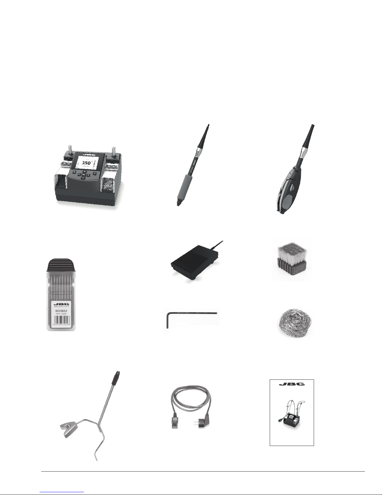
Adjustable Nano
Twee zers ........................ 1 unit
Re f. AN115 - A
Manual ............................ 1 unit
Ref. 0021447
Metal Brush ................... 1 unit
Ref. CL2466
Brass Wool .................... 1 unit
Ref. CL6210
Power Cable .................. 1 unit
Ref. 0009417 (
100/120V )
0009401 (230V)
Nano Rework station
Ref. NASE-C
Packing List
The following items are included:
Control Unit ................... 1 unit
Ref. NAE-1C (120V)
NAE-2C (230V)
NAE-9C (100V)
Nano Handle ................. 1 unit
Re f. NT115 - A
Cartridge
dispenser Case .......... 2
units
Ref. 0020952
0020953
Ref. 0020952:
Ref. C115-101 x1
C115-103 x1
C115 -107 x1
C115 -112 x1
Ref. 0020953:
Ref. C115-105 x2
C115 -113 x 2
Allen key ........................ 1 unit
Ref. 009848
Pedal................................ 1 unit
Ref. P-405
Tool Holder .................. 2 units
Ref. 00166 06
INSTRUCTION MANUAL
2
www.jbctools.com
Page 3
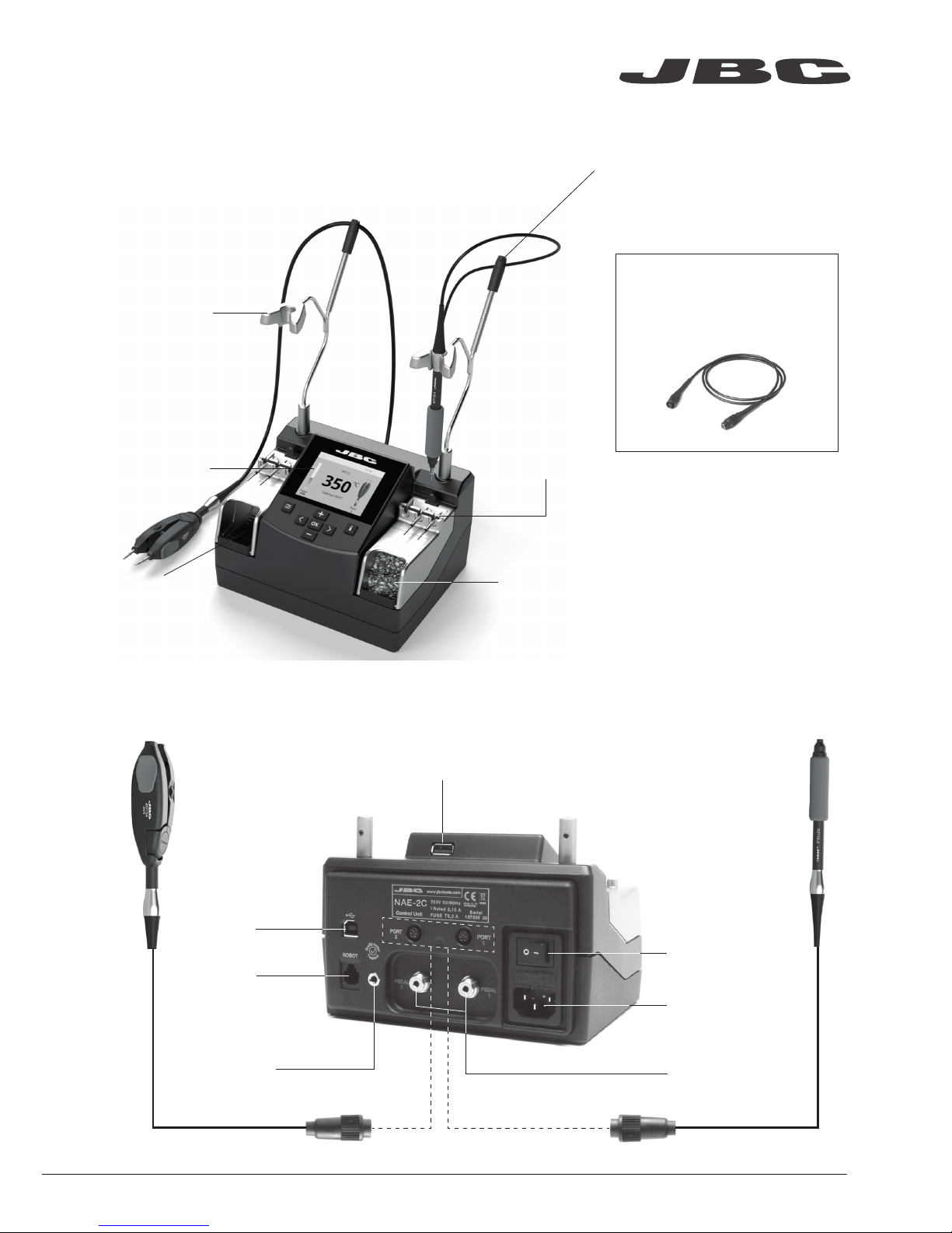
Nano Handle
Re f. NT115 - A
Adjustable Nano
Twee zers
Re f. AN115 - A
Features
Tool extension cord (1m)
Ref. A1205
Accessories not included:
Process
Screen:
2.8 Color TFT
Cartridge
extractor
and tip aligner
Brass wool
Metal brush
Stand:
Intelligent Heat
Management
Cable collector
Power socket
Main switch
Equipotential
connector
Pedal connectors
USB-B
connector
RJ12
connector
for Robot
USB-A connector
www.jbctools.com
3
Page 4
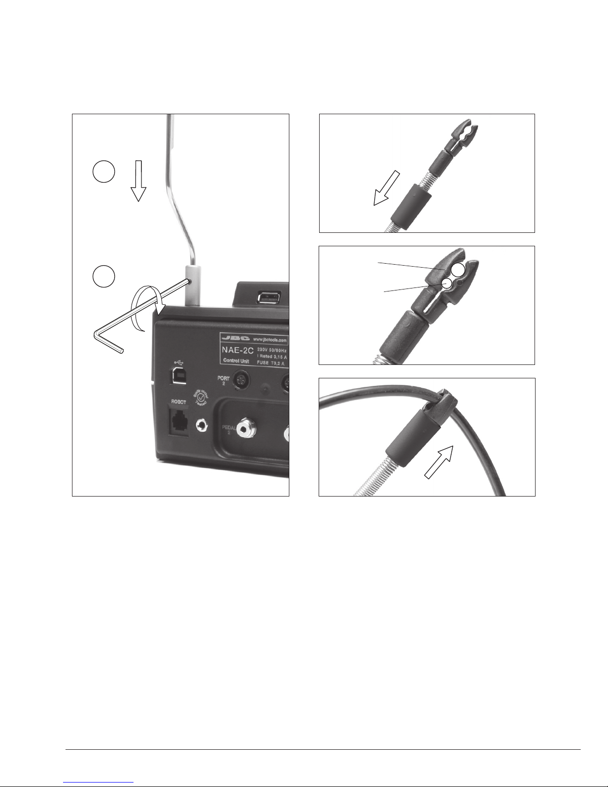
For tool
NT115-A
For tool
AN115-A
Tool Holder assembly Cable assembly
1
2
4
Page 5
380
ºC
Port
1
Power
45%
Temp. Levels
T470
250 380 400
17:14
350
ºC
Port
2
Power
45%
Temp. Levels
250 350 380
17:14
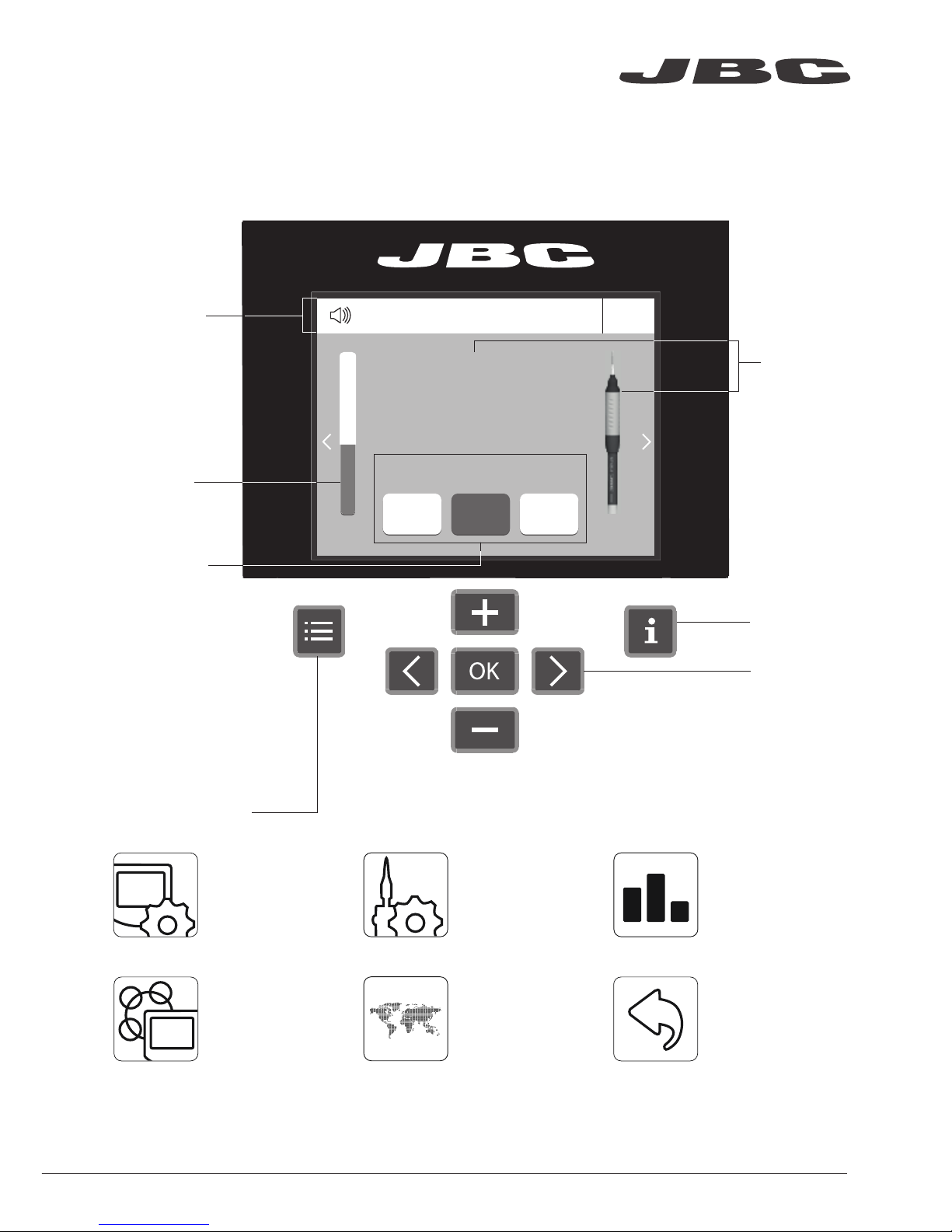
NT115
Menu Options
Station
Information
Power
indicator
Tool
in use
Work Screen
Status bar
The NASE-C offers an intuitive user interface which provides quick access to station parameters.
Default PIN: 0105
Change
port
Displayed if
temperature
levels are
activated
Station Tools Counters
ResetLanguagePeripherals
Set the station
parameters
Set the tool
parameters
Consult / modif y the
links of the peripherals
connected to the
station with the port
they are connected to.
Display the hours
worked in each cycle
It is possible to
choose the language
from a list.
Allows you to carry
out an overall station
reset restoring all the
parameters to their
default values.
www.jbctools.com
5
Page 6

JBC Net
Export graphics
Insert a USB flash drive into the
USB-A connector to save your
soldering process in csv format.
Advanced functionalities
It provides detailed graphics of tip temperature and power delivery in real time during
solder joint formation for analysis purposes. This helps you decide how to adjust your
process or which tip to use to obtain the best quality soldering.
Graphics
The first system to optimize traceability in soldering
- Get greater quality and control in your production
- Manage your whole soldering process remotely in real time
USB flash drive is connected.
Station is controlled by a PC.
Station is controlled by a robot.
System notifications
Station software update.
Press INFO to start the process.
Warning.
Press INFO for failure description.
Error.
Press INFO for failure description,
the type of error and how to proceed.
The following icons will be displayed on the screen’s status bar.
Station update
Download the JBC Update File from
www.jbctools.com/software.html
Insert the USB flash drive with the
file downloaded to the station.
Files
Update
6
Page 7

2
17:14
Hibernatio
n
Actual Temp. 25ºC
Port
2
350
ºC
Port
2
Power
45%
17:14
Selected 350ºC
NT115
NT115
Operation
The JBC Exclusive Heating System
Our revolutionary technology is able to recover tip temperature extremely quickly. It means the user
can work at a lower temperature and improve the quality of soldering. The tip temperature is further
reduced thanks to the Sleep and Hibernation modes which increase the tip life by 5.
2. Hibernation
1. Wor k
When the tool is lifted from the holder the tip
will heat up to the selected temperature.
When the tool is in the holder, the power
is cut off and the tool cools down to room
temperature.
Tools Menu:
· Set temperature limits
· Set temperature levels
Tools Menu:
· Set Hibernation delay (from 0
to 60 min or no Hibernation)
www.jbctools.com
7
Page 8
1
ROBOT
2
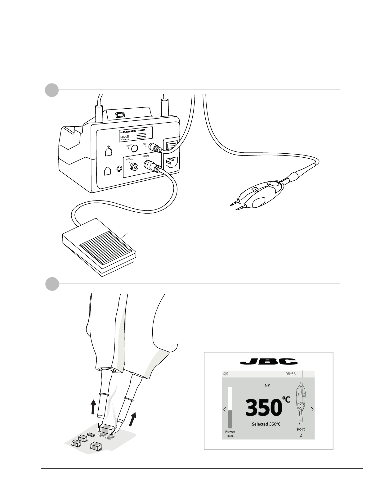
Chip Compoments Rework proces using Tweezers and pedal
Pedal
Ref. P-405
Press and hold the pedal to heat the tool
and desolder the component.
The Adjustable Nano Tweezers is the most effective tool for desoldering chip components
but also it facilitates its rapid placement and soldering by using the P-405 pedal connected
to the station.
Connections
Connect pedal P-405 to the same port
where de Nano Tweezers are connected.
Desoldering
8
Page 9

4
3
Clean the pads with the desoldering tool
DS360-A*.
* Secondary station is needed.
Apply the solder paste amount needed to
solder the new chip component.
Pad cleaning
Solder paste dispensing
www.jbctools.com
9
Page 10

6
5
Use the tool to position the component on
the previously tinned pads.
Placing
Soldering
Once in position, press and hold the pedal
to perform the soldering.
10
Page 11

1
2,5
Compatible cartridges
The NT115-A and AN115-A work with C115 cartridges. Find the model that best suits your soldering
needs on www.jbctools.com
Conical
Chisel
Bevel
Knife
Conical
bent
High thermal
performance
Stainless
steel chisel
Changing cartridges
Save time and change cartridges safely without having to switch the station off.
Removing
Inserting
Aligning
Place the cartridge in the slot
as shown and pull the handle
to remove it.
Push the cartridge into the
handle to the mark*.
Use the holes to rotate
the cartridges for a proper
alignment.
*Important
It is essential to insert the cartridges as far as the reference for a proper connection.
Reference
1
2
www.jbctools.com
11
Page 12
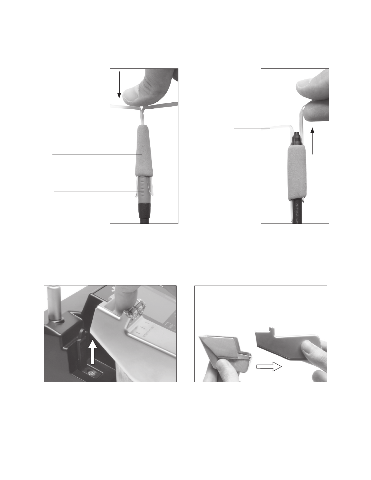
Changing grips
1. Push the grip with
the tabs onto the
handle.
2. To remove the
tabs, hold the grip
and pull them out.
Use a pliers if
necessary.
Nano handle
Grip for NT115-A
Tabs
Replace the tip cleaning system:
- Brass wool
- Metal brush
Changing the tip cleaning system
12
Page 13

Maintenance
Before carrying out maintenance or storage, always allow the equipment to cool.
- Clean the station screen with a glass cleaner
or a damp cloth.
- Use a damp cloth to clean the casing and the
tool. Alcohol can only be used to clean the
metal parts.
- Periodically check that the metal parts of the
tool and stand are clean so that the station
can detect the tool status.
- Maintain tip surface clean and tinned prior to
storage in order to avoid tip oxidation. Rusty
and dirty surfaces reduce heat transfer to the
solder joint.
- Periodically check all cables and tubes.
- Replace a blown fuse as follows:
- Replace any defective or damaged pieces. Use original JBC spare parts only.
- Repairs should only be performed by a JBC authorized technical service.
1. Pull off the fuse holder and remove the
fuse. If necessary use a tool to lever it off.
2. Press the new fuse into the fuse holder
and replace it in the station.
Fuse holder
Fuse holder
Fuse
www.jbctools.com
13
Page 14

It is imperative to follow safety guidelines to prevent electric
shock, injury, fire or explosion.
Safety
- Do not use the units for any purpose other than soldering or rework. Incorrect use may cause fire.
- The power cord must be plugged into approved bases. Be sure that it is properly grounded
before use. When unplugging it, hold the plug, not the wire.
- Do not work on electrically live parts.
- The tool should be placed in the stand when not in use in order to activate the sleep mode.
The soldering tip, the metal part of the tool and the stand may still be hot even when the station is
turned off. Handle with care.
- Do not leave the appliance unattended when it is on.
- Do not cover the ventilation grills. Heat can cause inflamable products to ignite.
- Avoid the contact of flux with skin or eyes to prevent irritation.
- Be careful with the fumes produced when soldering.
- Keep your workplace clean and tidy. Wear appropriate protective glasses and gloves when
working to avoid personal harm.
- Utmost care must be taken with liquid tin waste which can cause burns.
- This appliance can be used by children over the age of eight and also persons with reduced
physical, sensory or mental capabilities or lack of experience provided that they have been given
adequate supervision or instruction concerning use of the appliance and understand the hazards
involved. Children must not play with the appliance.
- Maintenance must not be carried out by children unless supervised.
14
Page 15

产品中有害物质的名称及含量
有害物质含量表
部件名称
有害物质
铅(Pb) 汞(Hg) 镉(Cd)
六价铬
(Cr(VI))
多溴联苯
(PBB)
多溴二苯醚
(PBDE)
烙铁头 O O O O O O
手柄 O O O O O O
电源线 O O O O O O
主机 O O O O O O
电源插座 O O O O O O
保险丝 O O O O O O
主开关 O O O O O O
电位连接 X O O O O O
变压器 O O O O O O
线路板 X O O O O O
O 表示该有害物质在该部件所有均质材料中的含量均在GB/T 26572 规定的限量要求以下。
X 表示该有害物质至少在该部件的某一均质材料中的含量超出GB/T 26572 规定的限量要求。
www.jbctools.com
15
Page 16

This product should not be thrown in the garbage.
In accordance with the European directive 2012/19/EU, electronic equipment at the end of its life
must be collected and returned to an authorized recycling facility.
Warranty
JBC’s 2 year warranty covers this equipment
against all manufacturing defects, including the
replacement of defective parts and labour.
Warranty does not cover product wear or misuse.
In order for the warranty to be valid, equipment
must be returned, postage paid, to the dealer
where it was purchased. Please register your
product warranty within 30 days of purchase
in www.jbctools.com/productregistration.
Specifications
NASE-1C 120V 50/60Hz. Input fuse: 0.5A. Output: 8.5V
NASE-2C 230V 50/60Hz. Input fuse: 0.2A. Output: 8.5V
NASE-9C 100V 50/60Hz. Input fuse: 0.5A. Output: 8.5V
- Temperature Range: 90 - 450 °C (190 - 840 ºF) ±5%
- Idle Temp. Stability (still air): ±3 ºC (±5.5 ºF)
- Output Peak Power: 14W per tool
- Idle Temp. Stability (still air): ±3 ºC (±5.5 ºF)
- Tip to ground voltage: <2 mV
- Tip to ground resistance: <2 ohms
- Ambient operating temp: 10 - 50 ºC (50 - 122 ºF)
- Connections: USB-A / USB-B / Pedal connectors
RJ12 connector for Robot
- Net Weight: 2,5 kg (5.40 lb)
- Dimensions: 170 x 90 x 135 mm (6.70 x 3.54 x 5.31 in)
Complies with CE standards
ESD Safe
0021447-0319
www.jbctools.com
 Loading...