

Jaypro Sports FBGP-920AX User Manual
Installing the Jaypro Max-1 With
Adustable Crossbar
Football Goal Posts
Model:
FBGP-420AX/FBGP-920AX (Expandable18’6’’-23’4’ with 20FT Uprights)
© 2011 Jaypro Sports
WWW.JAYPRO.COM Page 1 11/1/13

1 Introduction
This user guide describes how to install the Jaypro Max-1 football goal post models
FBGP-920AX and FBGP-420AX. The telescoping feature of the crossbar allows the
Max-1 foot ball goal post to be set at either 23’-4’’ between uprights for the official High
School use or 18’ 6’’ for official College width.
This user guide is written for experienced mechanical contractors. If you need
additional information or support to install your Jaypro goal post, you can reach the
Jaypro Sports customer support team, Monday through Friday, 8:00 A.M. to 5:00 P.M.
Eastern Time at 1–800–243–0533.
IMPORTANT NOTICE
It is the installer’s responsibility to ensure that the goalpost, gooseneck, and
crossbar are properly located and lined up with respect to the field. Proper location
and alignment should be confirmed with each step.
It is the installer’s responsibility to ensur e that the crossbar is level and th e uprig hts
are plumb.
o All critical holes are to be drilled by the installer in an effort to help
ensure that all components are square, plumb, and level.
o Verify after every drilling operation that affected components are still
square, plumb, and/or level. Correct as necessary.
o It is recommended that drilled holes be piloted with a 3/16” drill bit, and
opened up incrementally to the final size.
2 Safety
Some of the goal post components are heavy and require at least three people to
maneuver into place. To maintain control and prevent injury when moving heavy
components, ensure you have a sufficient number of technicians to support the
components without dropping them.
3 Equipment and M at er ials
Gather the following user-supplied equipment and materials:
Equipment to excavate a 72- by 36-inch hole
20-foot high scaffold (or scissor lift or boom)
10-foot (minimum) high step ladder
WWW.JAYPRO.COM Page 2 11/1/13

Mechanic’s tool set
Wrench Set
Level, 3’ minimum
100-foot tape measure
Electric Drill
Drill Bits:
o 5/16“, 1/2", and 5/8” bits
Rubber mallet
The following equipment is optional, but strongly recommended:
17/32”, 21/32”, and 11/16” transfer punches (highly recommended)
3/16”, 3/8” drill bits to pilot holes (highly recommended)
Heavy grease or white lithium grease
Antiseize Lubricant
Baling wire (if using rebar)
(6), 54-inch lengths of 5/8-inch rebar
4 Check Components
Goal posts are sold in pairs. Inspect your goal post shipment and ensure you received
these parts:
Parts List
2 Goosenecks
2 Anchor Kits
2 Crossbars
4 Twenty foot uprights
4 Upright end fittings
4 Wind socks
Yellow spray paint
Check to confirm that your Goal Post has shipped with all hardware. If any hardware
or components are missing, contact the Jaypro Sports customer support team, Monday
through Friday, 8:00 A.M. to 5:00 P.M. Eastern Time at 1–800–243–0533 for
replacements.
WWW.JAYPRO.COM Page 3 11/1/13
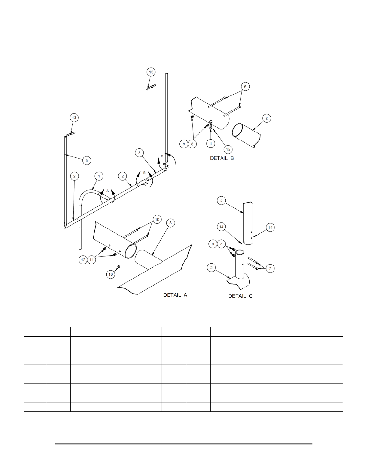
Figure 1: FBGP-900AX & FBGP-400AX Included Components and Hardware
ITEM
QTY
DESCRIPTION
ITEM
QTY
DESCRIPTION
1 1 6 5/8 in GOOSENECK
9
8
1/2 in SAE FLAT WASHER
2 1 ADJUSTABLE CROSSBAR
10
2
5/8-11 x 7 1/ 2 HX HD BOLT
3 2 ADJ END FITTING
11
2
5/8 in FLAT WASHER
4 2 ANTI-ROTATION BOLT
12
2
5/8-11 NYLOCK NUT
5 2 20 FT UPRIGHT
13
1
STREAMER
6 6 1/2-13 x 8 in HX HD BOLT
14
6
1/4-20 1/4 in SET SCREW-CONE POINT
7 4 1/2-13 x 5 HX HD BOLT
15
2
1/4-20 -1/4 in SET SCREW NYLON TIP
8 8 1/2-13 THIN NYLOCK NUT
16
2
3/8-16 x 3/4 in HX HD SELF TAP BOLT
FIGURE 1
WWW.JAYPRO.COM Page 4 11/1/13

5. Where to Install the Foundation and Goosenecks
Installing the foundation and anchors in the proper location at each end of the field
ensures that the gooseneck, cross bar, and uprights will be positioned according to
high school and college football regulations. By rule, the front edge of the crossbar
should be even with the inside edge (field side) of the end line, such that the crossbars
measure 360 ft apart, inside to inside
1. From the field layout plan, determine and mark the location of the inside
corners of the playing field including the end zone.
2. From the field layout plan or through consultation with the field contractor
determine the final field elevation.
3. Using the corners as reference points, mark the points exactly 80 feet in
from the inside edge of the sideline and 100-3/8 inches for FBGP 900 Series
Goal Posts (82-3/8 inches for FBGP 400 Series) in from the inside edge
of the end zone at each end of the field (Figure 2)
NOTE: The dimensions provided account for the deflection of the g ooseneck under t he
weight of the crossbar and uprights.
1
NFHS Football Rules Book, 2009
2
NCAA Football Rules and Interpretations, 2002
1,2
. Follow these steps to locate foundation.
WWW.JAYPRO.COM Page 5 11/1/13
 Loading...