


Jaypro Sports FBGP-720 User Manual

4
3
2
1
FBGP-720
FOOTBALL GOAL
SPECIFICATIONS
23'-4''
Ø2 3/8'' x 3/8'' wall
B B
ALUMINUM UPRIGHTS
INSIDE
HIGH SCHOOL REF
18'-6''
INSIDE
COLLEGE REF
20'
UPRIGHTS
REV
DC
A
30'
OVERALL
HEIGHT
FAX:
800.444.1779 (SALES)
860.440.0628 (ENG.)
CHKD BY
SHEET
1 1
OF
BTS
Ø4 1/2'' x 23' 4'' High School
GOOSENECK Ø5 9/16 x .258 WALL
GALVANIZED STEEL
78 in OFFSET
A A
54 in
36 in
SIDE VIEW
T:\Aftermarket\Football\Drawings\FGBP-720\SPECIFICATIONS\PAGE ONE.idw
REV: A 7/14/2010
4
Ø4 1/2'' X 18' 6'' College
GALVANIZED STEEL CROSSBAR
PLAYING
SURFACE
FBGP-720 HIGH SCHOOL WHITE
FBGP-720YW HIGH SCHOOL YELLOW
FBGP-720C COLLEGE WHITE
FBGP-720XCYW COLLEGE YELLOW
3
FRONT VIEW
2
10 '
TO CROSSBAR
PHONE:
800.243.0533 (TOLL FREE)
860.447.3001 (LO CAL)
JAYPRO SPORTS, LLC, 976 HARTFORD TURNPIKE, WATERFORD, CT 06385 USA
DESCRIPTION
FBGP-720 SPECIFICATIONS
PART NUMBER
FBGP-720
SIZE
SCALE
B
N/A
THIS DRAWING IS THE SOLE PROPERTY O F JAYPRO SPORTS INC. AND MAY
NOT BE REPRODUCED WITHOUT WRITTEN PERMISSION OR CONSENT
DATE
www.jaypro.com
DWN BY
7/10/2006
1

FBGP-720 SERIES
OFFICIAL 6’ OFFSET FOOTBALL GOAL POST
- PERMANENT AND SEMI-PERMANENT INSTALLATIONS -
LIST OF MATERIALS
ITEM NO. PART NO. DESCRIPTION QTY.
1 HS5119 Bolt-HX HD ½”-13x5” 8
2 HS5066 Bolt-HX HD ½”-13x7 ¾” 4
3 HN268 ½”-13 LOCK NUT 12
4 HW2044 ½” FLAT WASHER 12
5 HS1616 Bolt-3/8”-16x2 ¾” 8
6 HN1230 3/8”-16 LOCK NUT 8
7 HW2047 3/8” FLAT WASHER 8
8 SR167 ½-13 x 8 in THREADED ROD 1
9 HN5038 ½-13 FLANGE NUT 2
IMPORTANT
1) The location of the gooseneck with respect to the field is critical. By rule, the
front of the crossbar should be even with the field side (inside) edge of the end
line such that the crossbars measure 360 ft apart, inside to inside. The distance
from the end line to centerline of the bottom upright (gooseneck) is approximately
78” for the FBGP-720 series. See Figure 1
2) The footing depth is dependant on the type of installation, permanent or semipermanent. For permanent installations see Figure 3. For a semi-permanent using
a standard ground sleeve (Part No. FBSLV6) see Figure 4, and for a semipermanent with height adjuster see Figure 5. Materials for the semi-permanent
with height adjuster installation (Part No. FBGPGS-6) include the ground sleeve,
height adjuster and hardware.
3) Concrete should be a minimum 4000-psi mix.
4) The crossbar should be level and at a height of 10 ft above ground level. The
uprights should be plumb in both directions, front to back and side to side.
Adjust goal components as necessary. Note that a certain amount of deflection in
the crossbar is to be expected due to the weight of the end fittings and uprights on
each end.
T:\Aftermarket\Football\Drawings\FGBP-720\DOCUMENTATION\FBGP-720 Installs.doc
REV D 4/10
1
SLEEVE AND GOOSENECK INSTALLATION
1) Excavate the footing hole to the appropriate dimensions shown. See Figure 1 and
2 for locating the footing and height of the gooseneck. Use Figure 3 for
dimensions required for permanent installations. Use Figure 4 for semipermanent installations with a standard ground sleeve (FBSLV6) and Figure 5 for
semi-permanent installations with sleeve and height adjuster option (FBGPGS-6).
2) Once hole is excavated re-check depths to assure the correct crossbar height (10’
0”) will be achieved. Note: Due to the weight of the crossbar and uprights the
gooseneck will deflect downward approximately 1” to 1-1/2”.
3) Create a 6” base by using a concrete block or pouring a level pad 6” in the bottom
of the hole. Allow 48 hours to cure. Once the 6” pad has cured, center your
lower upright (gooseneck) in the hole; making sure the upright is perpendicular
and square to the playing field. Adequately support the gooseneck to prevent any
movement and allow to cure for a full 48 hrs.
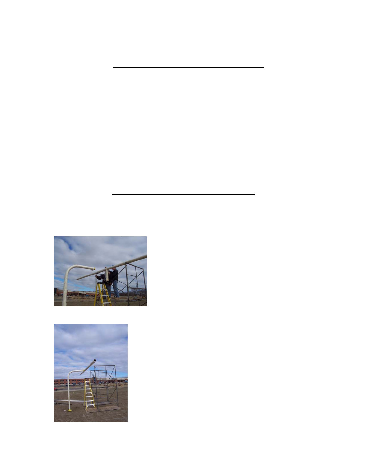
Cross-bar and Upright Installation
Once the footing is complete and the concrete has set for 48 hours, next install the
crossbar.
Crossbar Installation:
Use 10’ scaffolding and a ladder, have two people on
the scaffolding to lift and move the crossbar. Now with a third person on the ladder
guide the insert into the gooseneck.
Insert crossbar into gooseneck. Set crossbar depth so the front
edge of the crossbar is inline with the inside edge (field side) of the end line. Once the
T:\Aftermarket\Football\Drawings\FGBP-720\DOCUMENTATION\FBGP-720 Installs.doc
REV D 4/10
2

crossbar is level, mark (by using a center punch) and drill the holes through the
gooseneck. Start with a 3/16” bit, then a 3/8” bit and finally a ½” bit.
Mark and Drill Crossbar:
Once the holes are drilled, use the ½” bolts with two flat washers and thin lock nut. Use
a Silicon sealant used on each side of the bolt to prevent corrosion.
Tightening ½” bolts between crossbar and gooseneck:
T:\Aftermarket\Football\Drawings\FGBP-720\DOCUMENTATION\FBGP-720 Installs.doc
REV D 4/10
3