


11/06/2007
JARLTECH
ISO 9001 Certified
Lead with technology
Win customers with service
Touch POS System
SERIES 8805
OPERATION
Verson:1.0
MANUAL

1
8805 Touch POS User’s Manual
Table of Contents:
Chapter 1 Introduction ..................................................................................................2
Chapter 2 Appearance ...................................................................................................4
Chapter 3 Installation ....................................................................................................6
Chapter 4 Commands for Peripheral Controlling .....................................................88
Chapter 5 Hardware Configuration .......................................................................... .91
Chapter 6 Hardware Specification ............................................................................. 105
Appendix – LAN Controller........................................................................................ 117

2
8805 Touch POS User’s Manual
CHAPTER 1
Introduction
Preview
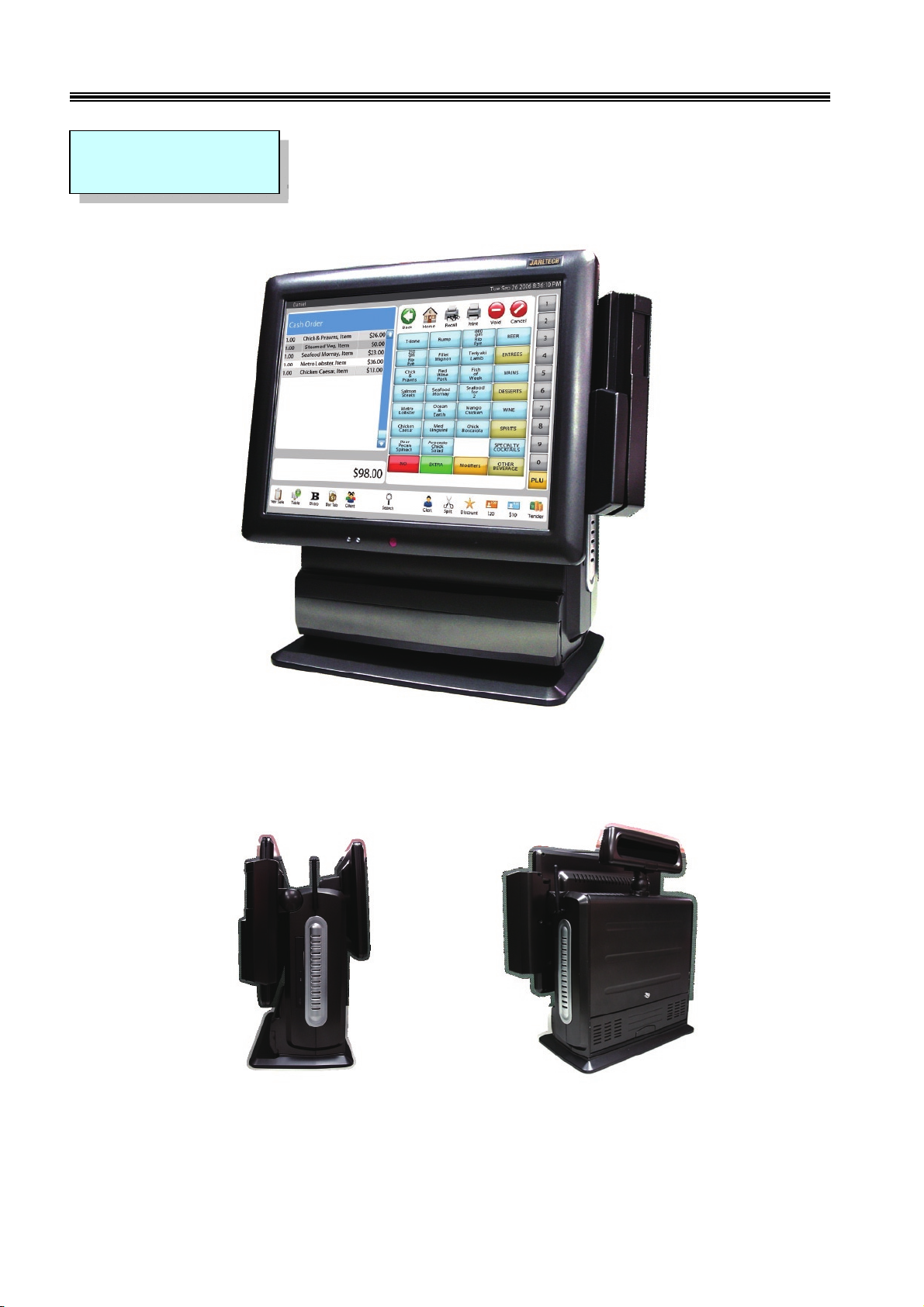
Jarltech is defining the New Age of POS with its integrated TouchPOS. The 8805 is designed on NB base
with Intel Celeron M processor 1 GHz or above, Two slot of DDR SODIMM memory max up to 2GB; 15”
TFT-LCD with resistive touch screen; built-in VGA, LAN chip, Internal IDE Hard disk (20GB or above).
Thus designation helps user easy and comfortable to handle. Its multi-functional capability makes it
suitable for software developments under Windows XP, XP Embedded, XP professional for Embedded,
WIN 2000 professional Embedded, WIN NT 4.0, Linux, Redhat 7.2, WIN98, ME.
The 8805’s functionality extends far beyond the standard setup. 8805 can be adapted for a variety of uses
with the addition of any of the following options: Magnetic Card Reader,Smart Card Reader, 20 x 2 VFD
customer display, the second 10.4" TFT LCD display, cashdrawer, i-Button , Fingerprint ,Wi-Fi ,RFID ,
USB Key-locker or USB devices (all available upon request).
The brand new Touch POS 8805 has been designed with all advantages from JARLTECH POS series, but
less cost to customer with its interactive transaction, RFID and smart card reader design provides multiple
clerk access and customer database management, suitable and superior for super-market, hotel, convenience
store, restaurants and any organization or store that needs point of service.
Notes: Must to adjust display setting in BIOS first.
Advanced Chipset Features
On-Chip VGA Setting Boot Display [CRT+LCD]
Panel Type [1024x768 24Bit 1CH]

3
8805 Touch POS User’s Manual
FCC
This device complies with part 15 of the FCC rules. Operation is subject to the
following two conditions:
(1) This device may not cause harmful interference
(2) This device must accept any interference received, including interference that may
cause undesired operation.
CE MARK
This device complies with the requirements of the EEC directive
89/336/EEC with regard to “Electromagnetic compatibility” and
73/23/EEC “Low Voltage Directive”.
CAUTION ON LITHIUM BATTERIES
There is a danger of explosion if the battery is replaced incorrectly. Replace only with
the same or equivalent type recommended by the manufacturer. Discard used
batteries according to the manufacturer’s instructions.
LEGISLA TION AND WEEE SYMBOL
2002/96/EC Waste Electrical and Electronic Equipment Directive on the
treatment, collection, recycling and disposal of electric and electronic devices
and their components.
4
15" TFT color
display with touch
screen
Smart Card Reader
Magnetic Stripe Reader
Power Led
HDD Led
RFID
Wi-Fi IEEE 802.11
b/g
The second 10.4"
TFT LCD Display
Slim Type CD-ROM
Speaker
20X2 VFD
Customer Display
I/O Port
i-Button
Fingerprint identification
USB Locker
8805 Touch POS User’s Manual
CHAPTER 2
Appearance
5
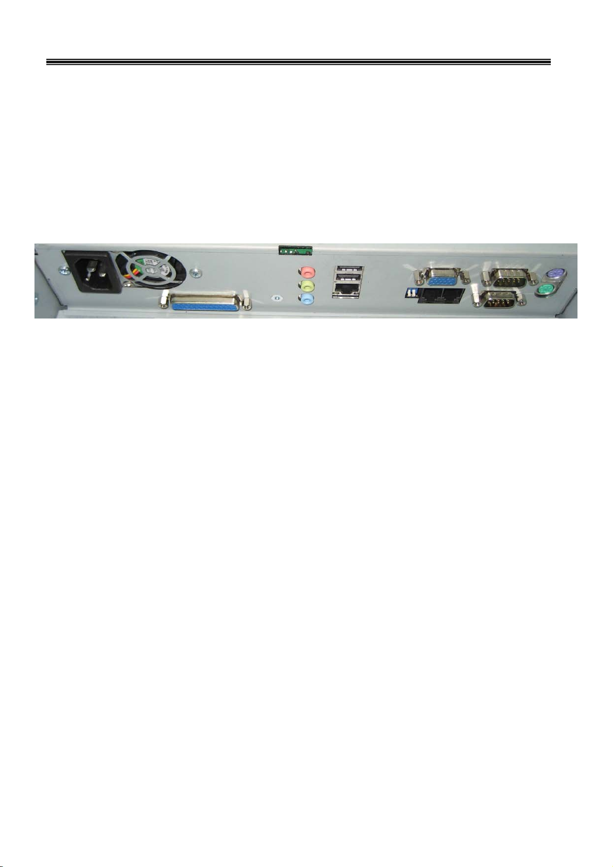
Mouse Port
VGA Port
COM1 COM2
USB Port *2
LAN Port
Audio In/Out
Printer Port
AC Power
Power Fan
K/B Port
CD1/CD2
S/W 1&2
8805 Touch POS User’s Manual
COM1/COM2: Standard DB9 PIN Serial port
Mouse: PS2 mouse socket
K/B: PS2 Keyboard socket
USB: USB port X 2
VGA: 15 Pins VGA Connector
LAN: Ethernet connector
Multi-Media: Line Out / MIC / Line-In
CD1/CD2: Cash Draw 1(beside S/W) and Cash Draw 2
S/W: Switch button – S/W1 S/W2; ↓ = ON, ↑= OFF (Default S/W1=OFF , S/W2=OFF)
Power: Connect to ATX power supply
CAUTION:While installing any additional hardware device, please make sure to
shut down the computer power.
(USB device is not subject to the limits.
)

6
8805 Touch POS User’s Manual
CHAPTER 3
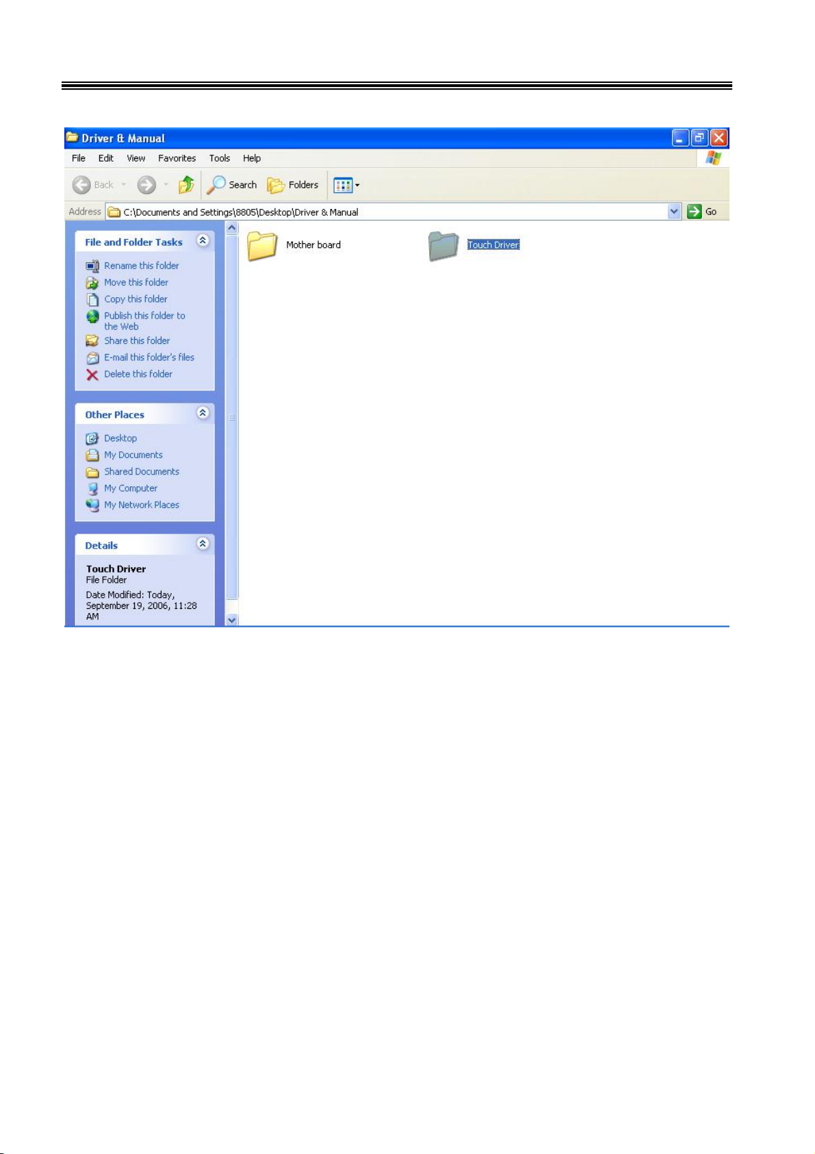
Driver Installation
Touch Drivers
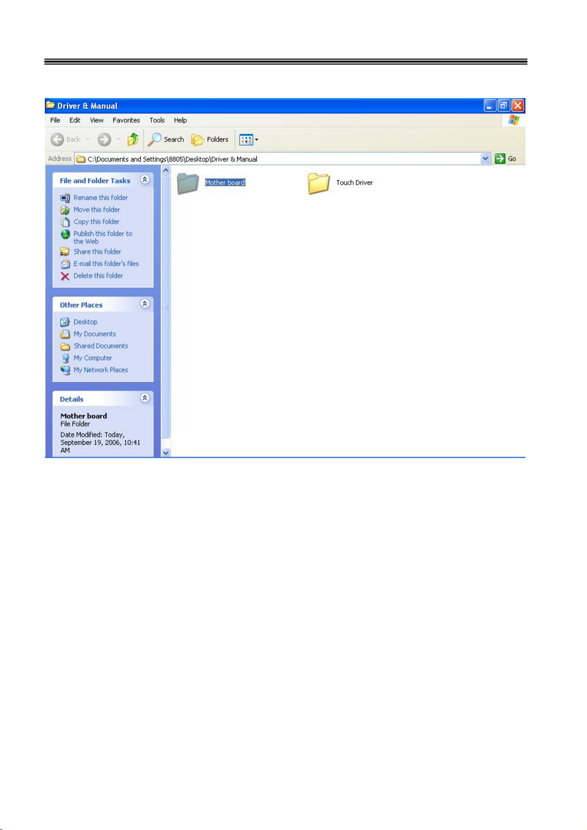
Insert CD Rom and select "Driver & Manual" folder.
7
8805 Touch POS User’s Manual
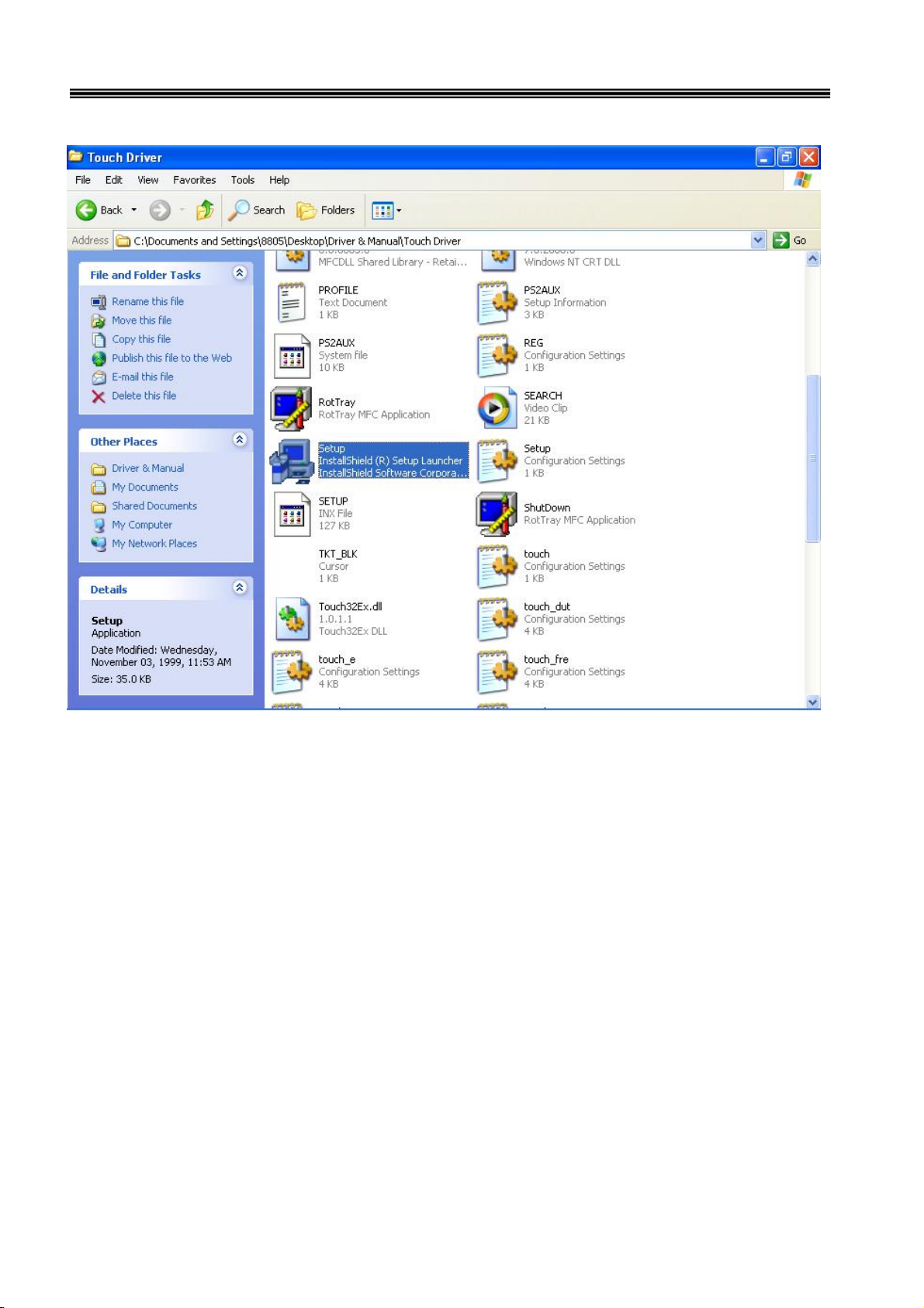
Select "Touch Driver" folder.
8
8805 Touch POS User’s Manual
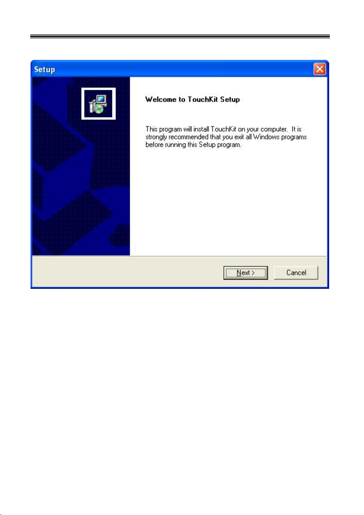
Access the "Setup".
9
8805 Touch POS User’s Manual
When the setup screen appears then to select "Next" step.
10
8805 Touch POS User’s Manual
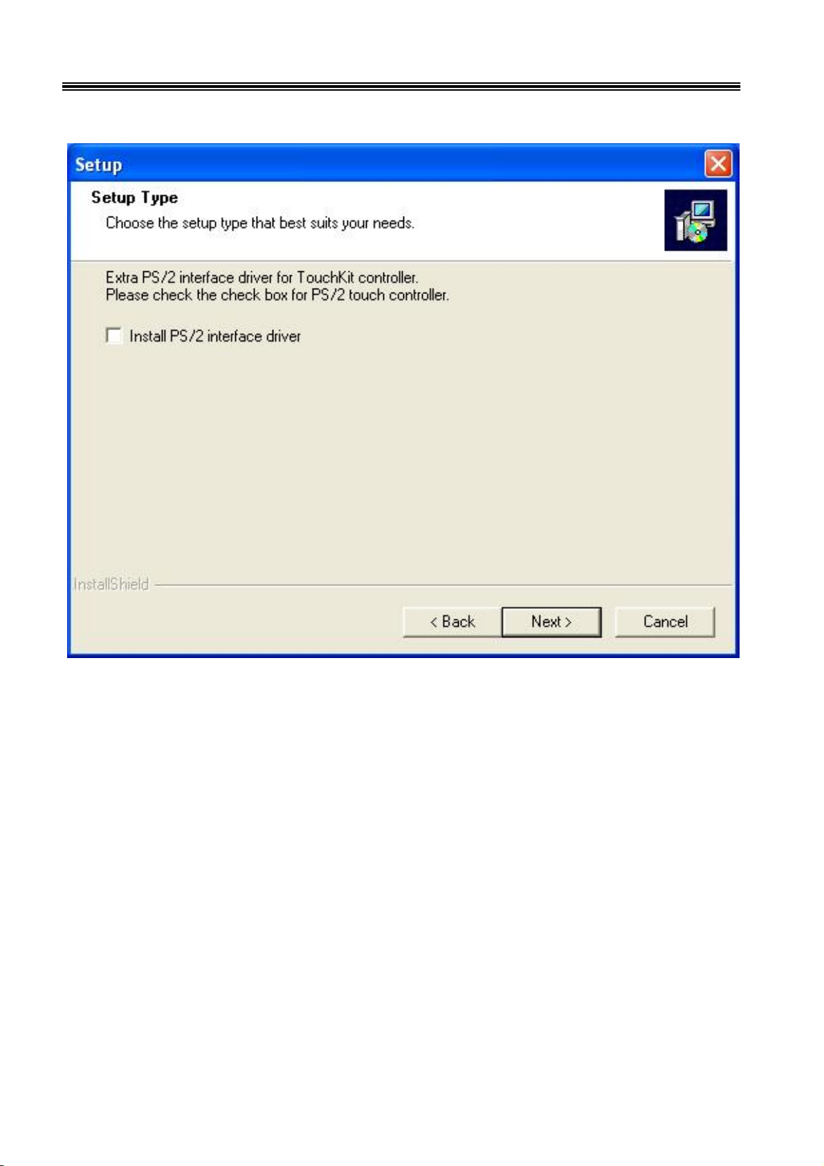
When the setup screen appears then to select "Next" step.
11
8805 Touch POS User’s Manual
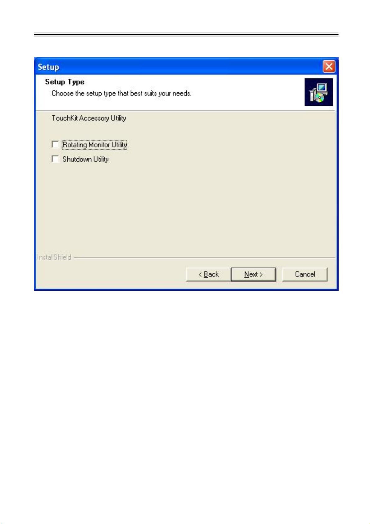
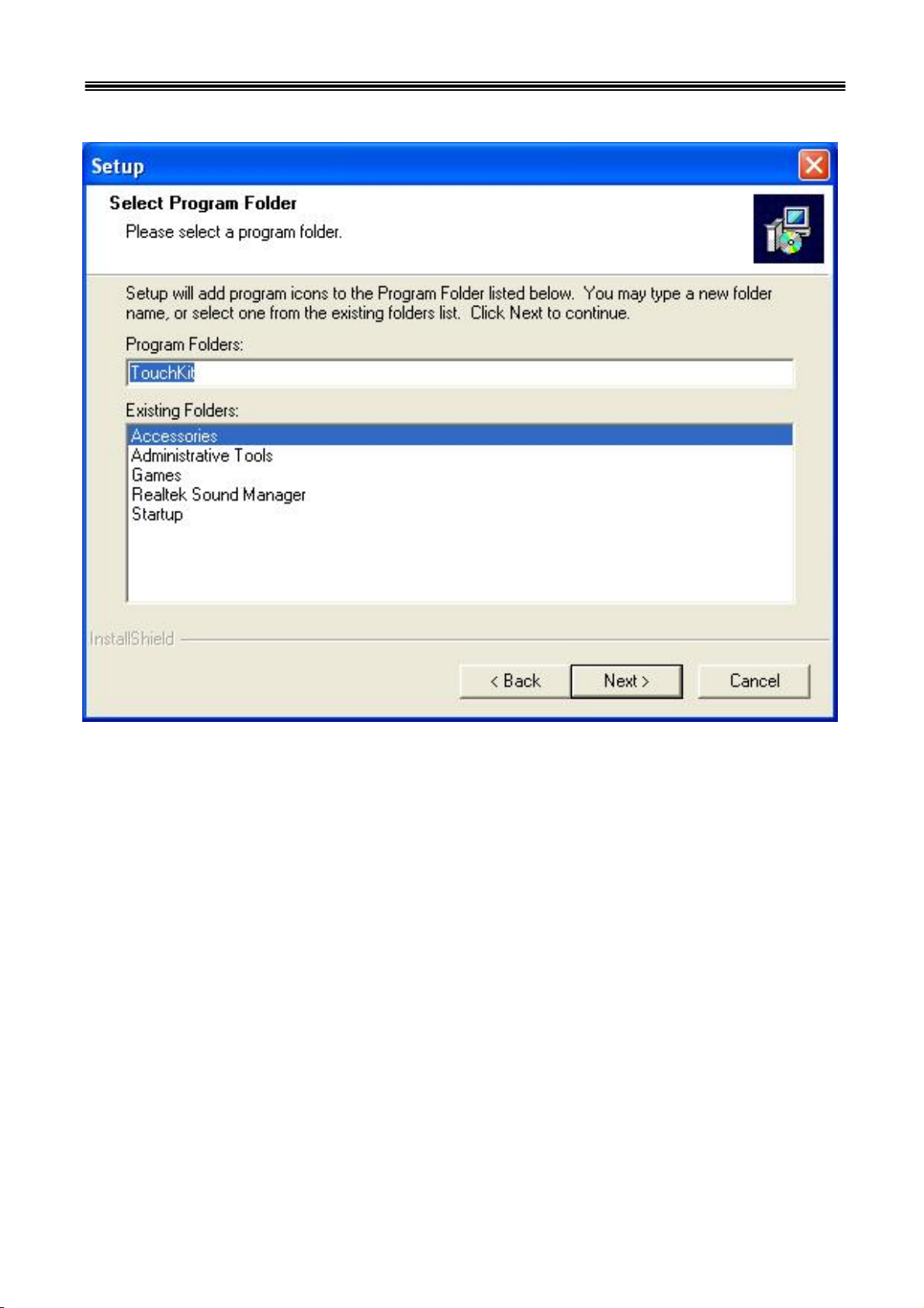
When the setup screen appears then to select "Next" step.
12
8805 Touch POS User’s Manual
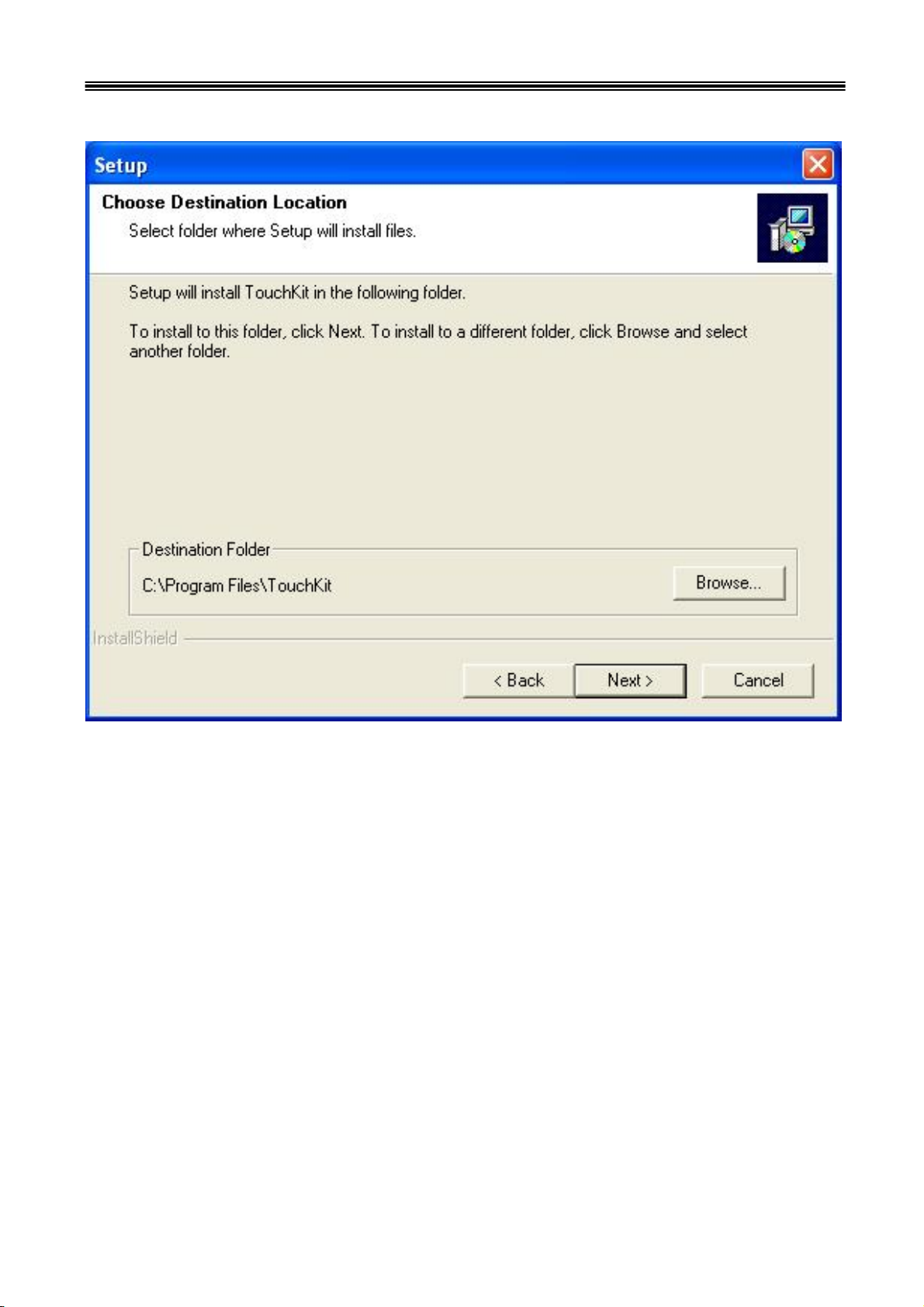
When the setup screen appears then to select "Next" step.
13
8805 Touch POS User’s Manual
When the setup screen appears then to select "Next" step.
14
8805 Touch POS User’s Manual
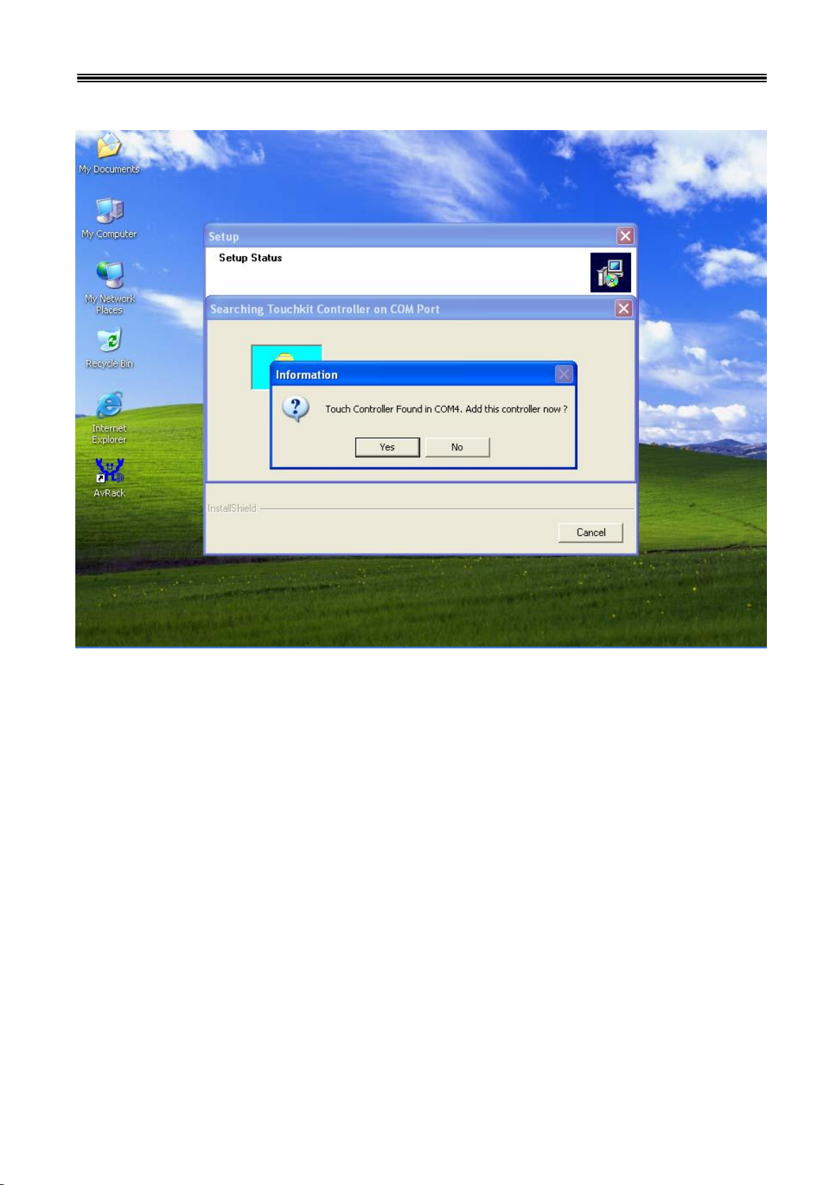
When the setup screen appears then to select “ YES”.
15
8805 Touch POS User’s Manual
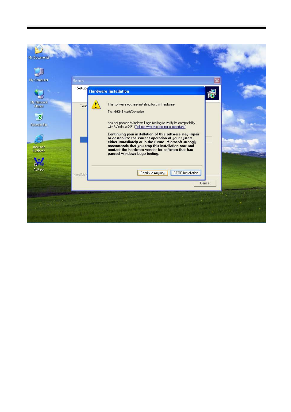
When the setup window appear then to select the “Continue Anyway”.
16
8805 Touch POS User’s Manual
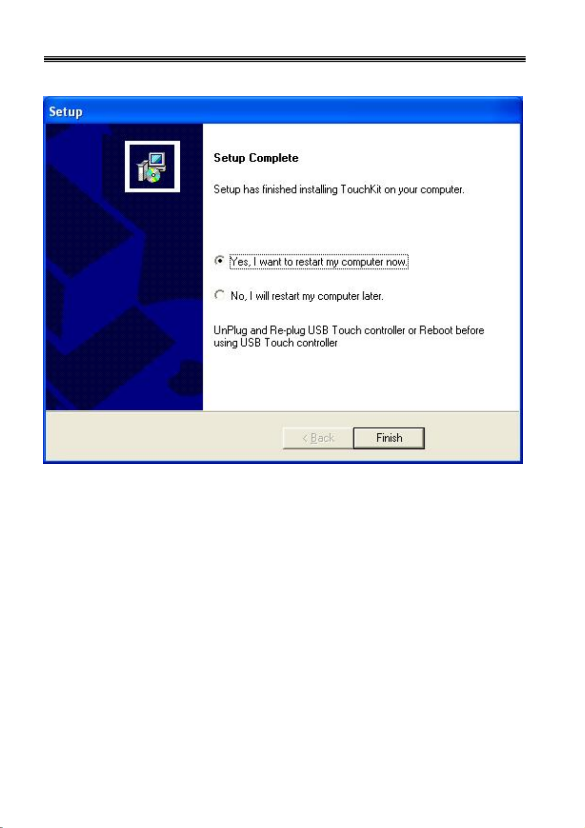
After installation
System will require reboot
select “ YES”

17
8805 Touch POS User’s Manual
When first time complete Touch installation, require processing the cursor accuracy
calibration, Search for the Touchset utility shortcut on the desktop and select
Touchset utility to set up.
18
8805 Touch POS User’s Manual
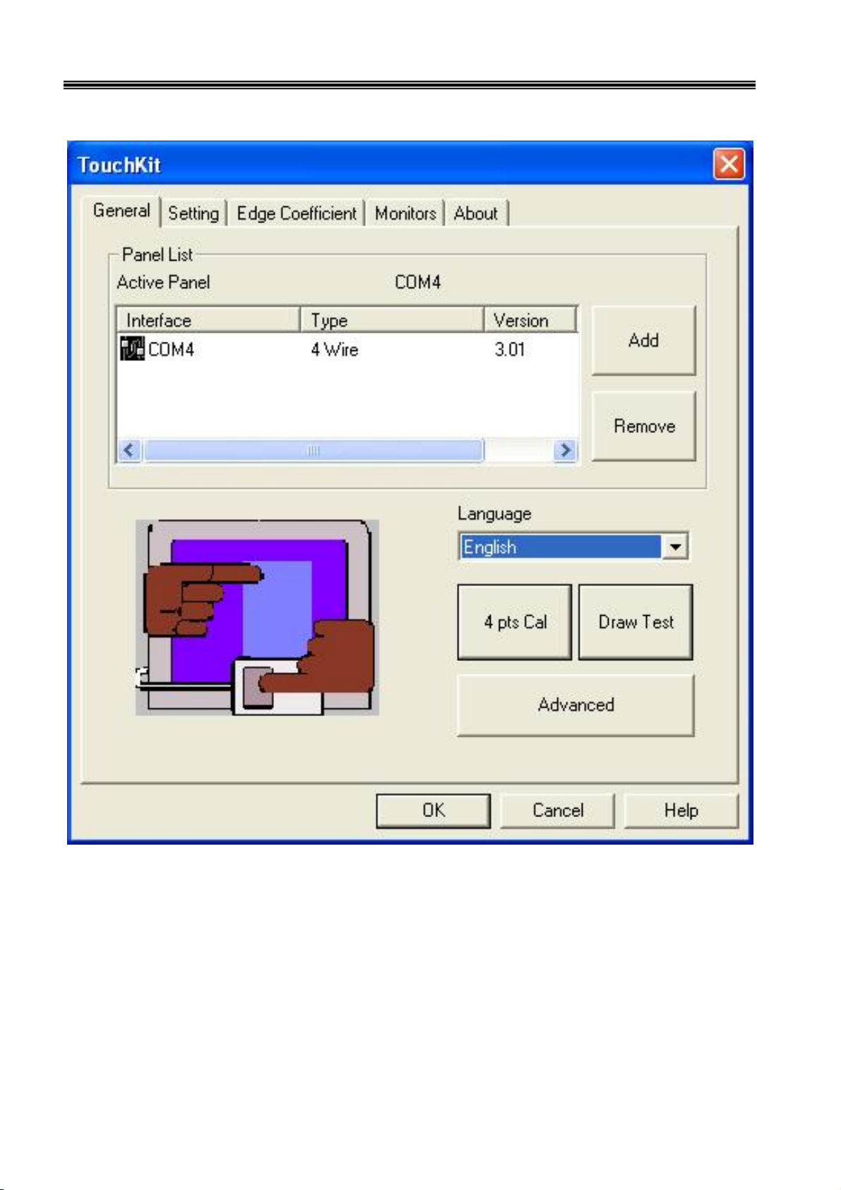
When configuration window appear, select the language which you desire.
(As above selected picture explanation)
19
8805 Touch POS User’s Manual
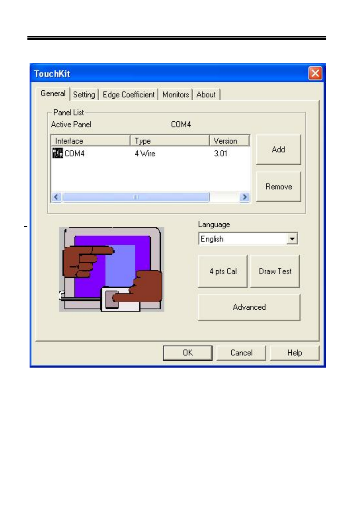
Then to select calibration function and select numbers of calibration point first
(above picture shows select by 4 numbers) next to click on calibrate button.
20
8805 Touch POS User’s Manual
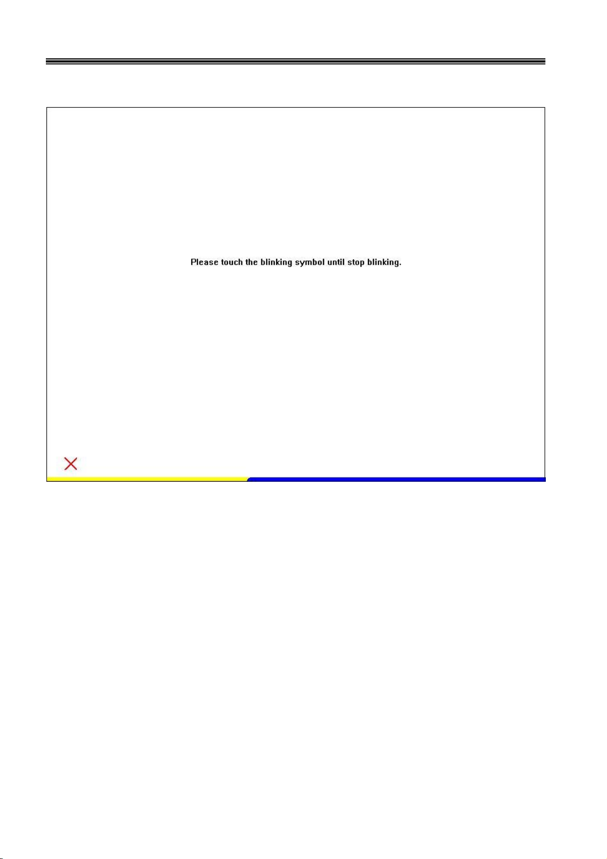
The screen will shows as above picture, use the Touch pen to point on dot to align the
cursor, if the actual alignment has too much difference then the system will skip back
to previous screen and require calibration once again.

21
8805 Touch POS User’s Manual
The numbers of the calibration point shows on the screen will depend on the number
you have set previously, after complete system will skip back to desktop (if the cursor
still not accurate please repeat the calibration again).

22
8805 Touch POS User’s Manual
IDE Drivers
Insert CD Rom and select "Driver & Manual" file folder.
23
8805 Touch POS User’s Manual
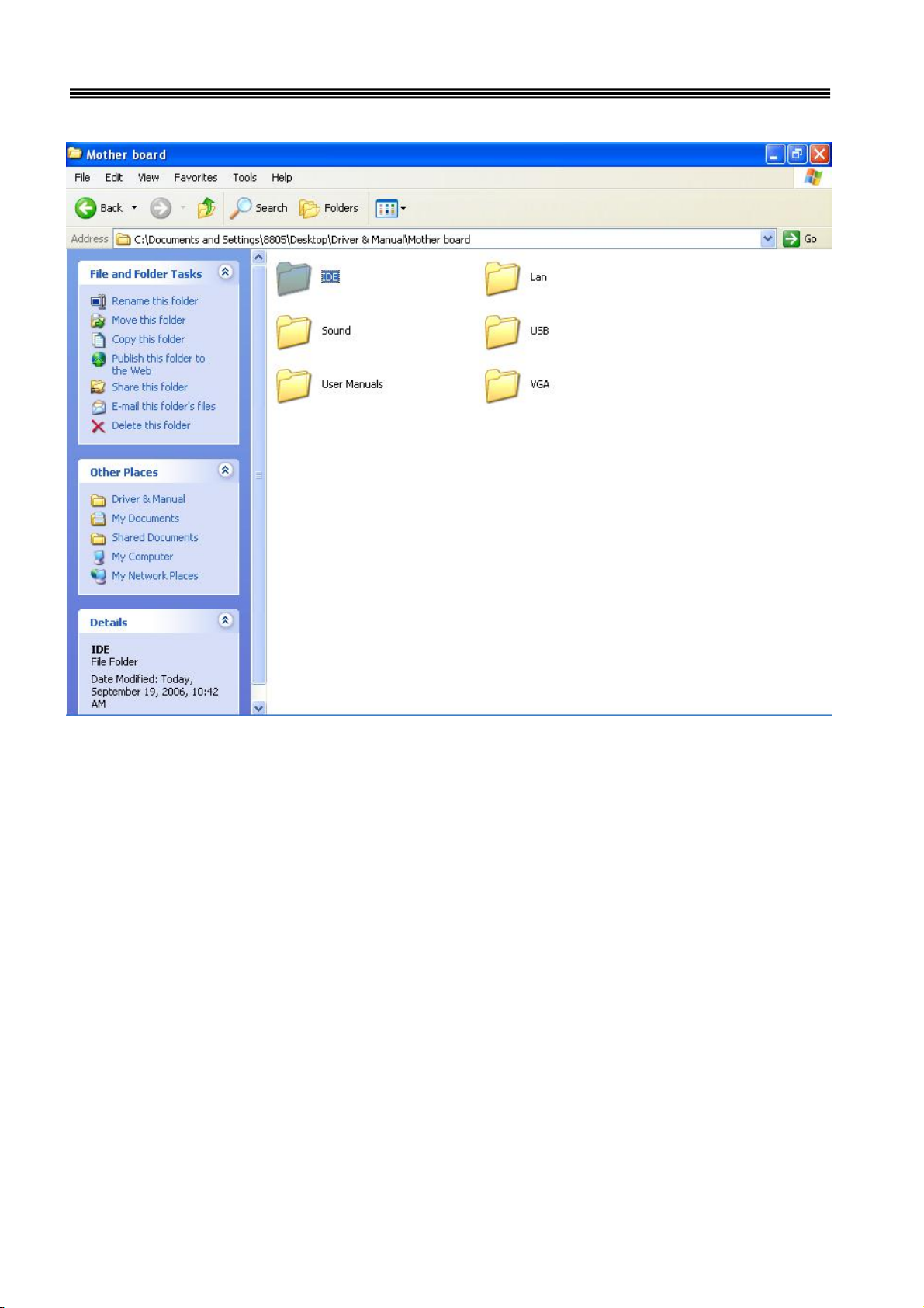
Select the "Mother board" folder.
24
8805 Touch POS User’s Manual
And select "IDE" folder.
25
8805 Touch POS User’s Manual
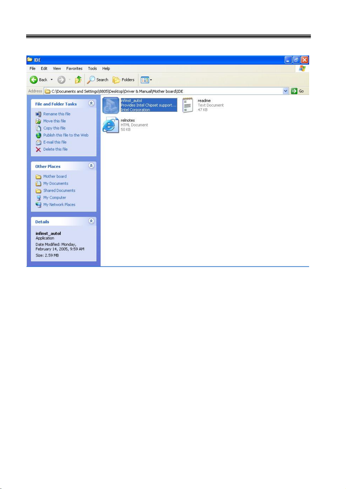
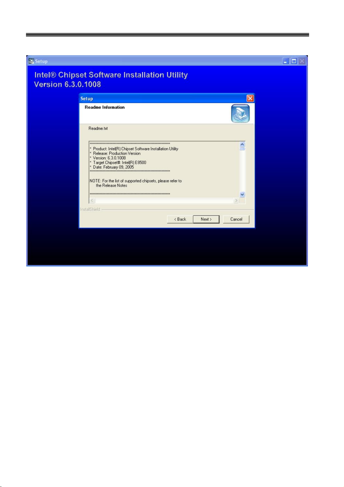
Access the "infinst_autol.exe".
26
8805 Touch POS User’s Manual
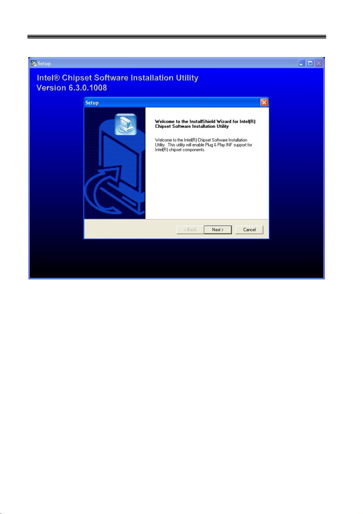
When the setup screen appears then to select "Next" step.
27
8805 Touch POS User’s Manual
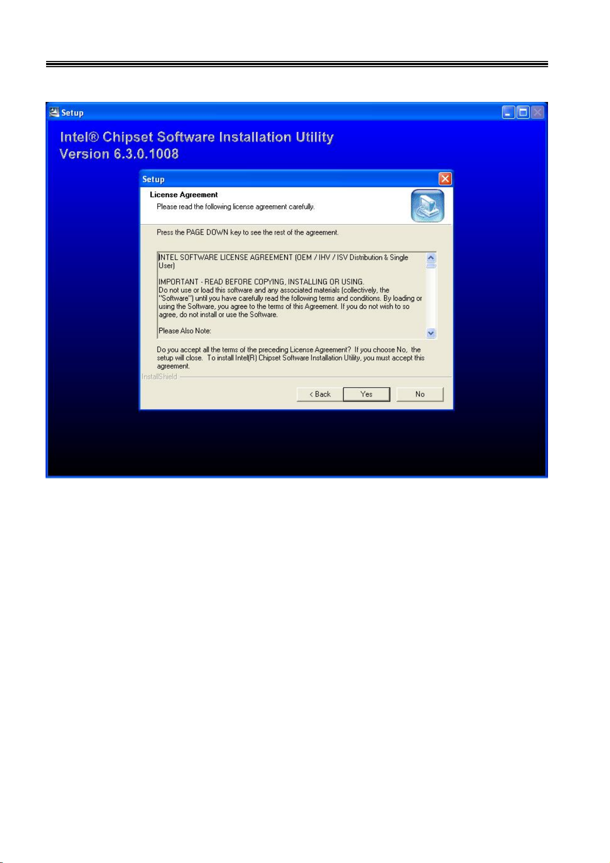
Select "Yes" to accept authorization agreement.
28
8805 Touch POS User’s Manual
Select "Next" step to accept the software understanding agreement.

29
8805 Touch POS User’s Manual
After installation
System will require reboot
select “YES”

30
8805 Touch POS User’s Manual
And select "IDE" folder.

31
8805 Touch POS User’s Manual
Select the "Mother board" folder.

32
8805 Touch POS User’s Manual
Select "Sound" folder.

33
8805 Touch POS User’s Manual
Access the "Setup".

34
8805 Touch POS User’s Manual
When the setup screen appears click the "Next" step.

35
8805 Touch POS User’s Manual
Above screen shows the setup process.

36
8805 Touch POS User’s Manual
After installation
System will require reboot
select “YES”

37
8805 Touch POS User’s Manual
LAN Drivers
Select "Mother board" folder.

38
8805 Touch POS User’s Manual
Select "LAN" folder.

39
8805 Touch POS User’s Manual
Access the "Setup".

40
8805 Touch POS User’s Manual
When the setup window appear then to select the "Next" step.

41
8805 Touch POS User’s Manual
When the next setup window appears again select the setup to continue the setup
process.

42
8805 Touch POS User’s Manual
Above screen shows the installation process window.

43
8805 Touch POS User’s Manual
After installation complete select “Finish”.

44
8805 Touch POS User’s Manual
VGA Drivers
Insert CD Rom and select "Driver & Manual" file folder.

45
8805 Touch POS User’s Manual
Select "Mother board" folder.

46
8805 Touch POS User’s Manual
Select "VGA" folder.

47
8805 Touch POS User’s Manual
Access "win2k_xp141950.exe".

48
8805 Touch POS User’s Manual
When setup window appear select the "Next" step.

49
8805 Touch POS User’s Manual
When next setup window appear select the "Next" step to continue setup.

50
8805 Touch POS User’s Manual
When setup window appear select the "Next" step.

51
8805 Touch POS User’s Manual
After installation
System will require reboot
select “YES”

52
Smart Card Reader Driver
Right click "My Computer" and select the "Properties".
8805 Touch POS User’s Manual
"

53
Select "Device Manager".
8805 Touch POS User’s Manual

54
Select "USB PC/SC Smart Card Reader" and right click to choose "Update
Driver".
8805 Touch POS User’s Manual

55
When the setup screen appears then to select "Advanced" & "Next" step.
8805 Touch POS User’s Manual

56
Select "Smartcard USB Driver" folder.
8805 Touch POS User’s Manual

57
8805 Touch POS User’s Manual
When next setup window appear select the "Next" step to continue setup.

58
When next setup window appear select the "Continue Anyway" step to continue
setup.
8805 Touch POS User’s Manual

59
Above screen shows the installation process window.
8805 Touch POS User’s Manual

60
After installation complete select “Finish”.
8805 Touch POS User’s Manual

61
Wi-Fi Driver
Right click "My Computer" and select the "Properties".
8805 Touch POS User’s Manual

62
Select "Device Manager".
8805 Touch POS User’s Manual

63
Select "USB2.0 WLAN" and right click to choose "Update Driver".
8805 Touch POS User’s Manual

64
When the setup screen appears then to select "Advanced" & "Next" step.
8805 Touch POS User’s Manual

65
Select Wi-Fi Driver folder.
8805 Touch POS User’s Manual

66
8805 Touch POS User’s Manual
When next setup window appear select the "Next" step to continue setup.

67
When next setup window appear select the "Continue Anyway" step to continue
setup.
8805 Touch POS User’s Manual

68
Above screen shows the installation process window.
8805 Touch POS User’s Manual

69
After installation complete select “Finish”.
8805 Touch POS User’s Manual

70
Mifare Driver
Select "USB-Serial Control" and right click to choose "Update Driver".
8805 Touch POS User’s Manual

71
When the setup screen appears then to select "Advanced" & "Next" step.
8805 Touch POS User’s Manual

72
Select "Mifare Driver" folder.
8805 Touch POS User’s Manual

73
8805 Touch POS User’s Manual
When next setup window appear select the "Next" step to continue setup.

74
When next setup window appear select the "Continue Anyway" step to continue
setup.
8805 Touch POS User’s Manual

75
Above screen shows the installation process window.
8805 Touch POS User’s Manual

76
After installation complete select “Finish”.
8805 Touch POS User’s Manual

77
Fingerprinter Driver
8805 Touch POS User’s Manual
Select "Fingerprinter" folder.

78
8805 Touch POS User’s Manual
Select "Pro Ws 3.5" folder.

79
8805 Touch POS User’s Manual
Access the "Setup".

80
8805 Touch POS User’s Manual
When the setup window appear then to select the "Next" step.

81
8805 Touch POS User’s Manual
When the setup window appear then to select the "I accept & Next" step.

82
8805 Touch POS User’s Manual
When the setup window appear then to select the "Next" step.

83
8805 Touch POS User’s Manual
When the setup window appear then to select the "Next" step.

84
8805 Touch POS User’s Manual
When the setup window appear then to select the "Next" step.

85
Above screen shows the installation process window.
8805 Touch POS User’s Manual

86
After installation complete select “Finish”.
8805 Touch POS User’s Manual

87
8805 Touch POS User’s Manual
After installation
System will require reboot
select “YES” .

88
8805 Touch POS User’s Manual
Commands for Peripheral
CHAPTER 4
Controlling
RS232 Protocol: 9600bps-N-8-1
Notice: Peripheral Control must be set up "COM3"
Follow the Jarltech standard command:
Send : <ESC> <Command code> <Length> <Data>
Response: <ESC> <Status code><length><data>
Note: 8805 controller return a beep after power on, delay about 3 sec then urn on the Main TFT Backlight, return another
beep and then start to receive the RS232 commands.
Read products Model Name
Command : <ESC><00h> Length & Data don’t need.
Response : <ESC><00h><07h><JP-8805>
Read Products Version info
Command : <ESC><01h> Length & Data don’t need.
Response: <ESC><01h> <Length depends on data ><8805 POS ……… V1.0 ….>
Beeps command:
Command : <ESC><22h> <01h><data>
<Data> = 00h ~ FFh , means how many beeps.
Response: <ESC><22h><01h><data>
Sound command:
Command : <ESC><24h> <02h><m><n>
m: tempo (ASCII DEC 1~255)
n: Frequency (ASCII DEC 1~255)
Response: <ESC><24h><02h><m><n>
Example:
<ESC><24h><02h><dec 2><dec 191> for play sound “Do“
Example Sound frequency Table:

89
8805 Touch POS User’s Manual
Do Re Mi Fa So La Si
G- : 255 A- : 227 B- : 202
C : 191 D : 170 E : 151 F : 143 G : 127 A : 113 B : 101
C+: 95 D+: 85 E+: 75 F+: 71 G+: 63 A+: 57 B+: 50
Open Cash Drawer Command :
Before send command, please confirm the S/W1 for provides voltage:
S/W1=OFF: 24V (default) S/W1=ON: 12V
The S/W2 is for setting auto response cash drawer sensor status after trigger cash drawer, or if someone manually to
open the cash drawer or close the cash drawer
Then controller will auto response status to software application.
.
S/W2=OFF: disable (d
Open Cash Drawer 1
Command : <ESC> + 34h (dec 52)
When S/W2=ON response: <ESC> + 34h (dec 52) + N
N = “A ” (41h, dec 65) , means Cash Drawer 1 is close.
N = “B” (42h, d ec 66) , means Cash Drawer 1 is open.
Open Cash Drawer 2
efault) S/W2=ON: Enable
Command : <ESC> + 35h (dec 53)
When S/W2=ON response: <ESC> + 35h (dec 53) + N
N = “A” (41h, dec 65), means Cash Drawer 2 is close.
N = “B” (42h, dec 66), means Cash Drawer 2 is open.
Detect Cash Drawer 1 Sensor
Command : <ESC> + 3Ah (dec 58)

90
8805 Touch POS User’s Manual
Response: <ESC> + 34h (dec 52) + N
N = “A” (41h, dec 65) , means Cash Drawer 1 is close.
N = “B” (42h, dec 66) , means Cash Drawer 1 is open.
Detect Cash Drawer 2 Sensor
Command : <ESC> + 3Bh (dec 59)
Response: <ESC> + 35h (dec 53) + N
N = “A” (41h, dec 65), means Cash Drawer 2 is close.
N = “B” (42h, dec 66), means Cash Drawer 2 is open.
Turn on the main TFT LCD backlight
Command : <ESC> + 38h (dec 56)
Turn off the main TFT LCD backlight
Command : <ESC> + 39h (dec 57)
Support Epson command to open the cash drawer:
1. [ESC] p m t1 t2
2. DLE DC4 n m t

91
8805 Touch POS User’s Manual
CHAPTER 5
5-1. COMPONENT LOCATIONS
Hardware Configuration
Placement Top View
170mm
170mm
(Dimensions: +/- 1mm)

92
8805 Touch POS User’s Manual
Bottom View

93
8805 Touch POS User’s Manual
Jumper Settings
To ensure correct system configuration, the following section describes how to set the jumpers to enable/disable or
change functions. For jumper descriptions, please refer to the table below.
Location Function
JP1 COM1 Signal / Power Se le ction
JP2 COM2 Signal / Power Se le ction
JP3 COM3 Signal / Power Se le ction
JP4 COM4 Signal / Power Se le ction
JP5 COM5 Signal / Power Se le ction
JP6 COM6 Signal / Power Se le ction
JP7 LPT1 Signal / Power Selection
JP8 CFD1 Master / Slave Selection
JP9 Clear CM OS Selection
JP10 LVDS Panel Power Selection
Table 2-1. Jumper Descriptions
JP1 - COM1 Signal/Power Selection (Pitch: 2.54mm):
Jumper Setting Fu nc t i on
1-3 Short Pin 1 of COM1 = +12V
1
9
2
10
1
2
Table 2-2. JP1 - COM1 Signal/Power Selection Settings
3-5 Short Pin 1 of COM1 = +5V
5-7 Short Pin 1 of COM1 = +5V
7-9 Short Pin 1 of COM1 = DCD
2-4 Short Pin 9 of COM1 = +12V
4-6 Short Pin 9 of COM1 = +5V
6-8 Short Pin 9 of COM1 = +5V
8-10 Short Pin 9 of COM1 = RI
JP2 - COM2 Signal/Power Selection (Pitch: 2.54mm):
Jumper Setting Fu nc t i on
1-3 Short Pin 1 of COM2 = +12V
3-5 Short Pin 1 of COM2 = +5V
1
9
2
10
1
2
5-7 Short Pin 1 of COM2 = +5V
7-9 Short
2-4 Short Pin 8 of COM1 = +12V
4-6 Short Pin 8 of COM1 = +5V
6-8 Short Pin 8 of COM1 = +5V
8-10 Short Pin 8 of COM1 = RI
Pin 1 of COM2 = DCD@RS232, TX+@RS422,
RTX+@RS485
Table 2-3. JP1 - COM2 Signal/Power Selection Settings

94
8805 Touch POS User’s Manual
JPx - COMx Signal/Power Selection (x = 3, 4, 5, 6 - Pitch: 2.54mm):
Jumper Setting Fu nc t i on
1-3 Short Pin 1 of COMx = +12V
1
9
2
10
1
2
Table 2-4. JP1 - COM3-6 Signal/Power Selection Settings
3-5 Short Pin 1 of COMx = +5V
5-7 Short Pin 1 of COMx = +5V
7-9 Short Pin 1 of COMx = DCD
2-4 Short Pin 8 of COMx = +12V
4-6 Short Pin 8 of COMx = +5V
6-8 Short Pin 8 of COMx = +5V
8-10 Short Pin 8 of COMx = RI
JP7 - LPT1 Signal/Power Selection (Pitch: 2.54mm):
Jumper Setting Function
1
9
2
10
1
2
3
1-2 Short Pin 4 of LPT1 = ERR#
1-3 Short Pin 4 of LPT1 = +5V
4-6 Short Pin 6 of LPT1 = +5V
5-6 Short Pin 6 of LPT1 = INIT#
7-8 Short Pin 8 of LPT1 = SLIN#
7-9 Short Pin 8 of LPT1 = +5V
Table 2-5. JP1 - LPT1 Signal/Power Selection
CF Master/Slave Selector (JP8: 3-pin 2.54mm pitch header):
Function JP1
Master 1-2 Short
Slave (Default) 2-3 Short
Table 2-6. CF Master/Slave Setting
Clear CMOS setting (JP9: 2-pin 2.54mm pitch header):
Function JP2
Normal (Default) Open
Clear CMOS Short
Table 2-7. Clear CMOS Setting
1
2

95
8805 Touch POS User’s Manual
Panel Power Selector (JP10: 3-pin 2.54mm pitch header):
Function JP3
+ 3.3 V (Default) 1-2 Short
+ 5 V 2-3 Short
Table 2-8. Panel Power Setting
Connector Pin Definitions
For Main Board connector and header descriptions, please refer to the table below.
Connector Function
ATX1 AT X Power Connector
CFD1 Compact Flash type I/II Connector
CN1 IrDA Pin Header
CN2 Digital Input / Digital Output Pin Header
CN3 SM Bus Wafer
CN6 Le f t Audi o AM P Output Waf er
CN7 LVDS Backlight Inverter Wafer
CN8 Right Audio AMP Output Wafer
COM2 RS-232 / 422 / 485 Port-2 Box Header
COM3 RS-232 Port-3 Box Header
COM4 RS-232 Port-4 Box Header
COM5 RS-232 Port-5 Box Header
COM6 RS-232 Port-6 Box Header
DIMM1 Primar y DDR SO-DIMM Socket
DIMM2 Secondary DDR SO-DIMM Socket
FAN1 FAN 1 Connector
FAN2 FAN 2 Connector
FAN3 FAN 3 Connector
FDD1 S lim Type Floppy Connector
FP1 Power LED Pin Header
FP2 Front Panel Pin Header
IDE1 Primar y 44-pin IDE Box Heade r
IDE2 Secondary 40-pin IDE Box Header
KB1 Internal PS/2 Keyboard Wafer
LVDS1 Channel 1 LVDS Connector
LVDS2 Channel 2 LVDS Connector
MPCI1 Mini-PCI Socket
MS1 Internal PS/2 Mouse Wafer
SW1 External PS/2 KB/MS Switch
USB1 USB Port-2&3 Box Header
USB2 USB Port-4&5 Box Header
Table 2-9. Main Board Connector and Header Descriptions

96
8805 Touch POS User’s Manual
ATX Power Connector (ATX1: 10x2 pin female):
PIN SIGNAL PIN SIGNAL
1 +3.3V 11 +3.3V
2 +3.3V 12 -12V
3 Ground 13 Ground
4 +5V 14 PS-ON
5 Ground 15 Ground
6 +5V 16 Ground
7 Ground 17 Ground
8 PW-OK 18 -5V
9 5VSB 19 +5V
10 +12V 20 +5V
Table 2-10. ATX Power Connector pin definition
CompactFlash slot (CFD1):
PIN SIGNAL PIN SIGNAL
1 GND 2 D3
3 D4 4 D5
5 D6 6 D7
7 CS0# 8 A10
9 ATASEL# 10 A9
11 A8 12 A7
13 VCC 14 A6
15 A5 16 A4
17 A3 18 A2
19 A1 20 A0
21 D0 22 D1
23 D2 24 IOCS16#
25 CD2 26 CD1
27 D11 28 D12
29 D13 30 D14
31 D15 32 CS1#
33 VS1 34 IORD#
35 IOWR# 36 WE#
37 INTRQ 38 VCC
39 CSEL# 40 VS2#
41 RESSET# 42 IORDY
43 INPACK# 44 REG#
45 DASP# 46 PDIAG#
47 D8 48 D9
49 D10 50 GND
Table 2-11. CompactFlash Slot pin definition

97
8805 Touch POS User’s Manual
IrDA Pin Header (CN1: 5x2-pin header 2.54mm pitch):
1
5
Pin Signal Name
1 +5V
2 NC
3 IRRX
4 GND
5 IRTX
Table 2-12. Digital I/O Pin Header pin definition
Digital I/O Pin Header (CN2: 5x2-pin header 2.54mm pitch):
PIN SIGNAL PIN SIGNAL
1 DO0 2 DI0
3 DO1 4 DI1
5 DO2 6 DI2
7 DO3 8 DI3
9 +5V 10 GND
Table 2-13. Digital I/O Pin Header pin definition
SMBus Wafer (CN3: 2x1-pin Wafer 2.0mm pitch):
1
3
5
7
9
2
4
6
8
10
Pin Status
1 SMDAT
2 SMCLK
Table 2-14. SMBus Header pin definition
Left Audio AMP Output Wafer (CN6: 2x1-pin Wafer 2.5mm pitch):
Pin Signal Name
1 Speaker+
2 Speaker-
Table 2-15. Left Audio AMP Output Header pin definition
LVDS Backlight Inverter (CN7: 7x1-pin Wafer 2.0mm pitch):
Pin Signal Name
1 +12V
2 +12V
3 +5V
4 GND
5 GND
6 Black Light Enable
7 Back Light Control
Table 2-16. LVDS Backlight Inverter Header pin definition

98
8805 Touch POS User’s Manual
Right Audio AMP Output Wafer (CN8: 2x1-pin Wafer 2.5mm pitch):
Pin S ignal Name
1 Speaker+
2 Speaker-
Table 2-17. Right Audio AMP Output Header pin definition
RS232/422/485 Serial Port Header (COM2: 5x2 box header 2.54mm pitch):
Pin Sign al
1 +5V / +12V /
RS-232:DCD, Data carrier detect
RS-422:TX+
RS-485:RTX+
Note:Selected by JP2
2 DSR, Data set ready
3 RS-232:RXD, Receive data
1
9 10
2
4 RTS, Request to send
5 RS-232:TXD, Transmit data
6 CTS, Cl ear to sen d
7
8 +5V / +12V / RI, Ring indicator
9 GND, ground
10 NC
RS-422:RX+
RS-485:N/A
RS-422:TXRS-485:RTX-
RS-232:DTR, Data terminal ready
RS-422:RXRS-485:N/A
Note:Selected by JP2
Table 2-18. COM2 RS232/422/485 Serial Port Header pin definition
RS232 Serial Port Header (COM3-6: 5x2 box header 2.54mm pitch):
1
9 10
Pin Signal
1 +5V / +12V / DCD, Data carrier detect
Note:Selected by JPx
2
2 DSR, Data set ready
3 RXD, Receive data
4 RTS, Request to send
5 TXD, Transmit data
6 CTS, Clear to send
7 DTR, Data terminal ready
8 +5V / +12V / RI, Ring indicator
9 GND, ground
10 NC
Table 2-19. COM3-6 RS232 Serial Port Header pin definition
Note:Selected by JPx
(x = 3, 4, 5, 6)

99
8805 Touch POS User’s Manual
Fan Connectors (Fan1-3: Wafer 2.54mm pitch):
PIN SIGNAL
1 RPM
2 +12V
3 GDN
Table 2-20. Fan Connectors pin definition
Power LED Pin Header 1 (FP1: 2x1-pin 2.54mm pitch):
1
2
Pin Status
1 Power LED +
2 Power LED -
Table 2-21. Power LED Pin Header 1 pin definition
Front Panel Pin Header 2(FP2: 5x2-pin 2.54mm pitch):
PIN SIGNAL PIN SIGNAL
1 H D D LED + 2 Power L ED +
3 HDD LED - 4 Power LED 5 Reset Swat c h - 6 Pow er Sw itch +
7 Reset Sw atch + 8 Power Switch 9 NC 10 Key
1
2
3
HDD_LED
RST_SW PWR_SW
1+
-
+
9
2
10
+
PWR_LED
-
+
-
Table 2-22. Front Panel Pin Header 2 pin definition
IDE1 Connector (IDE1: 22x2 box header 2.0mm pitch):
PIN SIGNAL PIN SIGNAL
1 Reset IDE 2 GND
3 IDE Data 7 4 IDE Data 8
5 IDE Data 6 6 IDE Data 9
7 IDE Data 5 8 IDE Data 10
9 IDE Data 4 10 IDE Data 11
11 IDE Data 3 12 IDE Data 12
13 IDE Data 2 14 IDE Data 13
15 IDE Data 1 16 IDE Data 14
17 IDE Data 0 18 IDE Data 15
19 Ground 20 NC
21 DREQ0 22 GND
23 IDEIOW# 24 GND
25 IDEIOR# 26 GND
27 IDEIORDY 28 CBSEL
29 DACK0# 30 GND
31 IDEIRQ14 32 NC
33 IDE Address 1 34 PDIAG#
35 IDE Address 0 36 IDE Address 2
37 IDE Chip select 1# 38 IDE Chip select 3#
39 IDE activity 40 GND
41 +5V 42 +5V
43 GND 44 NC
1
43
2
44
Table 2-23. IDE1 Connector pin definition
 Loading...