


ISO 9002 Certified
Lead with technology
Win customers with service
Customer Pole Display
MODEL 8034
OPERATION
MANUAL
1

2

© Jarltech International Inc. 1997. All rights reserved.
Under the copyright laws, this manual may not be copied, in
whole or in part, without the written consent of Jarltech.
Every effort has been made to ensure that the information in
this manual is accurate. Jarltech is not responsible for
printing or clerical errors.
Jarltech International Inc.
3F, No. 1, Lane 538, Chung Cheng Road, Hsin Tien,
Taipei, Taiwan, R.O.C.
ULTIMATE is a trademark of Ultimate Technology Corp.
EPSON is a trademark of Seiko Epson Corp.
ESC/P and ESC\POS are trademarks of Seiko Epson Corp.
3

4

This equipment has been tested and found to
comply with the limits for Class A digital device.
Pursuant to Part 15 of the FCC Rules. These limits
are designed to provide reasonable protection against
harmful interference in a residential installation.
This equipment generates, uses, and if not installed
and used in accordance with the instructions may
cause harmful interference will not occur in a
particular installation. If this equipment does cause
harmful interference to radio or television reception,
which can be determined by turning the equipment
off and on. The user is encouraged to try correct
interference by one or more of the following
measures:
- Reorient or relocate the receiving antenna.
- Increase the separation between the equipment and
receiver.
- Connect the equipment into an outlet on a circuit
different from that to which the receiver is
connected.
- Consult the dealer or an experienced radio/TV
technician for help. This booklet is available from
the U.S. government Printing Office, Washington,
DC 20402, Stock NO.004-000-00345-4.
CAUTION:
expressly approved by the grantee of this device could
void the user’s authority to operate the equipment.
Operation is subject to the following two conditions:
(1) This device may not cause harmful interference.
(2) This device must accept any interference received
including interference that may cause undesired
operation.
Any changes of modifications not
5

6

Contents
1. Before You Instal
2. Installing Model 8034
3. Programming Commands
4. Sample Program
Appendix I: Specifications
Appendix II:Select code table for ESC/POS
Appendix III:Code Table Selection
Appendix IV:The Code Table
7

8

1
Before You Install
• • • • • • •
This manual describes functions and usage of the
Jarltech Model 8034 customer pole display.
The 8034 is a 2x20 alphanumeric customer pole display
designed with multi-languages for retail and industrial
environments. Its outstanding features include high
quality vacuum fluorescent display in blue-green color,
RS232 interface, easy to use and powerful programming
features. The 8034 can also attach to any brand of serial
receipt printer.
Step 1: Turn Off Your Computer
By shutting off your computer, you will prevent any
accidental damage to the pole display and computer.
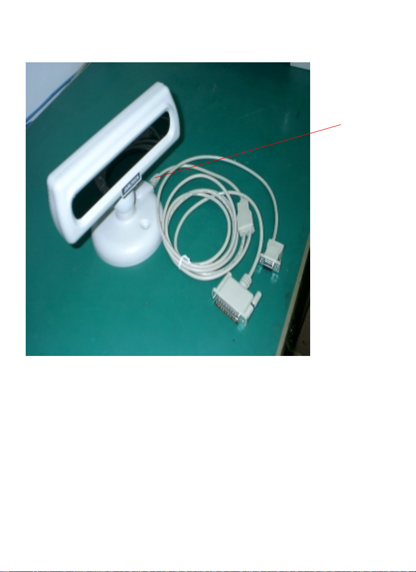
Step 2: Review Packing List
Please ensure that your pole display shipment is
complete.
Model 8034 includes:
• 1 pce 8034 pole display
• 1 pce operation manual
• 1 pce +12V DC power plate with internal power cable
(GC-POS-POWER)
• 1 pce DC cable (GC-RCA-DC)
• 1 pce Y cable (GC-8034YW)
• 1 pce pole
NOTE: The last character of "GC-8034YW" indecates
cable's color.
Ex: W=White; B=Black..
9

10

2
• • • • • • •
Installing Model 8034
This chapter describes the procedures for installing
the 8034 pole display by using RS232C interface.
Step 1: Turn off your computer
If you have not already done so, turn off your computer
to avoid any accidental damage to the pole display and
computer.
Step 2: Decide on baud rate, character set and command type
There are some functions such as baud rate, character
set and command type are selected by Dip switch. Please
refer to Appendix I: Specification to set the 8034 to meet
your requirement.
11
Installing Model 8034
Step 3: Bulid up your 8034
Plug into 8Pin
Phone Jack Socket
12
Step 4: Decide on power access
The RS232 connection requires power +12V DC. This
may be provided through an internal connection in your
computer or through an external connection to a 110/
220V adapter.
The components for an internal connection are provided.
If you are using an external connection, be sure that your
adaptor confirms with the specifications listed in Appendix I, then go to step 6.
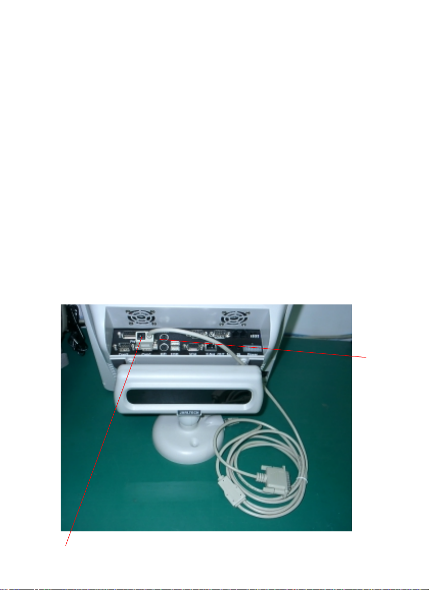
Step 5: Using internal power source
Refer to the installation diagram as below. Remove the
access cover to your computer. Mount the +12V DC
power plate on an available expansion slot in the back of
your computer. Attach the 4-pin male connector to the
open female connector of the same type in your computer.
Alternatively, an internal power source may be available
already if the 9-pin RS232 port on your computer or
terminal matches the 8034 pin assignment (see Specifications in Appendix I).
Installing Model 8034
Connect to 12V DC power
Connect to COM
Port
13
Installing Model 8034
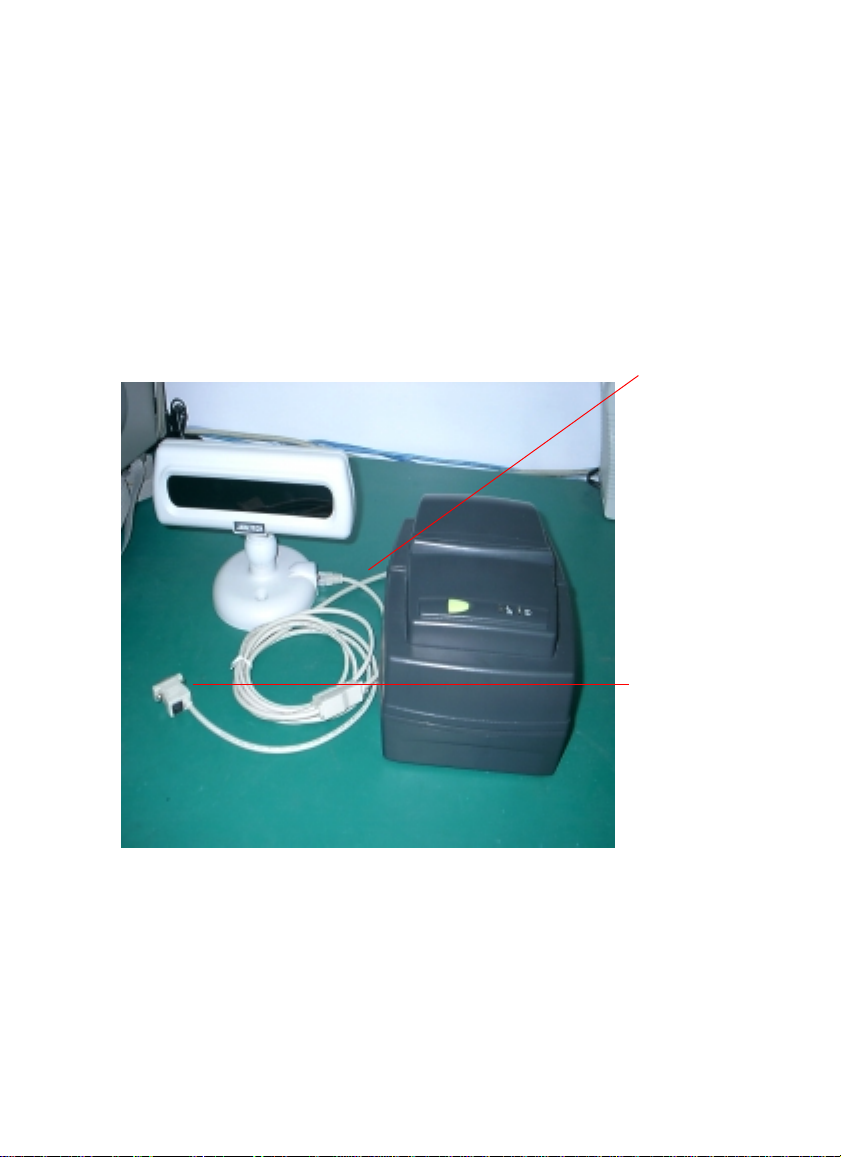
Step 6: Connect to printer
If you are not going to use 8034 pass through function,
please go to step 7. If you are using a serial printer to work
with 8034, please connect the Y cable (GC-8034YW) to
serial RS232 port, receipt printer and 8034 display.
(please refer to figure as below)
NOTE:
Please make sure the pinout of interface are matched between
receipt printer and DB-25M connector.
Serial port in printer interface
Serial port in RS232
Interface
Step 7: Connect to your computer
Connect the 9-pin female RS232 connector (DB9F with
DC jack) to the male equivalent (DB9M) RS232 port on
your computer or terminal. Provide power to the DC jack
on the DB9F connector using either a cable connection to
the +12V DC power plate or an external adapter.
14

Step 8: Turn on your computer
Turn on your computer. It should boot up normally.
The pole display will show a self-diagnostic status and
then the display will be blank.
Step 9: Turn to Chapter 3
You are now ready for operation, please refer to Chapter 3
for programming to meet the specific requirement of
your application environment.
Installing Model 8034
15

16

3
Programming Commands
• • • • • • •
Introduction
There are four programming modes available for model
8034 which are Jarltech mode, ESC/POS mode, UTC
standard mode and UTC w/pass through mode. In this
Chapter, we will always use Jarltech mode as an example
and the command codes for other modes, please refer to
Appendix II. For multi-languages, please refer to
Appendx III and IV for details.
The basic function of the 8034 display is comparable to
the display programming by your software should be as
easy. You just have to open the COM-port on which the
display has been connected by you. Then, you just send
the character you want the 8034 to display directly to the
COM interface. Please use the following RS232
parameters:
9600 Baud, No Parity, 8 Data Bits, 1 Stop bit
In Qbasic, you would initialize the interface as follows:
OPEN “COMx: 9600, N, 8, DS0” FOR OUTPUT AS #1
(x=number of the COM port you are using for the
display)
And you would print something to the display using the
PRINT command:
PRINT#1, “Hello World!”
In the end, you can close the interface:
CLOSE #1
In other programming languages, the commands for
serial output shall be different, but they will work in a
similar way. For some compilers, you will need an extra
toolbox, that offers you RS232 routines. Please refer to
your compiliers/interpreters manual for more details.
17

Programming Commands
Example:
OPEN “COM1: 9600, N, 8, 1, DS0” FOR OUTPUT AS
#1
PRINT #1, “Hello World!”
CLOSE #1
Programming using DOS routines
You can also generate a display output using the simple DOS
routines.
Example:
MODE COM1: 9600, N, 8, 1
ECHO Hello! >COM1:
Control characters and special functions
For special display functions, there are some commands which will
be explained in this chapter. Some of the commands consist of one
ASCII-CTRL-code, others are command strings, introduced by
ESC.
If a command needs additional parameters, please do not forget to use
ASCII format for the parameter. That means, if the parameter is 0
(zero), then you have to transmit the ASCII code “0” (=CHR$(48)
in Basic; 48 is the decimal position of the “0” character in the
ASCII code table). But please consider that only ONE byte is
allowed for each parameter. That is why you cannot transmit twodigit numbers. In this case, just add the number you want to
transmit as parameter 48 and transmit the corresponding character.
For example, if you want to transmit the parameter 11, you have to
send CHR$(11+48)=CHR$(59)=“;”. Attention: For some other
commands, only BYTE values are allowed as parameter. For those,
you directly send the corresponding character code without adding
48 (e.g. CHR$(11) for 11). For details, please refer to the individual
command code descriptions.
Example: Set the cursor to the last position in the display area
18

WRONG:
Programming Commands
PRINT #1, CHR$(27)+“=”; :REM command ESC =
PRINT #1, 19;1 :REM parameter column 19, line 1
CORRECT:
PRINT #1, CHR$(27)+“=”;
PRINT #1, CHR$(48+19)+“1” :REM or CHR$(48+19)+CHR$
(48+1)
Below is a list of command sequences for user to design an
interface to the JARLTECH 8034 customer pole display.
Please note that pole display is default with 9600 bps baud
rate, no parity, 8 data bits, 1 stop bit.
Jarltech command codes explanation(control sequences )
Note: They are with switch 7' 8 OFF(Refer Appendix I:Dip switch setting)
COMMANDS FUNCTION DESCRIPTION
Wrap mode
CTRL A
CTRL B
Turn on wrap mode
Code: 001
Turn off wrap mode
Code: 002
This allows the text
displayed to the screen
to wrap to the next line
when the cursor
position exceeds the
right handside
boundary. If autoscroll
is also on and the
cursor is on the bottom
line, the screen will
scroll up one row.
When the cursor
position meets the right
hand side boundary,
the cursor will not
continue. If any further
characters are received
then they will over write
the last character at the
right handside.
19

Programming Commands
COMMANDS FUNCTION DESCRIPTION
Cursor Move
CTRL H
CTRL J
CTRL V
CTRL K
Move cursor left
one column
Code: 008
Scroll (line feed)
Code: 010
Move cursor down
one row
Code: 022
Move cursor up one
row
Code: 011
This is simply the BACK
SPACE function, though
characters are not
deleted as you back
space over them. When
you reach the beginning
of a line, the cursor will
wrap to end of the
previous line until cursor
= 0,0 is met.
This is the LINE FEED
function. It will move
the cursor down one line.
It will always scroll the
screen if at the bottom.
This is an alternative
LINE FEED function
that will not scroll the
screen up one row when
at the bottom line.
This control sequence
will move the cursor up
one row. if it is at the top
of the screen, it will wrap
to the bottom line, the
cursor’s horizontal
location stays the same.
CTRL L
Move cursor right
one column
Code: 012
This is RIGHT ARROW
function. It will move
the cursor right by one
character cell. If it is at
the end of a line, the
cursor will wrap to the
next line until the bottom
right hand side is met.
20

Programming Commands
COMMANDS FUNCTION DESCRIPTION
CTRL M
Move cursor to
column 0
Code: 013
This is CARRIAGE
RETURN function
which returns the
cursor’s horizontal
location to the first
position, on the same
line.
NOTE:
In BASIC, after a PRINT#-command, a CR is always sent
to the display if you do not add an “; ” to the end of the
command. The CR command is normally used for the line
switching.
EXAMPLE:
PRINT #1, “First line!”
PRINT #1, CHR$(10);
PRINT #1, “Second line!”
CTRL ^
CTRL \
Cursor home
Code: 030
Reset
Reset display
Code: 028
This function will
return the cursor
position to 0,0.
This function will
execute a software
reset which will
initialize the entire
pole display. The
power up test will
begin as if power was
just switched on.
21

Programming Commands
COMMANDS FUNCTION DESCRIPTION
With the following commands, you can define up to 8
scrolling strings. Using another command, you can then
start and stop them in a certain display line. Your PC
does not have to care about this. The display does the
scrolling on its own until it receives the stop command.
Automatic Scrolling lines
ESC
PARAMETER FORMAT :
RANGES :
MESSAGE :
EXAMPLE :
ATTENTION :
ESC)
Program a message for the scrolling lines
Code: 027, 040
ESC ( <BLOCK><MESSAGE>
BLOCK : "1" - "8" (049 - 056)
Any text string terminated by 010,013
PRINT #1, CHR$(27)+“(1 This is scrolled”
Please do not forget to use ASCII format for the
parameters, so that for the text number, only the
codes 049-056 are allowed. Do not send 001008!
Start a line scrolling
Code: 027, 041
This function allows the
programmer to down
load 1 of 8 messages for
lines that you are going
to scroll.
These messages are 255
bytes long or can be
terminated by carriage
return, ENTER [010,
013].
This function starts one
of the total number of
lines, being (1 or 2),
scrolling horizontally.
You may specify the
direction, speed and
message.
22

Programming Commands
COMMANDS FUNCTION DESCRIPTION
PARAMETER FORMAT :
ESC ) <LINE> <DIRECTION> <SPEED>
<BLOCK_NO>
RANGES :
LINE : "0" (048) = first line
"1" (049) = second line
DIRECTION : "0" = right
"1" = left
SPEED : 0 to 16 (048-064).
BLOCK_NO : "1" to "8" (049-056)
EXAMPLE :
PRINT #1, CHR$(27) + ")0041" or PRINT #1,
CHR$(27)+CHR$(41)+CHR$(48)+CHR$(48)+CHR
(52)+CHR$(49)
This commands start the scrolling in the first line from
the left to the right with the speed 4 using the scrolling
text no.1 (as defined in the example above)
ESC %
PARAMETER FORMAT :
RANGES :
Stop a line from
scrolling
Code: 027, 037
ESC % <LINE>
LINE : “0”(048)=first line
“1”(049)=second line
This function will stop
one of the display rows
from scrolling its
message.
For further information
on scrolling message,
please refer to the
explanation on :
ESC ( : Program a
message for the
scrolling lines.
ESC ) : Start a line
scrolling.
23

Programming Commands
COMMANDS FUNCTION DESCRIPTION
Clear character
CTRL Z
or
ESC :
ESC !
ESC y
ESC Y
Home cursor, clear
characters to nulls
Code: 026
Code: 027, 058
Clear characters to
spaces
Code: 027, 033
Clear display to
spaces
Code: 027, 121
Clear from cursor to
end of the display
Code: 027, 089
This function will clear
all the characters to
blank character and
returns the cursor to 0,
0.
This function is the
same as CTRL Z & ESC
: , except that the
cursor position is not
changed
This function will clear
the entire screen to
spaces, but will not
change the character
attributes that are
associated to each
character.
This function is the
same as ESC T, except
that the screen will be
cleared to the bottom
right most boundary,
end of screen
ESC t
ESC T
Clear current line
to spaces
Code: 027,116
Clear from cursor to
the end of the line
Code: 027, 084
This function follows
the same rules as the
ESC y, except that
instead of clearing the
entire screen. This
function only clears the
current character line.
This function will clear
all characters to spaces,
on the current line,
from the current cursor
"X" to the end.
24

Programming Commands
COMMANDS FUNCTION DESCRIPTION
ESC R
Delete an entire
line
Code: 027, 082
Line Scroll
This function will
delete the current line
at cursor "Y" All data
below this line will
move up and the last
line will be blank.
ESC E
ESC j
ESC O
ESC N
Insert line of space
characters
Code: 027, 069
Move cursor up one
line (scroll if at top)
Code: 027, 106
Turn autoscroll on
Code: 027, 079
Turn autoscroll off
Code: 027, 078
This function will insert
a line of space characters at the current
vertical position. Data
on this line and underneath will scroll
downward.
This function will move
the cursor up 1 line, if
it is at the top of the
screen will scroll down
all the lines down, the
bottom line will be lost
and the top line will
become black.
This function enables
autoscrolling, which
simply means that
when the bottom right
most boundary is met,
the screen will scroll up
when the next printable
character is recieved.
This function will turn
off the autoscroll mode.
25

Programming Commands
COMMANDS FUNCTION DE S CR IP T IO N
ESC =
PARAMETER FORMAT :
RANGES :
EXAMPLE :
ATTENTION :
Set cursor position
Move cursor to X,Y
Code: 027, 061
ESC = <COLUMN X> <ROW Y>
COLUMN X : “0”-“19” (048-067).
ROW Y : “0”-“1” (048-049).
PRINT #1, CHR$(27)+“=11”;
Sets the cursor to the second line, second cell.
For all cursor move commands, please make sure
that your PRINT-command does not send a CR as
terminator, which will also change the cursor
position.
It will address the
cursor to an X, Y
location on display.
ESC_P
Printer functions
Enable printer,
disable display
Code: 027, 095, 080
If you have connected
both a serial printer and
8034 display on the same
COM port, you can use
this command to start
the access to the printer.
After power on, only the
display is active. If you
send ESC_P, the printer
mode will be activated,
all data sent to this
COM-port will be
printed and not
displayed.
26

Programming Commands
COMMANDS FUNCTION DESCRIPTION
ESC_D Disable printer,
enbale display
Code: 027, 095, 068
EXAMPLE:
PRINT #1, CHR$(27)+“*”;
PRINT #1,“Display”;
PRINT #1, CHR$(27)+“_P”
PRINT #1,“Printer is active.”+CHR$(13)
+CHR$(13)+CHR$(13)+CHR$(13)
PRINT #1, CHR$(27)+“_D”
PRINT #1, “again.”
Misc. cursor and VFD functions
ESC `
CTRL A
Turn cursor off
Code: 027,096,001
This command quits
the printer mode and
return to display mode.
The following data will
be displayed, not
printed.
This function is same
as ESC W, self explanatory
ESC ` C
TRL B
ESC `
CTRL G
ESC `
CTRL H
Turn cursor on
Code: 027,096,002
Turn VFD screen
off
Code: 027,096,007
Turn VFD screen
on
Code: 027,096,008
Self explanatory
Self explanatory
Self explanatory
27

Programming Commands
COMMANDS FUNCTION DESCRIPTION
ESC H
CTRL B
ESC H
CTRL C
You can define up to 16 function blocks (macros) with a
length of up to 127 byte. You can exceed the length of 127
bytes if you take care that you do not use the following
function block which would overwrite the data of the last
one.
ESC "
Turn on special
character mode
Code: 027,072,002
Turn off special
character mode
Code: 027,072,003
Macro programming
Program an
executable function block
Code: 027,034
The special character
mode allows you to use
the 8 user definable
characters, you also
must add DEC 32 or
Hex 20 to the
character.
Return the display to
normal display mode.
This function allows the
programmer to program a sequence of
function calls, control
or escape sequences
and even text.
The ability to execute
series of functions with
a single call is useful for
repetitive function
formats such as those in
the retail industry.
There are 16 usable
blocks all of which, if
you desire, may be
linked.
If you exceed the 127
byte size of the blocks,
the display will directly
link your block to the
next consecutive block.
28

Programming Commands
COMMANDS FUNCTION DESCRIPTION
This is only useful
upon power up,
because if you have
data in the next block,
its data will be
overwritten. Therefore
it is suggested these
blocks are unutilized
as one of the first steps
to use the display.
To link blocks, simply
add a function call,
from within a block, to
the block that you wish
to use.
PARAMETER FORMAT :
ESC “ <BLOCK-NO> <DATA and/or CTRL/
ESC SEQUENCES><ESC EOT>
RANGES :
BLOCK-NO : 0 - 15 (048 - 063)
ESC EOT: 027, 004.
EXAMPLE :
PRINT #1, CHR$(27)+CHR$(34)+“0”;
PRINT #1, CHR$(27)+“*”
PRINT #1, CHR$(27)+“Macro#0.”;
PRINT #1, CHR$(27)+CHR$(4)
ESC $
PARAMETER FORMAT :
RANGES :
Pause (for a
multiple of 8.88ms)
Code: 027,036
ESC $ <DELAY>
DELAY : 0 - 255 (000-255)(0 sec - 2.26 secs).
This function allows
the programmer to
stop the pole display
for a period
of time, The delay is in
multiple of 8.88ms.
29

Programming Commands
COMMANDS FUNCTION DESCRIPTION
ESC #
PARAMETER FORMAT :
RANGES :
EXAMPLE : Starts the Block-NO, that has been defined
Execute a programmed function
block
Code: 027,035
ESC # <BLOCK-NO>
BLOCK-NO : 0 - 31 (048 - 079)
in the example above.
PRINT #1, CHR$(27)+“#0”
This function allows the
programmer to call one
of the function blocks
for execution.
NOTE:
ESC_D
ESC_P
D&P must be capital initial.
Before you send commands, please make sure that you have
already connected printer to 8034. Otherwise you send
<ESC> <_> <P> <Hello> that will make your 8034 data
buffer full, but after you connect printer to 8034 it will work
normally.
To select to print
out the data from
display.
To select to print
out the data from
printer.
If you send<ESC>
<_> <D> <Hello>
then the pole display
will display “Hello”.
If you send <ESC>
<_> <P> <Hello>
then the printer will
print out “Hello”.
30

4
Sample Program
• • • • • • •
1 0 ’Sample program for Jarltech 8034 series
20 ’Copyright(C) Jarltech international INC. 1997
30 ’
40 RESET:CLEAR:SCREEN 0:COLOR 7,0:CLS
50 ’
60 OPEN “COM1:9600, N, 8, 1, CS0" AS #1
70 ’: Set RS232 Options
80 E$=CHR$(27)
90 ’: Set E$= "[ESC]"
10 0 ’Clear Screen & Set cursor off
110 PRINT #1,E$+":"+E$+"`"+CHR$(1)
120 ’
13 0 ’Demp program
140 ’
150 LOCATE 7,20:PRINT “Testing Jarltech 8004 Series..."
160 LOCATE 8,35:PRINT “[ESC] to Stop ..."
170 ’
18 0 ’Main **************************************
19 0 ’Program an Executable Function Block
200
’Syntax: ESC " <BLOCK><DATA and/or CTRL/ESC SEQUENCES> ESC <EOT>
210 ’Ranges:
22 0 ’ <BLOCK> : 00-31 (48 DEC - 79 DEC) ® ASCII: 0 ... O
23 0 ’ <EOT> : 04 DEC
240 ’
250 ED$=E$+CHR$(34) ‘: Set ED$= ESC "
260 EN$=E$+CHR$(4) ‘: Set EN$= ESC <EOT>
270 ’
2 80 PRINT #1,
2 9 0 PRINT #1,
3 00 PRINT #1,
3 10 PRINT #1,
3 2 0 PRINT #1,
330 PRINT #1,ED$+"5"+E$+"`"+CHR$(2)+EN$
340
PRINT #1,ED$+"6"+E$+"`"+CHR$(1)+CHR$(13)+"Turn LCD screen off"+EN$
ED$+"0"+CHR$(10)+CHR$(10)+CHR$(30)+CHR$(22)
ED$+"1"+CHR$(10)+CHR$(13)+"Testing Control ..."+EN$
ED$+"2"+CHR$(10)+CHR$(13)+"Command OK !"+EN$
ED$+"3"+CHR$(10)+CHR$(30)+"Testing [ESC] ..."+EN$
ED$+"4"+CHR$(22)+CHR$(13)"Cursor Off/On: "+EN$
31

350 PRINT #1,ED$+"7"+E$+"`"+CHR$(7)+EN$
360
PRINT #1,ED$+"8"+E$+"`"+CHR$(8)+CHR$(13)+"Turn LCD screen ON"+EN$
370 PRINT #1,ED$+"9"+E$+"`"+":"+"Move cursor :"CHR$(2)+EN$
380 PRINT #1,ED$+":"+E$+"B0"+EN$
390 PRINT #1,ED$+";"+E$+";1"+EN$
400 PRINT #1,ED$+"<"+E$+"=31"+EN$
410 ’
420 ’Excute Program Block
430 ’
440
FOR I=48 TO 61:PRINT #1,E$+"#"+CHR$(I):GOSUB 540:NEXT
450 PRINT #1,E$+"`"+CHR$(1)
460 ’
470 ’
Program a Message For the Scrolling Lines & Start a Line Scrolling
480 ’
490
PRINT #1,E$+";"+E$+"(1* Nice to see you! *"CHR$(13)+E$+")0091"
500
PRINT #1,E$+"(2* This is JARLTECH 8004 series DEMO *"+CHR$(13)+E$+")1192"
510 ’
520 END *************************************
530 ’
540 ’timer delay
550 T=INT(TIMER)
560 Y$=INKEY$:IF Y$=CHR$(27) THEN END
570 IF T+2 > TIMER THEN 560 ELSE RETURN
32


A
Appendix I
• • • • • • •
Specifications
Display
Case
Bottom Plate
Interface
Power
Requirement
• Type: alphanumeric dot matrix vacuum fluorescent
display
• Text mode: 20 characters x 2 lines
• Character size: 6.4(W) x 9.2mm(H), 5x7 dots
• Display color: blue green
• Brightness: 700 cd/m
• Dimension: 311mm(L) x 217mm(W) x 50mm(H)
• Adjustable angle: 270o swivl, 9o forward and 45o backward
• Pole height: 140mm
• Material: ABS
• ABS with metal plate. Screw holes available for pole
fixed
• RS232C
• RS232 interface: +12V DC directly from host or through
adaptor from external 110/220V AC source with polarity
as follows:
• Consumption: 4.5W
2
Programming
• More than 30 control sequences and escape sequences
for powerful programming such as move cursor, cursor
home, cursor blink, clear, delete, reset, scrolling,
program function block, pause, insert line and special
character mode.
34

8034 Specifications
8034 Y cable pinout
DB-9F DB-25M RJ-45 8P
Pin No. Signal Pin No. Singnal
-- -- -- 1 VCC
2 RX 2 -- - 5 GND 7 3 GND
9 -- -- -- --
-- -- 3 5 TX
6 DSR -- 6 RTS
8 CTS -- 6 RTS
3 TX -- 7 RX
-- -- 20 8 C T S
Dip Switch Setting Baud Rate
SWITCH FUNCTION
SW1 SW2 Baud Rate (bps)
OFF OFF 9600
ON OFF 1200
OFF O N 38400
ON O N 19200
Operation mode select
SWITCH FUNCTION
SW7 SW8 Operation Mode
OFF OFF Jarltech Command
ON OFF ESC/POS
OFF O N UTC standard
O N O N UTC W/pass through function
35

Dip Switch Setting
SW3 SW4 SW5 SW6
OFF OFF OFF OFF U.S.A PC-437
ON OFF OFF OFF FRANCE PC-850
OFF ON OFF OFF GERMANY PC-850
ON ON OFF OFF U.K. PC-850
OFF OFF O N OFF DENMARK I PC-850
ON OFF ON OFF SWEDEN PC-850
OFF O N O N OFF ITALY PC-850
O N ON O N OFF SPAIN PC-850
OFF OFF OFF ON JAPAN Katakana
ON OFF OFF ON NORWAY PC-850
OFF ON OFF ON DENMARK II PC-850
O N ON OFF ON SLAWIEN SLAWIEN
OFF OFF ON ON RUSSIA RUSSIA
ON OFF ON ON Reversed Reversed
OFF ON ON ON Reversed Reversed
O N ON O N O N USER DEFINE USER DEFINE
Specifications
International character set
SWITCH CHARACTER SET
International character Code table
ASCII code 20H-7FH ACSII code 80H-FFH
(USA standard Europe)
(multilingual)
See Table IV-2 and IV-3 for the international character set.
See Table IV-4 to IV-8 for the country code table.
36

A
• • • • • • •
The table indecates EPSON ESC/POS command list
Command Code description(Hex) Function
ESC t n 1B 74 n 0<=n<=7 Select code table (Refer Item I as
ESC R n 1B 52 n 0<=n<=12 Select international character set(Refer
I. Select code table for ESC/POS
n Code Table ASCII (80H~FFH)
0 PC437:U.S.A., standard Europe
1 Katakana for Japan
2 PC850: multilingual
3 PC860: Portuguese
4 PC863: Canadian-French
5 PC865: Nordic
Appendix II
bellow)
Item II)
(See table list in Appendix IV for more details.)
37

II. Set international character set for ESC/POS
International character set
n ASCII (20H~FFH)
0 U.S.A
1 FRANCE
2 GERMANY
3 U.K.
4 DENMARK I
5 SWEDEN
6 ITALY
7 SPAIN
8 JAPAN
9 NORWAY
10 DENMARK II
38

A
• • • • • • •
Appendix III
Code Table Selection
This chapter introduce you how to define/setup the font
table on the 8034 either through switch 3, 4, 5, 6 setting
or EEPROM programming.
The Switch Setting
Step 1: Turn off your computer
If you have not already done so, turn off your computer
to avoid any accidental damage to the pole display and
computer.
Step 2: Decide on the desired fonts
Please refer to the tables listed on Appendix IV to
decide which table is the one you are going to work on
the 8034. Adjust the switch 3, 4, 5, 6 (see Appendix I:
Specifications) for the correlative table.
Step 3: Connect 8034 to your computer
Connect the 9-pin female RS232 connector (DB9F with
DC jack) to the male equivalent (DB9M) RS232 port
on your computer or terminal. Provide power to the DC
jack on the DB9F connector using either a cable
connection to the +12V DC power plate or an external
adapter.
39

Code Table Selection
Step 4: Turn on your computer
Turn on your computer. It should boot up normally.
The pole display will show a self-diagnostic status and
then the display will be blank.
40

A
• • • • • • •
Appendix IV
HEX CODE HEX CODE
00H NULL 10H DL E
01H MD1 11H DC1
02H MD2 12H DC2
03H MD3 13H DC3
04H MD4 14H DC4
05H MD5 15H
06H MD6 16H
07H MD7 17H
08H BS,MD8 18H CAN
09H H T 19H
0AH LF 1AH
0BH H O M 1BH ESC
0CH CLR 1CH
0DH CR 1DH
0E H SLE1 1E H SF1
0FH RS,SLE2 1FH US,SF2
The Code Table
Table IV-1: Control code set
This is reserved by the 8034
41
The Code Table
International Characters Set
0123456789ABCDEF
..... ..O.. .O.O..O.O...O.. OO... .OO.. .OO.. ...O..O... ..... ..... ..... ..... ..... .....
..... ..O.. .O.O..O.O..OOOO O O..OO..O...O.. ..O.. ..O.. ..O.. ..O.. ..... ..... ..... ....O
..... ..O.. .O.O. OOOOO O .O.. ...O. O.O.. .O... .O... ...O. O.O.O ..O.. ..... ..... ..... ...O.
20h
..... ..O.. ..... .O.O..OOO...O.. .O... ..... .O... ...O..OOO. OOOOO ..... OOOOO ..... ..O..
..... ..... ..... OOOOO ..O.O .O... O.O.O ..... .O... ...O. O.O.O ..O.. .OO.. ..... ..... .O...
..... ..... ..... .O.O. OOOO. O..OO O..O. ..... ..O.. ..O.. ..O.. ..O.. ..O.. ..... .OO.. O....
..... ..O.. ..... .O.O...O.. ...OO .OO.O ..... ...O..O... ..... ..... .O... ..... .OO.. .....
.OOO...O.. .OOO. OOOOO ...O. OOOOO ..OO. OOOOO .OOO..OOO. ..... ..... ...O. ..... .O... .OOO.
O...O .OO.. O...O ...O...OO. O.... .O... ....OO...OO...O .OO.. .OO.. ..O.. ..... ..O.. O...O
O
..OO ..O.. ....O ..O.. .O.O. OOOO. O.... ...O. O...OO...O .OO.. .OO.. .O... OOOOO ...O. ....O
30h
O
.O.O ..O.. ...O. ...O. O..O. ....O OOOO...O.. .OOO..OOOO ..... ..... O.... ..... ....O ...O.
OO..O ..O.. ..O.. ....O OOOOO ....OO...O .O... O...O ....O .OO.. .OO.. .O... OOOOO ...O...O..
O...O ..O.. .O... O...O ...O. O...OO...O .O... O...O ...O..OO.. ..O.. ..O.. ..... ..O.. .....
.OOO..OOO. OOOOO .OOO. ...O..OOO..OOO..O... .OOO..OO.. ..... .O... ...O. ..... .O... ..O..
.OOO...O.. OOOO..OOO. OOO.. OOOOO OOOOO .OOO. O...O .OOO..OOOO O...OO.... O...OO...O .OOO.
O...O .O.O. O...OO...OO..O. O.... O.... O...OO...O ..O.. ...O. O..O. O.... OO.OO O...OO...O
O
.OOO O...OO...OO.... O...OO.... O.... O.... O...O ..O.. ...O. O.O.. O.... O.O.OOO..OO...O
40h
OO
.OO O...O OOOO. O.... O...O OOOO. OOOO. O.OOO OOOOO ..O.. ...O. OO... O.... O.O.OO.O.OO...O
O
.OOO OOOOO O...OO.... O...OO.... O.... O...OO...O ..O.. ...O. O.O.. O.... O...OO..OO O...O
O
.... O...OO...OO...OO..O. O.... O.... O...OO...O ..O.. O..O. O..O. O.... O...OO...OO...O
.OOOO O ...O OOOO..OOO. OOO.. OOOOO O.... .OOOO O...O .OOO..OO.. O...O OOOOO O...OO...O .OOO.
OOOO..OOO. OOOO..OOO. OOOOO O...OO...OO...OO...OO...O OOOOO .OOO. ..... .OOO...O.. .....
O...OO...OO...OO...O ..O.. O...OO...OO...OO...OO...O ....O .O... O.... ...O..O.O. .....
50h
O...OO...OO...OO.... ..O.. O...OO...OO...O .O.O..O.O. ...O..O... .O... ...O. O...O .....
OOOO. O...O OOOO..OOO...O.. O...OO...OO.O.O ..O.. ..O.. ..O.. .O... ..O.. ...O. ..... .....
O.... O.O.OO.O.. ....O ..O.. O...OO...OO.O.O .O.O...O.. .O... .O... ...O. ...O. ..... .....
O.... O..O. O..O. O...O ..O.. O...O .O.O. O.O.OO...O ..O.. O.... .O... ....O ...O. ..... .....
O.... .OO.OO...O .OOO...O.. .OOO...O.. .O.O. O...O ..O.. OOOOO .OOO. ..... .OOO. ..... OOOOO
..O.. ..... O.... ..... ....O ..... ...O. ..... O.... ..O.. ...O. O.... .OO.. ..... ..... .....
...O. ..... O.... ..... ....O ..... ..O.O ..... O.... ..... ..... O.... ..O.. ..... ..... .....
60h
..... .OOO. OOOO..OOOO .OOOO .OOO...O.. .OOOO OOOO..OO.. ...O. O..O...O.. OO.OO O.OO..OOO.
..... ....OO...OO.... O...OO...O .OOO. O...OO...O ..O.. ...O. O.O.. ..O.. O.O.OOO..OO...O
..... .OOOO O...OO.... O...O OOOOO ..O.. .OOOO O...O ..O.. ...O. OO... ..O.. O.O.OO...OO...O
..... O...OO...OO.... O...OO.... ..O.. ....OO...O ..O.. O..O. O.O.. ..O.. O.O.OO...OO...O
..... .OOOO OOOO..OOOO .OOOO .OOO...O.. OOOO. O...O .OOO..OO.. O..O..OOO. O...OO...O .OOO.
..... ..... ..... ..... ..O.. ..... ..... ..... ..... ..... ..... ..OO...O.. .OO.. .OO.O .....
..... ..... ..... ..... ..O.. ..... ..... ..... ..... ..... ..... .O... ..O.. ...O. O.OO. .....
70h
OOOO..OOOO O.OO..OOOO OOOOO O...OO...OO...OO...OO...O OOOOO .O... ..O.. ...O. ..... .....
O...OO...OOO..OO.... ..O.. O...OO...OO...O .O.O. O...O ...O. O.... ..... ....O ..... .....
OOOO..OOOO O.... .OOO...O.. O...OO...OO.O.O ..O.. .OOOO ..O.. .O... ..O.. ...O. ..... .....
O.... ....OO.... ....O ..O.OO...O .O.O. O.O.O .O.O. ....O .O... .O... ..O.. ...O. ..... .....
O.... ....OO.... OOOO. ...O..OOO...O.. .O.O. O...O OOOO. OOOOO ..OO...O.. .OO.. ..... .....
Table IV-2: U.S.A font set
Above U.S.A font set is acted as a basic font set. Only
ASCII 23H, 24H, 40H, 5BH, 5CH, 5DH, 5EH, 60H, 7BH,
7CH, 7DH and 7EH in Table IV-2 will be changed.
When you adjust the switch 3, 4, 5, 6 to select the international character.(refer to Table IV-3)
42

The Code Table
International 23 24 40 5B 5C 5D 5E 6 0 7B 7C 7D 7E
.O.O...O.. .OOO..OOO. ..... .OOO...O.. ..O.. ..OO...O.. .OO.. .OO.O
USA
FRANCE
GERMANY
U.K.
DENMARK I
SWEDEN
ITALY
SPAIN
JAPAN
NORWAY
DENMARK II
SLAWIEN
RUSSIA
.O.O..OOOO O...O .O... O.... ...O..O.O. ...O..O... ..O.. ...O. O.OO.
OOOOO O.O.. O.OOO .O... .O... ...O. O...O ..... .O... ..O.. ...O. .....
.O.O..OOO. OO.OO .O... ..O.. ...O. ..... ..... O.... ..... ....O .....
OOOOO ..O.OO.OOO .O... ...O. ...O. ..... ..... .O... ..O.. ...O. .....
.O.O. OOOO. O.... .O... ....O ...O. ..... ..... .O... ..O.. ...O. .....
.O.O...O.. .OOOO .OOO. ..... .OOO. ..... ..... ..OO...O.. .OO.. .....
.O.O...O.. .O... .OOO..OOOO .OOO...O.. ..O.. ...O..O... .O... .O.O.
.O.O..OOOO ..O.. .O.O. O.... O.... .O.O. ...O...O.. ..O.. ..O.. .....
OOOOO O.O.. .OOO..OOO. O.... .OOO. O...O ..... .OOO. ..... .OOO. .....
.O.O..OOO. ....O ..... O.... O...O ..... ..... O...OO...OO...O .....
OOOOO ..O.O .OOOO ..... .OOOO .OOO. ..... ..... OOOOO O...O OOOOO .....
.O.O. OOOO. O...O ..... ..O.. ....O ..... ..... O.... O..OO O.... .....
.O.O...O.. .OOOO ..... .O... .OOO. ..... ..... .OOO..OO.O .OOOO .....
.O.O...O.. .OOO. O...OO...OO...O ..O.. ..O.. .O.O. ..... ..... .OO..
.O.O..OOOO O.... ..... ..... ..... .O.O. ...O. ..... .O.O..O.O. O..O.
OOOOO O.O.. .OOO..OOO..OOO. O...OO...O ..... .OOO. ..... ..... OOO..
.O.O..OOO. O...OO...OO...OO...O ..... ..... ....O .OOO. O...OO..O.
OOOOO ..O.O .OOO. OOOOO O...OO...O ..... ..... .OOOO O...OO...OO..O.
.O.O. OOOO. ....OO...OO...OO...O ..... ..... O...OO...OO..OO OOO..
.O.O...O.. .OOO. O...O .OOO..OOO. ..... ..... .OOOO .OOO..OO.OO....
.O.O...O.. .OOO..OOO. ..... .OOO...O.. ..O.. ..OO...O.. .OO.. .OO.O
.O.O..OOOO O...O .O... O.... ...O..O.O. ...O..O... ..O.. ...O. O.OO.
OOOOO O.O.. O.OOO .O... .O... ...O. O...O ..... .O... ..O.. ...O. .....
.O.O..OOO. OO.OO .O... ..O.. ...O. ..... ..... O.... ..... ....O .....
OOOOO ..O.OO.OOO .O... ...O. ...O. ..... ..... .O... ..O.. ...O. .....
.O.O. OOOO. O.... .O... ....O ...O. ..... ..... .O... ..O.. ...O. .....
.O.O...O.. .OOOO .OOO. ..... .OOO. ..... ..... ..OO...O.. .OO.. .....
.O.O...O.. .OOO..OOOO ..O.. ..O.. ..O.. ..O.. ..... ..... ..O.. .OO.O
.O.O..OOOO O...OO.O.. .OOO..O.O..O.O. ...O. ..... ...O. ..... O.OO.
OOOOO O.O.. .OOO O.O.. O.O.O ..O.. O...O ..... OO.O..OOO..OOO. .....
.O.O..OOO. OO.OO O.OOO O.O.O .OOO. ..... ..... ..O.OO.O.O ....O .....
OOOOO ..O.OO.OOO OOO.. O.O.OO...O ..... ..... .OOOO O.O.O .OOOO .....
.O.O. OOOO. O.... O.O.. .OOO. OOOOO ..... ..... O.O.. .OOO. O...O .....
.O.O...O.. .OOOO O.OOO ..O.. O...O ..... ..... OO.OO .O... .OOOO .....
.O.O. O...O ...O..O.O..O.O..OOO..O.O. ...O..O.O. ..... .OOO. .....
.O.O..OOO...O.. ..... ..... .O.O. ..... ..O.. ..... .O.O..O.O..O.O.
OOOOO O...O OOOOO ..O.. .OOO..OOO. O...O .OOO..OOO. ..... .OOO. .....
.O.O. O...OO.... .O.O. O...OO...OO...OO...O ....O .OOO. ....OO...O
OOOOO O
...O OOOO. O...OO...O OOOOO O...O OOOOO .OOOO O...O .OOOO O ...O
.O.O..OOO. O.... OOOOO O...OO...OO...OO.... O...OO...OO...OO..OO
.O.O. O...O OOOOO O...O .OOO. O...O .OOO..OOO..OOOO .OOO..OOOO .OO.O
.O.O...O.. .OOO..OOO. ..... ...O...O.. .O... .O... .O... .O... .O...
.O.O..OOOO O...O .O.O. O .... ..O.. .O.O...O.. ..O.. ..O.. ..O.. ..O..
OOOOO O.O.. O.OOO .OOO..O... .OOO. O...O ..... .OOO. ..... .OOO. .....
.O.O..OOO. OO.OO ..... ..O.. O...O ..... O...O ....O .OOO. O...O .OO..
OOOOO ..O.OO.OOO ..... ...O. OOOOO ..... O...O .OOOO O...O OOOOO ..O..
.O.O. OOOO. O.... ..... ....OO.... ..... O..OO O...OO...OO.... ..O..
.O.O...O.. .OOOO ..... ..... .OOOO ..... .OO.O .OOOO .OOO..OOOO .OOO.
OOOO...O.. .OOO...O.. .OO.O ..O.. ..O.. ..O.. .O.O..OO.O .OO.. .OO.O
O
...O .OOOO O...O ..O.. O.OO. ..... .O.O. ...O. ..... O.OO. ...O. O.OO.
OOOO. O.O.. O.OOO ..... ..... ..O.. O...O ..... ..... ..... ...O. .....
O..O..OOO. OO.OO ..O.. OO..O .O... ..... ..... ..... O.OO. ....O .....
O.OOO ..O.OO.OOO ..O.. O.O.OO.... ..... ..... ..... OO..O ...O. .....
O..O. OOOO. O.... ..O.. O..OO O...O ..... ..... ..... O...O ...O. .....
O..OO ..O.. .OOOO ..O.. O...O .OOO. ..... ..... ..... O...O .OO.. .....
.O.O...O.. .OOO..OOO. O...O .OOO...O.. ..O.. ..OO...O.. .OO.. .OO.O
.O.O..OOOO O...O .O... .O.O. ...O..O.O. ...O..O... ..O.. ...O. O.OO.
OOOOO O.O.. O.OOO .O... OOOOO ...O. O...O ..... .O... ..O.. ...O. .....
.O.O..OOO. OO.OO .O... ..O.. ...O. ..... ..... O.... ..... ....O .....
OOOOO ..O.OO.OOO .O... OOOOO ...O. ..... ..... .O... ..O.. ...O. .....
.O.O. OOOO. O.... .O... ..O.. ...O. ..... ..... .O... ..O.. ...O. .....
.O.O...O.. .OOOO .OOO...O.. .OOO. ..... ..... ..OO...O.. .OO.. .....
.O.O. O...O ...O..OOOO ....O .OOO..O.O. ...O. ..... ..... .OOO..O.O.
.O.O..OOO...O.. O.O.. .OOO..O.O. ..... ..O.. ..... ...O..O.O. .....
OOOOO O...O OOOOO O.O.. O..OO .OOO. O...O .OOO. OO.O..OOO..OOO. .....
.O.O. O...OO.... O.OOO O.O.OO...OO...OO...O ..O.OO.O.O ....OO...O
OOOOO O
...O OOOO. OOO.. OO..O OOOOO O...O OOOOO .OOOO O.O.O .OOOO O...O
.O.O..OOO. O.... O.O.. .OOO. O...OO...OO.... O.O.. .OOO. O...OO..OO
.O.O. O...O OOOOO O.OOO O.... O...O .OOO..OOO. OO.OO .O... .OOOO .OO.O
.O.O...O.. ...O..OOOO ....O .OOO..O.O. ...O. ..... ..... .OOO..O.O.
.O.O..OOOO ..O.. O.O.. .OOO..O.O. ..... ..O.. ..... ...O..O.O. .....
OOOOO O.O.. OOOOO O.O.. O..OO .OOO. O...O .OOO. OO.O..OOO..OOO. .....
.O.O..OOO. O.... O.OOO O.O.OO...OO...OO...O ..O.OO.O.O ....OO...O
OOOOO
..O.O OOOO. OOO.. OO..O OOOOO O...O OOOOO .OOOO O .O.O .OOOO O...O
.O.O. OOOO. O.... O.O.. .OOO. O...OO...OO.... O.O.. .OOO. O...OO..OO
.O.O...O.. OOOOO O.OOO O.... O...O .OOO..OOO. OO.OO .O... .OOOO .OO.O
.O.O...O.. .OOO..OOO. ..... .OOO...O.. ..O.. ..OO...O.. .OO.. .OO.O
.O.O..OOOO O...O .O... O.... ...O..O.O. ...O..O... ..O.. ...O. O.OO.
OOOOO O.O.. O.OOO .O... .O... ...O. O...O ..... .O... ..O.. ...O. .....
.O.O..OOO. OO.OO .O... ..O.. ...O. ..... ..... O.... ..... ....O .....
OOOOO ..O.OO.OOO .O... ...O. ...O. ..... ..... .O... ..O.. ...O. .....
.O.O. OOOO. O.... .O... ....O ...O. ..... ..... .O... ..O.. ...O. .....
.O.O...O.. .OOOO .OOO. ..... .OOO. ..... ..... ..OO...O.. .OO.. .....
Table IV-3: ASCII CODE for internation character
43

The Code Table
0123456789ABCDEF
.OOOO ..... ...O...O.. .O.O..O... ..O.. ..... ..O.. .O.O..O... .O.O...O.. .O... .O.O...O..
O.... .O.O...O.. .O.O. ..... ..O.. .O.O..OOOO .O.O. ..... ..O.. ..... .O.O...O.. ..... .O.O.
80h
O.... ..... .OOO..OOO..OOO..OOO...O.. O.... .OOO..OOO..OOO...O.. ..... ..... .OOO...O..
O.... O...OO...O ....O ....O ....O .OOOO O.... O...OO...OO...O ..O.. ..O.. .OO.. O...O .OOO.
.OOOO O...O OOOOO .OOOO .OOOO .OOOO .OOOO .OOOO OOOOO OOOOO OOOOO ..O.. ..O.. ..O.. OOOOO O ...O
..O.. O..OO O.... O...OO...OO...OO...O ..O.. O.... O.... O.... ..O.. ..O.. ..O.. O...O OOOOO
.O... .OO.O .OOO..OOOO .OOOO .OOOO .OOOO .O... .OOOO .OOOO .OOOO ..O.. ..O.. .OOO. O...OO...O
...O. ..... .OOOO ..O.. .O.O..O... ..O.. .O... .O.O..O.O..O.O. ..... ..OO. O...O OOOO. ...O.
..O.. ..... O.O.. .O.O. ..... ..O.. .O.O...O.. ..... ..... ..... ...O..O..O .O.O. O...O ..O.O
90h
OOOOO OO
.O. O.O.. ..... ..... ..... ..... ..... O...O .OOO. O...O .OOOO .O... ..O.. OOOO...O..
O.... ..O.OO.OOO .OOO..OOO..OOO. O...OO...OO...OO...OO...OO.O.. OOOO. OOOOO O..O..OOO.
OOOO..OOOO OOO.. O...OO...OO...OO...OO...O .OOOO O...OO...OO.O.. .O... ..O.. O.OOO ..O..
O.... O.O.. O.O.. O...OO...OO...OO..OO O..OO ....OO...OO...O .OOOO .O... OOOOO O..O. O.O..
OOOOO OO.OO O.OOO .OOO..OOO..OOO..OO.O .OO.O OOOO..OOO..OOO..O... OOOOO ..O.. O..OO .O...
...O. ...O. ...O. ...O..OO.O .OO.O .OOO..OOO...O.. ..... ..... O..O. O..O...O.. ...O..O...
..O.. ..O.. ..O.. ..O.. O.OO. O.OO. ....OO...O ..... ..... ..... O.O.. O.O.. ..... ..O.OO.O..
A0h
.OOO. ..... ..... ..... ..... ..... .OOOO O...O ..O.. OOOOO OOOOO OO... OO..O ..O.. .O.O..O.O.
....O .OO.. .OOO. O...OO.OO. OO..OO...OO...O .O... O.... ....OO.OO. O..OO ..O.. O.O.. ..O.O
.OOOO ..O.. O...OO...OOO..OO.O.O .OOOO .OOO. O.... O.... ....O .O..O ..O.O ..O.. .O.O..O.O.
O...O ..O.. O...OO..OO O...OO..OO ..... ..... O...O ..... ..... ...O..OOOO ..O.. ..O.OO.O..
.OOOO .OOO..OOO..OO.OO...OO...O OOOOO OOOOO .OOO. ..... ..... .OOOO ....O ..O.. ...O..O...
.O.O. O.O.O OOOOO ..O.. ..O.. ..O.. .O.O. ..... ..... .O.O..O.O. ..... .O.O..O.O...O.. .....
O.O.O .O.O. OOOOO ..O.. ..O.. ..O.. .O.O. ..... ..... .O.O..O.O. ..... .O.O..O.O...O.. .....
B0h
.O.O. O.O.O OOOOO ..O.. ..O.. OOO.. .O.O. ..... OOO.. OO.O..O.O. OOOO. OO.O..O.O. OOO .. .....
O.O.O .O.O. OOOOO ..O.. OOO.. ..O.. OO.O. OOOO ...O.. ...O..O.O. ...O. ...O. OOOO...O.. OOO..
.O.O. O.O.O OOOOO ..O.. ..O.. OOO.. .O.O..O.O. OOO.. OO.O..O.O. OO.O. OOOO. ..... OOO .. ..O..
O.O.O .O.O. OOOOO ..O.. ..O.. ..O.. .O.O..O.O...O.. .O.O..O.O..O.O. ..... ..... ..... ..O..
.O.O. O.O.O OOOOO ..O.. ..O.. ..O.. .O.O..O.O...O.. .O.O..O.O..O.O. ..... ..... ..... ..O..
..O.. ..O.. ..... ..O.. ..... ..O.. ..O.. .O.O..O.O. ..... .O.O. ..... .O.O. ..... .O.O...O..
..O.. ..O.. ..... ..O.. ..... ..O.. ..O.. .O.O..O.O. ..... .O.O. ..... .O.O. ..... .O.O...O..
C0h
..O.. ..O.. ..... ..O.. ..... ..O.. ..OOO .O.O..O.OO .OOOO OO.OO OOOOO .O.OO OOOOO OO.OO OOOOO
..OOO OOOOO OOOOO ..OOO OOOOO OOOOO ..O.. .O.OO .O... .O... ..... ..... .O... ..... ..... .....
..... ..... ..O.. ..O.. ..... ..O.. ..OOO .O.O..OOOO .O.OO OOOOO OO.OO .O.OO OOOOO O O.OO OOOOO
..... ..... ..O.. ..O.. ..... ..O.. ..O.. .O.O. ..... .O.O. ..... .O.O..O.O. ..... .O.O. .....
..... ..... ..O.. ..O.. ..... ..O.. ..O.. .O.O. ..... .O.O. ..... .O.O..O.O. ..... .O.O. .....
.O.O. ..... ..... .O.O...O.. ..... ..... .O.O...O.. ..O.. ..... OOOOO ..... OOO .. ..OOO OOOOO
.O.O. ..... ..... .O.O...O.. ..... ..... .O.O...O.. ..O.. ..... OOOOO ..... OOO .. ..OOO OOOOO
D0h
.O.O. OOOOO ..... .O.O...OOO ..OOO .OOOO .O.O. OOOOO ..O.. ..... OOOOO ..... OOO.. ..OOO OOOOO
OOOOO
..... OOOOO .OOOO ..O.. ..O.. .O.O. OOOOO ..O.. OOO.. ..OOO OOOOO OOOOO OOO .. ..OOO OOOOO
..... OOOOO .O.O. ..... ..OOO ..OOO .O.O..O.O. OOOOO ..... ..O.. OOOOO OOOOO OOO.. ..OOO .....
..... ..O.. .O.O. ..... ..... ..O.. .O.O..O.O...O.. ..... ..O.. OOOOO OOOOO OOO.. ..OOO .....
..... ..O.. .O.O. ..... ..... ..O.. .O.O..O.O...O.. ..... ..O.. OOOOO OOOOO OOO.. ..OOO .....
....O ..OO. OOOOO OOOOO OOOOO ..OOO ..... ..... .OOO..OOO..OOO..OOOO ..... ....O .OOO..OOO.
....O .O..OO...O .O.O..O..O .O... O...O ..... .OOO. O...OO...OO.... .O.O. ...O. O.... O...O
E0h
.OO.O .OOO. O.... .O.O...O.. O.O.. O...O OOOOO O.O.OO...OO...O .O... O.O.O .OOO. O.... O...O
O
..O..O..OO.... .O.O. ...O. O..O. O..OO .O... O.O.O OOOOO O...O .OOO..O.O. O.O.O OOOO. O...O
O
..O..O..OO.... .O.O...O.. O...O OOO.O .O... O.O.OO...OO...OO...O ..... O.O.OO.... O...O
O
.O.O .OOO. O .... .O.O..O..OO..O. O.... .O... .OOO. O...O .O.O. O...O ..... .OOO. O.... O...O
OO
..OOO... O .... O..OO OOOOO .OO.. O.... ..OO..OOO..OOO. OO.OO .OOO. ..... O.... .OOO. O...O
..... O.... ....O ...O...O.. ..... .OO.O .OOO. ..... ..... .OOOO .O.O...OO. ..... .....
OOOOO
..... ..O.. .O... ...O...O.O ..O.. ..O.. O.OO..O.O. ..... ..... .O... .OO.O .O..O OOO.. .....
F0h
..... ..O.. ..O.. ..O.. ..O.. ..O.. ..... ..... .OOO..OO.. ..... .O... .O..O ...O. OOO.. .....
OOOOO OOOOO ...O..O... ..O.. ..O.. OOOOO .OO.O ..... .OO.. ..O.. .O... .O..O ..O.. OOO.. .....
..... ..O.. OOOOO OOOOO ..O.. ..O.. ..... O.OO. ..... ..... ..... .O... ..... .OOOO OOO.. .....
..... ..O.. ..... ..... ..O.. O.O.. ..O.. ..... ..... ..... ..... OO... ..... ..... OOO.. .....
OOOOO OOOOO OOOOO OOOOO ..O.. .O... ..... ..... ..... ..... ..... .O... ..... ..... ..... .....
Table IV-4: PC-437 U.S.A. and Standard Europe code table
0123456789ABCDEF
.OOOO .O.O. ...O...O.. .O.O..O... ..O.. ..... ..O.. .O.O..O... .O.O...O.. .O... .O.O...O..
O.... ..... ..O.. .O.O. ..... ..O.. .O.O..OOOO .O.O. ..... ..O.. ..... .O.O...O.. ..... .O.O.
80h
O.... O...O .OOO..OOO..OOO..OOO...O.. O.... .OOO..OOO..OOO...O.. ..... ..... .OOO...O..
O.... O...OO...O ....O ....O ....O .OOOO O.... O...OO...OO...O ..O.. ..O.. .OO.. O...O .OOO.
.OOOO O ...O OOOOO .OOOO .OOOO .OOOO .OOOO .OOOO OOOOO OOOOO OOOOO ..O.. ..O.. ..O.. OOOOO O...O
..O.. O..OO O.... O...OO...OO...OO...O ..O.. O.... O.... O.... ..O.. ..O.. ..O.. O...O OOOOO
.O... .OO.O .OOOO .OOOO .OOOO .OOOO .OOOO .O... .OOO..OOO..OOO...O.. ..O.. .OOO. O...OO...O
...O. ..... .OOOO ..O.. .O.O..O... ..O.. .O... .O.O..O.O..O.O. ..... ..OO. ...O. ..... ...O.
..O.. ..... O.O.. .O.O. ..... ..O.. .O.O...O.. ..... ..... ..... ...O..O..O .OOO. O...O ..O.O
90h
OOOOO OO
.O. O.O.. ..... ..... ..... ..... ..... O...O .OOO. O...O .OOO..O... O.O.O .O.O...O..
O.... ..O.OO.OOO .OOO..OOO..OOO. O...OO...OO...OO...OO...OO.O.O OOOO. O.O.O ..O.. .OOO.
OOOO..OOOO OOO.. O...OO...OO...OO...OO...O .OOOO O...OO...OO.O.O .O... O.O.O .O.O...O..
O.... O.O.. O.O.. O...OO...OO...OO..OO O..OO ....OO...OO...O .OOO..O... .OOO. O...OO.O..
OOOOO OO.OO O.OOO .OOO..OOO..OOO..OO.O .OO.O OOOO..OOO..OOO..O... OOOOO .O... ..... .O...
...O. ...O. ...O. ...O..OO.O .OO.O .OOO..OOO...O.. .OOO. ..... O..O. O..O...O.. ...O..O...
..O.. ..O.. ..O.. ..O.. O.OO. O.OO. ....OO...O ..... OOO.O ..... O.O.. O.O.. ..... ..O.OO.O..
A0h
.OOO. ..... ..... ..... ..... ..... .OOOO O...O ..O.. OO.OO OOOOO OO... OO..O ..O.. .O.O..O.O.
....O .OO.. .OOO. O...OO.OO. OO..OO...OO...O .O... OOO.O ....OO.OO. O..OO ..O.. O.O.. ..O.O
.OOOO ..O.. O...OO...OOO..OO.O.O .OOOO .OOO. O.... OOO.O ....O .O..O ..O.O ..O.. .O.O..O.O.
O...O ..O.. O...OO..OO O...OO..OO ..... ..... O...OOO.OO ..... ...O..OOOO ..O.. ..O.OO.O..
.OOOO .OOO..OOO..OO .OO...OO...O OOOOO OOOOO .OOO..OOO. ..... .OOOO ....O ..O.. ...O..O...
.O.O. O.O.O OOOOO ..O.. ..O.. ...O...O.. .O... .OOO..O.O..O.O. ..... .O.O...O.. O...O .....
O.O.O .O.O. OOOOO ..O.. ..O.. ..O.. .O.O...O.. O...O .O.O..O.O. ..... .O.O..OOOO .O.O. .....
B0h
.O.O. O.O.O OOOOO ..O.. ..O.. ..... ..... ..... O.OOO OO.O..O.O. OOOO. OO.O. O.O.. ..O.. .....
O.O.O .O.O. OOOOO ..O.. OOO.. .OOO..OOO..OOO. OO..O ...O..O.O. ...O. ...O. O.O.. OOOOO OOO..
.O.O. O.O.O OOOOO ..O.. ..O.. O...OO...OO...OO.OOO OO.O..O.O. OO.O. OOOO. O.O.. ..O.. ..O..
O.O.O .O.O. OOOOO ..O.. ..O.. OOOOO OOOOO OOOOO O ...O .O.O..O.O..O.O. ..... .OOOO OOOOO ..O..
.O.O. O.O.O OOOO ..O.. ..O.. O...OO...OO...O .OOO..O.O..O.O..O.O. ..... ..O.. ..O.. ..O..
..O.. ..O.. ..... ..O.. ..... ..O.. .OO.O .OO.O .O.O. ..... .O.O. ..... .O.O. ..... .O.O. O...O
..O.. ..O.. ..... ..O.. ..... ..O.. O.OO. O.OO..O.O. ..... .O.O. ..... .O.O. ..... .O.O..OOO.
C0h
..O.. ..O.. ..... ..O.. ..... ..O.. ..... ..... .O.OO .OOOO OO.OO OOOOO .O.OO OOOOO O O.OO O...O
..OOO OOOOO OOOOO ..OOO OOOOO OOOOO .OOOO .OOO..O... .O... ..... ..... .O... ..... ..... O...O
..... ..... ..O.. ..O.. ..... ..O.. .OOOO O...O .OOOO .O.OO OOOOO OO.OO .O.OO OOOOO OO.OO O...O
..... ..... ..O.. ..O.. ..... ..O.. O...O OOOOO ..... .O.O. ..... .O.O..O.O. ..... .O.O..OOO.
..... ..... ..O.. ..O.. ..... ..O.. .OOOO O...O ..... .O.O. ..... .O.O..O.O. ..... .O.O. O...O
.O.O. OOOO..O... .O.O. ...O..OO.. ...O...O.. ..... ..O.. ..... OOOOO ..... ..O.. .O... OOOOO
OOO
D0h
E0h
F0h
.. .O..O ..O.. ..... ..O.. ..O.. ..O.. .O.O..O.O...O.. ..... OOOOO ..... ..O.. ..O.. OOOOO
...O..O..O OOOOO OOOOO OOOOO ..O.. ..... ..... ..... ..O.. ..... OOOOO ..... ..O.. ..... OOOOO
.OOO. OOO.OO.... O.... O.... ..O.. .OOO..OOO..OOO. OOO.. ..OOO OOOOO OOOOO ..... .OOO. OOOOO
O
...O .O..O OOOO. OOOO. OOOO...O.. ..O.. ..O.. ..O.. ..... ..O.. OOOOO OOOOO ..O.. ..O.. .....
O...O .O..OO.... O.... O.... ..O.. ..O.. ..O.. ..O.. ..... ..O.. OOOOO OOOOO ..O.. ..O.. .....
.OOO. OOOO. OOOOO OOOOO OOOOO .OOO..OOO..OOO..OOO. ..... ..O.. OOOOO OOOOO ..O.. .OOO. .....
...O...OO...O.. .O... .OO.O .OO.O .O..O .O... OOO.. ...O...O.. .O... ...O. ...O. OOOOO ...O.
..O.. .O..O .O.O...O.. O.OO. O.OO..O..O .OOO..OOO...O.. .O.O...O.. ..O.. ..O.. ..... ..O..
.OOO..OOO. ..... .OOO. ..... ..... .O..O .O..O .O..O ..... ..... ..... O...OO...O ..... .....
O...O .O..O .OOO. O...O .OOO..OOO..OOO..O..O .O..OO...OO...OO...OO...OO...O ..... .....
O...O .O..OO...OO...OO...OO...O .O... .OOO..OOO. O...OO...OO...O .OOOO .O.O. ..... .....
O...O .OOO. O...OO...OO...OO...O .O... .O... .O... O...OO...OO...O ....O ..O.. ..... .....
.OOO. OO... .OOO..OOO..OOO..OOO. O.... .O... OOO.. .OOO..OOO..OOO. OOOO...O.. ..... .....
OOOOO ..... ..... OO... .OOOO .OOO. ..... ..... .OOO..O.O. ..... ..O.. .OOO...OO. ..... .....
..... ..O.. ..... ..O.. OO.O. O.... ..O.. ..... .O.O. ..... ..... .OO.. ....O .O..O OOO.. .....
..... ..O.. OOOOO OOO.. .O.O..OOO. ..... O.OO..OOO. ..... ..OO...O.. ..OO. ...O. OOO.. .....
..... OOOOO ..... ..O.O .O.O. O...O OOOOO .OOO. ..... ..... ..OO...O.. ....O ..O.. OOO.. .....
..... ..O.. OOOOO OO.OO .O.O..OOO. ..... ..... ..... ..... ..... .OOO..OOO..OOOO OOO.. .....
..... ..O.. ..... ..OOO .O.O. ....O ..O.. ..... ..... ..... ..... ..... ..... ..... OOO.. .....
..... OOOOO ..... ....OO..O..OOO. ..... ..... ..... ..... ..... ..... ..... ..... ..... .....
Table IV-5: PC-850 multingual code table
44

The Code Table
0123456789ABCDEF
....O ..OO. O.OO. ..... .OOO. O.OO..OOO. ..... OO..O OOOOO .OOO...OOO OOOOO ..O.. .OOO. OOOOO
....O .O..O .O..O ....OO...O .O..OO...OO.... OO..O .O.O. O...O .O... ...O..OOO. O...O .O..O
80h
.OO.O .OOO..O... ...OO O.... .O..OO...O .O... OO..O .O.O. OO..O .OOO...O.. O.O.OO...O ..O..
O..O..O..O .O... ..O.O OOOO..O..O OOOOO ..O.. O.OO..O.O. O.OO. O...O .O... O.O.OO...O ...O.
O..O..O..O .O... .O..OO.... ....OO...O .O.O. O.... .O.O. O.... O...O .O... .OOO. O...O ..O..
O.O.O .OOO..O... O...OO...O ....OO...OO...OO.... .O.O. O.... O..O...O.. ..O.. .O.O..O..O
OO
..OOO... OO ... OOOOO .OOO. ....O .OOO. O...OO.... O..OO O.... .OO.. ...O...O.. OO.OO OOOOO
..OO..OOOO OOOOO OOOO. ...O. OOOOO ..... ....O ..OO..OOO..O..OO...O .O... .OOOO ..O.. .....
.O..OO.... OO... OO..O ..O.. ..... ..O.. ....O .O..O ....O ..OO. O..O..O..O .O... ..O.. .....
90h
.O... .OOO. OO... OO..O ..O.. O...O ..... OOO.O ...O...OO...OO. O.O.. .O.O..O... OOOOO .OOO.
OOO.. O...O OOOOO OOOO...O.. .O.O..OOO. ....O ..O.. ....O .O..O .O... ..O.. .O... ..O.. .OOO.
.O... .OOO. OO... OOO.. ..O.. ..O.. .O.O. ....O .OOOO .OOO. ..... O.OOO .O... .O... ..O.. .OOO.
.O... ....OOO... OO.O...O.. .O.O..OOO. ..... ..... ..... ..... ...O. O.... OO... ..... .....
OOOOO OOOO. OOOOO OO..O .O... O ...O .O.O. ..... ..... ..... ..... ..OOO ..... .O... OOOOO .....
..... ..... ..OOO ..... ..... ..... ..... ..... ..... ..... ..... ..... ..... ..... ..... .....
..... ..... ..O.. ..... ..... ..... OOOOO ..... ....O ..... ..... ..... ..... ..... ..... .....
A0h
..... ..... ..O.. ..... ..... ..... ....O OOOOO ...O...O.. ..... ...O..O... ..... OOOO. .....
..... ..... ..O.. ..O.. ..... .OO.. OOOOO ....O ..O.. OOOOO OOOOO OOOOO OOOOO .OOO. ...O. O.O.O
..... OOO.. ..... ..O.. O.... .OO.. ....O ..OO..OO.. O...O ..O.. ..OO..O..O ...O. OOOO. O.O.O
..... O.O.. ..... ..O.. .O... ..... ...O...O.. O.O.. ....O ..O.. .O.O..O.O. ...O. ...O. ....O
..... OOO.. ..... OOO.. ..O.. ..... ..O.. .O... ..O.. ..OO. OOOOO O..O..O... OOOOO OOOO...OO.
..... OOOOO ....O ..O.. ..... ...O..O... ..O.. ..... .O... ..... .O.O. ..... ..... .O... .....
..... ....O ...O. OOOOO OOOOO OOOOO OOOOO OOOOO .OOOO .OOOO OOOOO OOOOO OO... OOOOO OOOOO O...O
B0h
..... ..O.O ..O.. O...O ..O.. ...O..O..O ..O.. .O..OO..O. ....O .O.O. ....O ....O .O..OO...O
OOOOO
..OO..OO.. O...O ..O.. ..OO..O..O OOOOO O...O ...O. ....O .O.O. OO..O ...O..O.O..O..O
..... ..O.. O.O.. ....O ..O.. .O.O..O..O ..O.. ....O ...O. ....O ...O. ....O ..O.. .O... ....O
..... ..O.. ..O.. ...O...O.. O..O..O..O ..O.. ...O. ...O. ....O ..O.. ...O..O.O..O... ...O.
..... .O... ..O.. ..O.. OOOOO ...O. O..O...O.. .OO.. ..O.. OOOOO .O... OOO.. O...O ..OOO .OO..
..... ...O. ..... .OOO..O... ..O.. ..... ..... ..O.. ...O. ..... O.... ..... ..... ..O.. .....
.OOOO OOO.. O.O.O ..... .O... ..O.. .OOO. OOOOO OOOOO ...O...O.. O.... OOOOO .O... OOOOO OOOOO
C0h
.O..O ..O.. O.O.O OOOOO .O... OOOOO ..... ....O ...O. ...O. ...O. OOOOO ....OO.O.. ..O.. ....O
O
.O.O OOOOO O.O.O ..O.. .OO.. ..O.. ..... .O.O...O.. ...O. O...OO.... ....O ...O...O.. ....O
...OO ..O.. ....O ..O.. .O.O...O.. ..... ..O.. .OOO. ...O. O...OO.... ....O ....OO.O.O .O.O.
...O...O.. ...O...O.. .O... .O... ..... .O.O. O.O.O ..O.. O...OO.... ...O. ....OO.O.O ..O..
.OO.. .O... ..O.. .O... .O... O.... OOOOO O.... ..O.. .O... O...O .OOOO .OO.. ..... ..O.. ...O.
..... ..... ..... ..... .O... ..... ..... .OOO. O...O ..... ..... ..... ..... ..... ..O.. OOO..
.OOO...O.. ....O OOOOO .O... .OOO. OOOOO ..... O ...O ..O.. O.... OOOOO OOOOO OO... O..O. O.O..
D0h
..... .O... ....O .O... OOOOO ...O. ....O OOOOO O...OO.O.. O.... O...OO...O ....O .O... OOO..
.OOO. O.... .O.O. OOOOO .O..O ...O. OOOOO ....OO...OO.O.. O...OO...O ....O ....O ..... .....
..... O...O ..O.. .O... .O.O. ...O. ....O ....O ....OO.O.OO..O. O ...O ....O ....O ..... .....
OOOO. OOOOO .O.O..O... .O... ...O. ....O ...O. ...O. O.O.OO.O.. O...O ...O. ...O. ..... .....
....O ....OO.... ..OOO .O... OOOOO OOOOO ..O.. ..O.. O.OO. OO... OOOOO ..O.. OOO.. ..... .....
..O.. ..O.. ..... ..... ....OO.... ..O.. ..O.. O.... ....O .O.O...O.O ...O..O... ..... .....
.OOO...O.. ..O.. ..O.. ....OO.... ...O..O... O.O.. ..O.O .O.O..O.O...O.OO.O.. ..O.. O...O
E0h
O
.O.O ..O.. .O... ...O...O.OO.O.. OOOOO OOOOO OO... ...OO .O.O..O.O..O.O..O.O. ..... .....
..O.. ..O.. OOOOO OOOOO .O..OO..O. O..O..O..O OOOOO OOOOO O.O.. .O.O. O.O.. ..O.O ..... .....
..O.. O.O.O .O... ...O. OOOOO OOOOO O.O.. ..O.OOO... ...OO ..... ..... .O.O..O.O. ..... .....
..O.. .OOO...O.. ..O.. .O... ...O. O.... ....OO.O.. ..O.O ..... ..... ..O.OO.O.. O...O ..O..
..O.. ..O.. ..... ..... ..O.. ..O.. O.... ....OO.... ....O ..... ..... ...O..O... ..... .....
....OO.... ..... O.... .O.O...O.. ..O.. ..... ..... ..... ..... ..... ..... .OOO. ..... .....
...O..O... .O... ..... .O.O...O.. ..O.. ..... ..... O..O. ..... OOOOO .OOO. O...O .OOO..OOO.
F0h
..O.. ..O.. OOOOO OOOOO .O.O...O.. ..O.. .O.O..O.OO O.O.O .O... ..... ..... O...OO.O.OO...O
.O... ...O...O.. ..... .O.O...O.. ..O.. O.O.OO.O.. .O..OO.O.O OOOOO OOOOO OOOOO OOOOO OOOOO
OOOOO OOOOO OOOOO OOOOO
..... ..... ...O. ..... .O.O...O.. ..O.. ..... ..... ..... ..... OOOOO ..O.. .O.O..OOO..OOO.
OOOOO OOOOO ..... ....O .O.O...O.. OOOOO ..... ..... ..... ..... ..... ..O.. OO.OO ..... .....
.O.O...O.. ..O.. .O.O..O.OO ..... ...O. ..... ..O.. .O.O. O.O.OO...O
Table IV-6: Katakana code table
0123456789ABCDEF
.OOO..O.O. ...O...O.. .O.O...O.. ...O..OOO..OO.. .O.O...O.O ..O.O ..O.. ...O..O.O. ...O.
O.... ..... ..O.. .O.O. ..... .O.O...O.. O.... ..O.. ..... .O.O..O.O..O.O...O.. ..... ..O..
80h
O.... ..... .OOO..OOO..OOO...O.. .OOOO O.... ..OO..OOO..OOO ..OOO. ..... OOOOO .OOO..OOOO
O
...OO...OO...O ....O ....OO...OO.... O...O ..O.. O...OO...OO...O .OO.. ...O. ....OO....
.OOO. O...O OOOOO .OOOO .OOOO O...OO.... .OOO..OO.. OOOOO O ...OO...O ..O.. ..O.. .OOOO O....
...O. O ...OO.... O...OO...OO...OO.... ...O...O.. O.... O...OO...O ..O.. .O... O...OO....
.OOO..OOO..OOOO .OOOO .OOOO .OOO..OOOO .OOO..OOO..OOOO .OOO..OOO..OOO. OOOOO .OOOO .OOOO
...O. ...O. ...O...O.. .O.O..O.O..O.O. ....O ....O .O.O..O.O..O.O..O.O..OO.. ..... .O.O.
..O.. ..O.. ..O.. .O.O. ..... ..O.. ..O.. ...O. ...O. ..... ..... ..O.. ..O.. ..O.. ..... ..O..
90h
.OOO. O.... ..... .OOO..OOO. O.... ..... .OOOO .OOOO .OOO. ..... ..O.. ..O.. ..OO. O...O .OOOO
O
...OO.... .OO.. O...OO...OO.... .OO.. O.... O.... O...OO...O .OOO..OOO...O.. .O.O. O....
OOOOO O.... ..O.. O...OO...OO.... ..O.. .OOO..OOO. O...OO...O ..O.. ..O.. .OO.. ..O.. O....
O.... O.... ..O.. O...OO...OO.... ..O.. ....O ....OO...OO...O ..O.O ..O.O ..O.. .O.O. O....
.OOOO OOOO..OOO..OOO..OOO. OOOO..OOO. OOOO. OOOO..OOO..OOO. ...O. ...O..OOO. O...O .OOOO
...O. ...O. ...O. ...O..OOO..OOO..O.O..O.O..OOO..OOO. ..... ...O..O.O..OOOO ...O..O...
..O.. ..O.. ..O.. ..O.. ....O ....O ..O.. ..O.. O...OO...O ..... ..O.. ..O.. O.... ..O.OO.O..
A0h
.OOO. ..... .OOO. ..... .OOOO .OOOO OOOOO OOOOO OOOOO OOOOO ..... OOOOO .OOOO .OOO..O.O..O.O.
....O .OO.. O...OO...OO...OO...O ...O. ...O. O.... O.... ..... ...O. O.... ....OO.O.. ..O.O
.OOOO ..O.. O...OO...O .OOOO .OOOO ..O.. ..O.. .OOOO .OOOO ..... ..O.. O.... OOOO..O.O..O.O.
O...O ..O.. O...OO...O ..O.. ..O.. .O... .O... ..O.. ..O.. ..... .O... O.... ..O.. ..O.OO.O..
.OOOO .OOO..OOO..OOO...OOO ..OOO OOOOO OOOOO ..OOO ..OOO ..... OOOOO .OOOO ..OOO ...O..O...
O.O.OO.O.OOO.OO ..O.. ..O.. ...O...O.. .O.O..OOOO ..... ..... ..... ..... ..O.. ..O.. .....
..... .O.O..OOO...O.. ..O.. ..O.. .O.O...O.. O.... ..... ..... ..... ..... .OOO..OOO. .....
B0h
O.O.OO.O.OOO.OO ..O.. ..O.. .OOO..OOO..OOO..OOO. ..... ..... ..... ..... ..O.. ..O.. .....
..... .O.O..OOO...O.. .OO.. ....O ....OO...O ....O ..... ..... ..... ..... OOOOO OOOOO .....
O.O.OO.O.OOO.OO ..O.. ..O.. .OOOO .OOOO OOOOO OOOO. ..... ..... ..... ..... ...O. ...O. .....
..... .O.O..OOO...O.. ..O.. O...OO...OO.... ..O.. ..... ..... ..... ..... .O... .O... .....
O.O.OO.O.OOO.OO ..O.. ..O.. .OOOO .OOOO .OOOO ..OOO ..... ..... ..... ..... OOOOO OOOOO .....
..... ..... ..... ..... ..... ..O.. .O.O..O.O. ..... ..... ..... ..... ..... ..... ..... O...O
..... ..... ..... ..... ..... ..O.. ..O.. ..O.. ..... ..... ..... ..... ..... ..... ..... .OOO.
C0h
..... ..... ..... ..... ..... ..O.. .OOO..OOO. ..... ..... ..... ..... ..... OOOOO ..... O...O
..... ..... ..... ..... OOOOO OOOOO ....O ....O ..... ..... ..... ..... ..... ..... ..... O...O
..... ..... ..... ..... ..... ..O.. .OOOO .OOOO ..... ..... ..... ..... ..... OOOOO ..... O...O
..... ..... ..... ..... ..... ..O.. O...OO...O ..... ..... ..... ..... ..... ..... ..... .OOO.
..... ..... ..... ..... ..... ..O.. .OOOO .OOOO ..... ..... ..... ..... ..... ..... ..... O...O
..OO...OO..O.O..O.O..O.O..O.O. ...O...O.. .O.O. ..... ..... OOOOO ..... ..O.. ..O.. OOOOO
...O. ...O...O.O ..... ..O.O ..O.. ..O.. .O.O...O.. ..... ..... OOOOO ..... .OOO..O.O. OOOOO
D0h
..OOO ..OOO ....O .OOO. ....O ..... ..... ..... .OOO. ..... ..... OOOOO ..... ..O.. ..O.. OOOOO
.OOO..OOO..OOOO O...O .OOOO O.OO..OO.. .OO.. O...O ..... ..... OOOOO OOOOO ..O.. O...O .....
O..O. O..O. O...O OOOOO O...OOO..O ..O.. ..O.. OOOOO ..... ..... OOOOO OOOOO ..O.OO...O .....
O..O. O..O. O...OO.... O ...OO...O ..O.. ..O.. O.... ..... ..... OOOOO OOOOO ...OO O...O .....
.OOO..OOO..OOOO .OOOO .OOOO O...O .OOO..OOO..OOOO ..... ..... OOOOO OOOOO ..O.. .OOO. .....
...O..OO.. ..O.. ...O. ...O..O.O..O.O..O.O. ...O...O.. ...O...O.O ...O. ...O...O.. ...O.
..O.. O..O..O.O...O.. ..O.. ..O.. ..O.. ..O.. ..O.. .O... ..O.. .O.O...O.. ..O.. .OOO...O..
E0h
.OOO. OOO.. .OOO. ..... ..... ..... .OOOO .OOOO ..... ..... ..... ..... O...OO...O ..O.. .....
O...OO..O. O...OO.OO. O.OO. O.OO. O.... O.... O.O.. O...OO.O.. O...O .O.O..O.O...O.. .....
O...OO..O. O...OOO..OOO..OOO..O .OOO..OOO. OO.O. O...OOO.O. O...O ..O.. ..O.. ..O.O .....
O...O OOO.. O...OO...OO...OO...O ....O ....OO.... O...OO.... O...O ..O.. ..O.. ...O. .....
.OOO. O.... .OOO. O...OO...OO...O OOOO. OOOO. O.... .OOO. O.... .OOO..O... .O... ..O.. .....
..... .O.O. ..... .O.O. O...O .OOO. ..... ..... ..O.. .O.O..O... ..O.O .O.O..O.O. ..... .....
..... O.O.. ..... ..O.. .OOO. O.... ..O.. ..... .O.O. ..... ..... .O.O...O.. ..O.. ..... .....
F0h
..... ..... ..... ..... ..... .OOO. ..... ..... ..O.. ..... ..... ..... ..... ..... .OOO. .....
.OOO. ..... ..... ..... ..... O...O OOOOO ..... ..... ..... ..... O...OO.O.. O.O.. .OOO. .....
..... ..... ..... ..... ..... .OOO. ..... ...O. ..... ..... ..... O...OOO.O. OO.O..OOO. .....
..... ..... ..O.. ..... ..... ....O ..O.. ....O ..... ..... ..... O...OO.... O .... ..... .....
..... ..... ..O.. ..... ..... .OOO. ..... OOOO. ..... ..... ..... .OOO. O.... O.... ..... .....
Table IV-7: SLAWIEN code table
45

The Code Table
0123456789ABCDEF
.OOO. OOOOO OOOO. OOOOO ..OO. OOOOO O.O.O .OOO. O...O .O.O. O...O ..OOO O...OO...O .OOO. OOOOO
O
...OO.... .O..OO...O .O..OO.... O.O.OO...OO...O ..O.. O..O...O.OOO.OO O ...OO...OO...O
80h
O
...OO.... .O..OO.... O...OO.... .OOO. ....OO..OO O...OO.O.. ..O.OO.O.OO...OO...OO...O
OOOOO OOOO
..OOO. O.... O...O OOOOO .OOO..OOO. O.O.OO..OO OO... ..O.OO...O OOOOO O...OO...O
O
...OO...O .O..OO.... .O..OO.... .OOO. ....OOO..OO.O.OO.O.. ..O.OO...OO...OO...OO...O
O
...OO...O .O..OO.... .OOO. O.... O.O.OO...OO...OOO..OO..O..O..OO...OO...OO...OO...O
O
...O OOOO. OOOO. O.... O ...O OOOOO O.O.O .OOO. O...OO...OO...OO...OO...OO...O .OOO. O...O
..OOO. OOOOO O...O ..O.. O...OO..O. O...OO.O.OO.O.OO.... O...OOO... .OOO. O..O..OOOO
OOOO
O
...OO...O ..O.. O...O .OOO. O...OO..O. O ...O ..... ..... O.... O...O .O... O...OO.O.OO...O
90h
O
...OO.... ..O.. O...OO.O.O .O.O. O..O. O...OO.O.OO.O.O OOOO. O...O .O... ....OO.O.OO...O
OOOO
. O.... ..O.. .OOOO O.O.O ..O.. O..O. OOOOO O.O.OO.O.OO...OOO..O .OOOO OOOOO O .O.O .OOOO
O
.... O.... ..O.. ....OO.O.O .O.O. OOOO. ....OO.O.OO.O.OO...OO.O.O .O..O ....OO.O.O ..O.O
O
.... O...O ..O.. ....O .OOO. O...O ...O. ....OO.O.O .O.O. O...OO.O.O .O..OO...OO.O.O .O..O
O
.... .OOO...O.. OOOO...O.. O...O ....O ....O .O.O. ..... OOOO. OO..O .OOOO .OOO. O..O. O...O
..... ..... ..... ..... ..... ..... ..... ..... ..... OOOOO ..... ..... ..... ..... ..... .....
..... ..... ..... ..... ..... ..... ..... ..... ..... ..... ..... ..... ..... ..... ..... .....
A0h
.OO.. OOOOO OOOO. OOOOO ..OO..OOO. O.O.O .OOO. O...OO...OO..O...OOO .O.O. O...O .OOO. OOOOO
...O. O .... O...OO.... .O..OO...O .OOO. O...OO..OO O..OO O.O.. ..O.OO.O.OO...OO...OO...O
.OOO. OOOO. OOOO. O.... O...O OOOOO .OOO. ...O. O.O.OO.O.OOO... ..O.OO.O.O OOOOO O...OO...O
O
..O. O ...OO...OO.... .OOO. O.... .OOO. O...OOO..OOO..OO.O.. .O..OO...OO...OO...OO...O
.OO.O OOOO. OOOO. O.... O...O .OOOO O .O.O .OOO. O...OO...OO..O. O...OO...OO...O .OOO. O...O
..... ..... ..... ..... ..... ..... ..... ..... ..... ..... ..... ..... ..... ..... ..... .....
..... ..... ..... ..... ..... ..... ..... ..... ..... ..... ..... ..... ..... ..... ..... .....
B0h
..... ..... ..... ..... ..... ..... ..... ..... ..... ..... ..... ..... ..... ..... ..... .....
..... ..... ..... ..... ..... ..... ..... ..... ..... ..... ..... ..... ..... ..... ..... .....
..... ..... ..... ..... ..... ..... ..... ..... ..... ..... ..... ..... ..... ..... ..... .....
..... ..... ..... ..... ..... ..... ..... ..... ..... ..... ..... ..... ..... ..... ..... .....
..... ..... ..... ..... ..... ..... ..... ..... ..... ..... ..... ..... ..... ..... ..... .....
..... ..... ..... ..... ..... ..... ..... ..... ..... ..... ..... ..... ..... ..... ..... .....
..... ..... ..... ..... ..... ..... ..... ..... ..... ..... ..... ..... ..... ..... ..... .....
C0h
..... ..... ..... ..... ..... ..... ..... ..... ..... ..... ..... ..... ..... ..... ..... .....
..... ..... ..... ..... ..... ..... ..... ..... ..... ..... ..... ..... ..... ..... ..... .....
..... ..... ..... ..... ..... ..... ..... ..... ..... ..... ..... ..... ..... ..... ..... .....
..... ..... ..... ..... ..... ..... ..... ..... ..... ..... ..... ..... ..... ..... ..... .....
..... ..... ..... ..... ..... ..... ..... ..... ..... ..... ..... ..... ..... ..... ..... .....
..... ..... ..... ..... ..... ..... ..... ..... ..... ..... ..... ..... ..... ..... ..... .....
..... ..... ..... ..... ..... ..... ..... ..... ..... ..... ..... ..... ..... ..... ..... .....
D0h
..... ..... ..... ..... ..... ..... ..... ..... ..... ..... ..... ..... ..... ..... ..... .....
..... ..... ..... ..... ..... ..... ..... ..... ..... ..... ..... ..... ..... ..... ..... .....
..... ..... ..... ..... ..... ..... ..... ..... ..... ..... ..... ..... ..... ..... ..... .....
..... ..... ..... ..... ..... ..... ..... ..... ..... ..... ..... ..... ..... ..... ..... .....
..... ..... ..... ..... ..... ..... ..... ..... ..... ..... ..... ..... ..... ..... ..... .....
..... ..... ..... ..... ..O.. ..... ..... ..... ..... ..... ..... ..... ..... ..... ..... .....
OOOO..OOOO OOOOO O...O .OOO. O...OO..O. O..O. O.O.OO.O.OO.... O...OOO... ..... O..O..OOOO
E0h
O
...OO.... ..O.. .O.O. O.O.O .O.O. O..O. O..O. O.O.OO.O.OO.... O...O .O... OOOO. O.O.OO...O
O
...OO.... ..O.. ..O.. O.O.O ..O.. O..O. O..O. O.O.OO.O.O OOO.. OOO.O .OOO. ....OOO..O .OOOO
OOOO
. O.... ..O.. .O... O.O.O .O.O. O..O. OOOO. O.O.OO.O.OO..O. O..OO .O..O OOOOO O .O.O ..O.O
O
.... .OOOO ..O.. O.... .OOO. O...O OOOOO ...O. OOOOO OOOOO O..O. O..OO .O..O ....OO..O..O..O
O
.... ..... ..... ..... ..O.. ..... ....O ..... ..... ....O OOO.. OOO.O .OOO. OOOO. ..... .....
.OOO..OOOO O..O. O..O..OOO. O...OO...OO.... ..... ..... ..... ..... ..... ..... ..... .....
O...O .O... O.O.. O..O. O...O .O.O..O.O. O.... ..... ..... O..O. O..O. ..... ..... ..... .....
F0h
....O .O... OO... OOOO. O...O ..O.. ..O.. OOOO. OOOO..OOOO O.O.. O..O..OOO. O...OO...O .....
.OOOO OOO .. OO... O..O. OOOOO .OOO...O.. O...O ....O .O... OO... OOOO. O...O .O.O..O.O. .....
O...O .O... O.O.. O..O. O...O ..O.. ..O.. O...O .OOOO OOOO. O.O.. O..O. OOOOO ..O.. ..O.. .....
O...O .O... O..OO O..OO O...O ..O.. ..O.. O...OO...O .O... O..OO O..OO O...O .OOO...O.. .....
.OOO..O... O...OO...O .OOO...O.. ..O.. O ...O .OOO..O... O...OO...O .OOO...O.. ..O.. .....
Table IV-8: RUSSIA code table
0123456789ABCDEF
.OOOO .O.O. ...O...O.. .O.O..O... ...O. ..... ..O.. ..O.. .O... .O.O...O.. .O... .O.O...O..
O.... ..... ..O.. .O.O. ..... ..O.. ..O.. .OOOO .O.O..O.O...O.. ..... .O.O...O.. ..... .O.O.
80h
O.... O...O .OOO..OOO..OOO..OOO..OOO. O.... .OOO. OOOOO .OOO..OOO. ..... ..... .OOO...O..
O.... O...OO...O ....O ....O ....OO...OO.... O...OO.... O...O ..O.. .OOO..OO.. O...O .OOO.
.OOOO O...O OOOOO .OOOO .OOOO .OOOO OOOOO .OOOO OOOOO OOOO. OOOOO ..O.. O...O ..O.. OOOOO O ...O
..O.. O..OO O.... O...OO...OO...OO...O ..O.. O.... O.... O.... ..O.. O...O ..O.. O...O OOOOO
.O... .OO.O .OOOO .OOOO .OOOO .OOOO O...O .O... .OOO. OOOOO .OOO..OOO..OOO..OOO. O...OO...O
...O..O... .O... ..O.. .O.O..O... ...O..O... .O... .O.O..O.O. ..... ..OO..O... OOOO. ...O.
..O.. ..O.. ..O.. .O.O. ..... ..O.. ..O.. ..O.. ..O.. ..... ..... ...O..O..O ..O.. O...O ..O..
90h
OOOOO .OOO. OOOOO ..... ..... ..... O...O ..... .OOO..OOO. O...O .OOOO .O... O...O OOOO..OOO.
O.... O...OO.... .OOO..OOO..OOO. O...OO...O ..O.. O...OO...OO.O.. OOOO. O...OO..O. O...O
OOOO
. OOOOO OOOO. O ...OO...OO...OO...OO...O ..O.. O...OO...OO.O.. .O... O...OO.OOO O ...O
O
.... O...OO.... O...OO...OO...OO...OO..OO ..O.. O...OO...O .OOOO .O... O...OO..O. O...O
OOOOO O
...O OOOOO .OOO..OOO..OOO..OOO..OO.O .OOO..OOO..OOO..O... OOOOO .OOO. O..OO .OOO.
...O. ...O. ...O. ...O..OO.O .OO.O .OOO..OOO...O.. .O... ..... O..O. O..O...O.. ...O..O...
..O.. ..O.. ..O.. ..O.. O.OO. O.OO. ....OO...O ..... ..O.. ..... O.O.. O.O.. ..... ..O.OO.O..
A0h
.OOO. ..... ..... ..... ..... ..... .OOOO O...O ..O.. .OOO. ..... OO... OO..O ..O.. .O.O..O.O.
....O .OO.. .OOO. O...OO.OO. OO..OO...OO...O .O... O...O OOOOO O.OO. O..OO ..O.. O.O.. ..O.O
.OOOO ..O.. O...OO...OOO..OO.O.O .OOOO .OOO. O.... O...O ....O .O..O ..O.O ..O.. .O.O..O.O.
O...O ..O.. O...OO..OO O...OO..OO ..... ..... O...OO...O ....O ...O..OOOO ..O.. ..O.OO.O..
.OOOO .OOO..OOO..OO.OO...OO...O OOOOO OOOOO .OOO..OOO. ....O .OOOO ....O ..O.. ...O..O...
.O.O. O.O.O OOOOO ..O.. ..O.. ..O.. .O.O. ..... ..... .O.O..O.O. ..... .O.O..O.O...O.. .....
O.O.O .O.O. OOOOO ..O.. ..O.. ..O.. .O.O. ..... ..... .O.O..O.O. ..... .O.O..O.O...O.. .....
B0h
.O.O. O.O.O OOOOO ..O.. ..O.. OOO.. .O.O. ..... OOO.. OO.O..O.O. OOOO. OO.O..O.O. OOO.. .....
O.O.O .O.O. OOOOO ..O.. OOO.. ..O.. OO.O. OOOO ...O.. ...O..O.O. ...O. ...O. OOOO...O.. OOO..
.O.O. O.O.O OOOOO ..O.. ..O.. OOO.. .O.O..O.O. OOO.. OO.O..O.O. OO.O. OOOO. ..... OOO.. ..O..
O.O.O .O.O. OOOOO ..O.. ..O.. ..O.. .O.O..O.O...O.. .O.O..O.O..O.O. ..... ..... ..... ..O..
.O.O. O.O.O OOOOO ..O.. ..O.. ..O.. .O.O..O.O...O.. .O.O..O.O..O.O. ..... ..... ..... ..O..
..O.. ..O.. ..... ..O.. ..... ..O.. ..O.. .O.O..O.O. ..... .O.O. ..... .O.O. ..... .O.O...O..
..O.. ..O.. ..... ..O.. ..... ..O.. ..O.. .O.O..O.O. ..... .O.O. ..... .O.O. ..... .O.O...O..
C0h
..O.. ..O.. ..... ..O.. ..... ..O.. ..OOO .O.O..O.OO .OOOO OO.OO OOOOO .O.OO OOOOO O O.OO OOOOO
..OOO OOOOO OOOOO ..OOO OOOOO OOOOO ..O.. .O.OO .O... .O... ..... ..... .O... ..... ..... .....
..... ..... ..O.. ..O.. ..... ..O.. ..OOO .O.O..OOOO .O.OO OOOOO O O.OO .O.OO OOOOO OO.OO OOOOO
..... ..... ..O.. ..O.. ..... ..O.. ..O.. .O.O. ..... .O.O. ..... .O.O..O.O. ..... .O.O. .....
..... ..... ..O.. ..O.. ..... ..O.. ..O.. .O.O. ..... .O.O. ..... .O.O..O.O. ..... .O.O. .....
.O.O. ..... ..... .O.O...O.. ..... ..... .O.O...O.. ..O.. ..... OOOOO ..... OOO.. ..OOO OOOOO
.O.O. ..... ..... .O.O...O.. ..... ..... .O.O...O.. ..O.. ..... OOOOO ..... OOO.. ..OOO OOOOO
D0h
.O.O. OOOOO ..... .O.O...OOO ..OOO .OOOO .O.O. OOOOO ..O.. ..... OOOOO ..... OOO.. ..OOO OOOOO
OOOOO
..... OOOOO .OOOO ..O.. ..O.. .O.O. OOOOO ..O.. OOO.. ..OOO OOOOO OOOOO OO O.. ..OOO OOOOO
..... OOOOO .O.O. ..... ..OOO ..OOO .O.O..O.O. OOOOO ..... ..O.. OOOOO OOOOO OOO.. ..OOO .....
..... ..O.. .O.O. ..... ..... ..O.. .O.O..O.O...O.. ..... ..O.. OOOOO OOOOO O OO.. ..OOO .....
..... ..O.. .O.O. ..... ..... ..O.. .O.O..O.O...O.. ..... ..O.. OOOOO OOOOO O OO.. ..OOO .....
....O ..OO. OOOOO OOOOO OOOOO ..OOO ..... ..... .OOO..OOO..OOO..OOOO ..... ....O .OOO..OOO.
....O .O..OO...O .O.O..O..O .O... O...O ..... .OOO. O...OO...OO.... .O.O. ...O. O.... O...O
E0h
.OO.O .OOO. O.... .O.O...O.. O.O.. O...O OOOOO O .O.OO...OO...O .O... O.O.O .OOO. O.... O...O
O
..O..O..OO.... .O.O. ...O. O..O. O..OO .O... O.O.O OOOOO O...O .OOO..O.O. O.O.O OOOO. O...O
O
..O..O..OO.... .O.O...O.. O...O OOO.O .O... O.O.OO...OO...OO...O ..... O.O.OO.... O...O
O
.O.O .OOO. O.... .O.O..O..OO..O. O.... .O... .OOO. O...O .O.O. O...O ..... .OOO. O.... O...O
OO
..OOO... O.... O..OO OOOOO .OO.. O.... ..OO..OOO..OOO. OO.OO .OOO. ..... O.... .OOO. O...O
..... O.... ....O ...O...O.. ..... .OO.O .OOO. ..... ..... .OOOO .O.O...OO. ..... .....
OOOOO
..... ..O.. .O... ...O...O.O ..O.. ..O.. O.OO..O.O. ..... ..... .O... .OO.O .O..O OOO.. .....
F0h
..... ..O.. ..O.. ..O.. ..O.. ..O.. ..... ..... .OOO..OO.. ..... .O... .O..O ...O. OOO.. .....
OOOOO OOOOO ...O..O... ..O.. ..O.. OOOOO .OO.O ..... .OO.. ..O.. .O... .O..O ..O.. OOO.. .....
..... ..O.. OOOOO OOOOO ..O.. ..O.. ..... O.OO. ..... ..... ..... .O... ..... .OOOO OOO.. .....
..... ..O.. ..... ..... ..O.. O.O.. ..O.. ..... ..... ..... ..... OO... ..... ..... OOO.. .....
OOOOO OOOOO OOOOO OOOOO ..O.. .O... ..... ..... ..... ..... ..... .O... ..... ..... ..... .....
Table IV-9: PC-860 Portuguese code table
46

The Code Table
0123456789ABCDEF
.OOOO .O.O. ...O...O.. ..O.. .O... .OOO. ..... ..O.. .O.O..O... .O.O...O.. ..... .O.O..OOO.
O.... ..... ..O.. .O.O..O.O...O.. OO.O..OOOO .O.O. ..... ..O.. ..... .O.O. ..... ..... O....
80h
O.... O...O .OOO..OOO..OOO..OOO..O.O. O.... .OOO..OOO..OOO..OOO. ..... OOOOO .OOO..OOO.
O.... O...OO...O ....OO...O ....O .O.O. O.... O...OO...OO...O ..O.. .OO.. ..... O...OO...O
.OOOO O ...O OOOOO .OOOO OOOOO .OOOO .O.O..OOOO OOOOO OOOOO OOOOO ..O.. ..O.. OOOOO OOOOO .OOO.
..O.. O..OO O.... O...OO...OO...O .O.O...O.. O.... O.... O.... ..O.. ..O.. ..... O...O ....O
.O... .OO.O .OOOO .OOOO O ...O .OOOO .O.O..O... .OOO..OOO..OOO..OOO..OOO. ..... O...O .OOO.
...O..O... ..O.. ..O.. .O.O..O.O...O.. .O... O...O ..O.. .O.O. ..... ..OO..O... ..O.. ...O.
..O.. ..O.. .O.O..O.O. ..... ..... .O.O...O.. .OOO..O.O. ..... ...O..O..O ..O.. .O.O...O.O
90h
OOOOO OOOOO OOOOO
O.... O.... O.... .OOO. O.... ..O.. O...OO...OO...OO...OO...OO.O.. OOOO. O...OO...O .OOO.
OOOO. OOOO. OOOO. O...O OOOO...O.. O...OO...OO...OO...OO...OO.O.. .O... O...OO...O ..O..
O.... O.... O.... O...OO.... ..O.. O..OO O..OO .OOO. O...OO...O .OOOO .O... O...OO...OO.O..
OOOOO OOOOO OOOOO .OOO. OOOOO .OOO..OO.O .OO.OO...O .OOO..OOO..O... OOOOO .OOO..OOO..O...
..O.. ...O. ...O. ...O. ...O..O.O. ..... OOOOO ..O.. ..... ..... O..O. O..O. OO... ...O..O...
..O.. ..O.. ..O.. ..O.. ..O.. ..... ..... ..... .O.O. ..... ..... O.O.. O.O.. ..O.. ..O.OO.O..
A0h
..O.. ..... ..... .OOO. ..... ..... O.OO. ..... ..... ..... ..... OO... OO..O .O... .O.O..O.O.
..... .OO.. ..... O...OO...O ..... .OOO. ..... .OOO. OOOOO OOOOO O.OO. O..OO ..O.OO.O.. ..O.O
..O.. ..O.. ..... O...OO...O ..... ..... ..... ..O.. O.... ....O .O..O ..O.OOO.OO .O.O..O.O.
..O.. ..O.. ..... O...OO..OO ..... ..... ..... ..O.. O.... ....O ...O..OOOO ..OOO ..O.OO.O..
..O.. .OOO. ..... .OOO..OO.O ..... ..... ..... .OOO. O.... ....O .OOOO ....O ....O ...O..O...
.O.O. O.O.O OOOOO ..O.. ..O.. ..O.. .O.O. ..... ..... .O.O..O.O. ..... .O.O..O.O...O.. .....
O.O.O .O.O. OOOOO ..O.. ..O.. ..O.. .O.O. ..... ..... .O.O..O.O. ..... .O.O..O.O...O.. .....
B0h
.O.O. O.O.O OOOOO ..O.. ..O.. OOO.. .O.O. ..... OOO.. OO.O..O.O. OOOO. OO.O..O.O. OOO.. .....
O.O.O .O.O. OOOOO ..O.. OOO.. ..O.. OO.O. OOOO...O.. ...O..O.O. ...O. ...O. OOOO...O.. OOO ..
.O.O. O.O.O OOOOO ..O.. ..O.. OOO.. .O.O..O.O. OOO.. OO.O..O.O. OO.O. OOOO. ..... OOO.. ..O..
O.O.O .O.O. OOOOO ..O.. ..O.. ..O.. .O.O..O.O...O.. .O.O..O.O..O.O. ..... ..... ..... ..O..
.O.O. O.O.O OOOOO ..O.. ..O.. ..O.. .O.O..O.O...O.. .O.O..O.O..O.O. ..... ..... ..... ..O..
..O.. ..O.. ..... ..O.. ..... ..O.. ..O.. .O.O..O.O. ..... .O.O. ..... .O.O. ..... .O.O...O..
..O.. ..O.. ..... ..O.. ..... ..O.. ..O.. .O.O..O.O. ..... .O.O. ..... .O.O. ..... .O.O...O..
C0h
..O.. ..O.. ..... ..O.. ..... ..O.. ..OOO .O.O..O.OO .OOOO OO.OO OOOOO .O.OO OOOOO OO.OO OOOOO
..OOO OOOOO OOOOO ..OOO OOOOO OOOOO ..O.. .O.OO .O... .O... ..... ..... .O... ..... ..... .....
..... ..... ..O.. ..O.. ..... ..O.. ..OOO .O.O..OOOO .O.OO OOOOO OO.OO .O.OO OOOOO O O.OO OOOOO
..... ..... ..O.. ..O.. ..... ..O.. ..O.. .O.O. ..... .O.O. ..... .O.O..O.O. ..... .O.O. .....
..... ..... ..O.. ..O.. ..... ..O.. ..O.. .O.O. ..... .O.O. ..... .O.O..O.O. ..... .O.O. .....
.O.O. ..... ..... .O.O...O.. ..... ..... .O.O...O.. ..O.. ..... OOOOO ..... OOO.. ..OOO OOOOO
.O.O. ..... ..... .O.O...O.. ..... ..... .O.O...O.. ..O.. ..... OOOOO ..... OOO.. ..OOO OOOOO
D0h
.O.O. OOOOO ..... .O.O...OOO ..OOO .OOOO .O.O. OOOOO ..O.. ..... OOOOO ..... OOO.. ..OO O OOOOO
OOOOO
..... OOOOO .OOOO ..O.. ..O.. .O.O. OOOOO ..O.. OOO.. ..OOO OOOOO OOOOO OO O.. ..OOO OOOOO
..... OOOOO .O.O. ..... ..OOO ..OOO .O.O..O.O. OOOOO ..... ..O.. OOOOO OOOOO OOO.. ..OOO .....
..... ..O.. .O.O. ..... ..... ..O.. .O.O..O.O...O.. ..... ..O.. OOOOO OOOOO OOO.. ..OOO .....
..... ..O.. .O.O. ..... ..... ..O.. .O.O..O.O...O.. ..... ..O.. OOOOO OOOOO OOO.. ..OOO .....
....O ..OO. OOOOO OOOOO OOOOO ..OOO ..... ..... .OOO..OOO..OOO..OOOO ..... ....O .OOO..OOO.
....O .O..OO...O .O.O..O..O .O... O...O ..... .OOO. O...OO...OO.... .O.O. ...O. O.... O...O
E0h
.OO.O .OOO. O.... .O.O...O.. O.O.. O...O OOOOO O.O.OO...OO...O .O... O.O.O .OOO. O.... O...O
O
..O..O..OO.... .O.O. ...O. O..O. O..OO .O... O.O.O OOOOO O ...O .OOO..O.O. O.O.O OOOO. O...O
O
..O..O..OO.... .O.O...O.. O...O OOO.O .O... O.O.OO...OO...OO...O ..... O.O.OO.... O...O
O
.O.O .OOO. O.... .O.O..O..OO..O. O.... .O... .OOO. O...O .O.O. O...O ..... .OOO. O.... O...O
OO
..OOO... O.... O..OO OOOOO .OO.. O.... ..OO..OOO..OOO. OO.OO .OOO. ..... O.... .OOO. O ...O
..... O.... ....O ...O...O.. ..... .OO.O .OOO. ..... ..... .OOOO .O.O...OO. ..... .....
OOOOO
..... ..O.. .O... ...O...O.O ..O.. ..O.. O.OO..O.O. ..... ..... .O... .OO.O .O..O OOO.. .....
F0h
..... ..O.. ..O.. ..O.. ..O.. ..O.. ..... ..... .OOO..OO.. ..... .O... .O..O ...O. OOO.. .....
OOOOO OOOOO ...O..O... ..O.. ..O.. OOOOO .OO.O ..... .OO.. ..O.. .O... .O..O ..O.. OOO.. .....
..... ..O.. OOOOO OOOOO ..O.. ..O.. ..... O.OO. ..... ..... ..... .O... ..... .OOOO OOO.. .....
..... ..O.. ..... ..... ..O.. O.O.. ..O.. ..... ..... ..... ..... OO... ..... ..... OOO.. .....
OOOOO OOOOO OOOOO OOOOO ..O.. .O... ..... ..... ..... ..... ..... .O... ..... ..... ..... .....
..... OOOOO .OOO. ..... ..... O...O .OOO. O...O .OOOO .O... O...O ..... ..O..
Table IV-10: PC-863 Canadiana French code table
0123456789ABCDEF
.OOOO .O.O. ...O...O.. .O.O..O... ..O.. ..... ..O.. ..O.. .O... .O.O...O.. .O... .O.O...O..
O.... ..... ..O.. .O.O. ..... ..O.. .O.O..OOOO .O.O..O.O...O.. ..... .O.O...O.. ..... .O.O.
80h
O.... O...O .OOO..OOO..OOO..OOO...O.. O.... .OOO. OOOOO .OOO. ..... ..... ..... .OOO...O..
O.... O...OO...O ....O ....O ....O .OOOO O.... O...OO.... O...O .OO.. .OO.. .OO.. O...O .OOO.
.OOOO O...O OOOOO .OOOO .OOOO .OOOO .OOOO .OOOO OOOOO OOOO. OOOOO ..O.. ..O.. ..O.. OOOOO O...O
..O.. O..OO O.... O...OO...OO...OO...O ..O.. O.... O.... O.... ..O.. ..O.. ..O.. O...O OOOOO
.O... .OO.O .OOOO .OOOO .OOOO .OOOO .OOOO .O... .OOO. OOOOO .OOO..OOO..OOO..OOO. O...OO...O
...O. ..... .OOOO ..O.. .O.O..O... ..O.. ...O..O.O..O.O..O.O. ..... ..OO. ...O. OOOO. ...O.
..O.. ..... O.O.. .O.O. ..... ..O.. .O.O...O.. ..... ..... ..... ...O..O..O .OOO. O...O ..O.O
90h
OOOOO OO
.OO O.O.. ..... ..... ..... ..... ..... O...O .OOO. O...O .OOO..O... O.O.O OOOO...O..
O.... ..O.OO.OOO .OOO..OOO..OOO. O...OO...OO...OO...OO...OO.O.O OOOO. O.O.OO..O..OOO.
OOOO. OOOOO OOO.. O...OO...OO...OO...OO...O .OOOO O...OO...OO.O.O .O... O.O.OO.OOO ..O..
O.... O.O.. O.O.. O...OO...OO...OO..OO O..OO ....OO...OO...O .OOO..O... .OOO. O..O. O.O..
OOOOO OO.OO O.OOO .OOO..OOO..OOO..OO.O .OO.O OOOO..OOO..OOO..O... OOOOO .O... . O..OO .O...
...O. ...O. ...O. ...O..OO.O .OO.O .OOO..OOO...O.. ..... ..... O..O. O..O...O.. ...O. O...O
..O.. ..O.. ..O.. ..O.. O.OO. O.OO. ....OO...O ..... ..... ..... O.O.. O.O.. ..... ..O.O .OOO.
A0h
.OOO. ..... ..... ..... ..... ..... .OOOO O...O ..O.. OOOOO OOOOO OO... OO..O ..O.. .O.O. O...O
....O .OO.. .OOO. O...OO.OO. OO..OO...OO...O .O... O.... ....OO.OO. O..OO ..O.. O.O.. O...O
.OOOO ..O.. O...OO...OOO..OO.O.O .OOOO .OOO. O.... O.... ....O .O..O ..O.O ..O.. .O.O. O...O
O
...O ..O.. O...OO..OO O...OO..OO ..... ..... O...O ..... ..... ...O..OOOO ..O.. ..O.O .OOO.
.OOOO .OOO..OOO..OO.OO...OO...O OOOOO OOOOO .OOO. ..... ..... .OOOO ....O ..O.. ...O. O...O
.O.O. O.O.O OOOOO ..O.. ..O.. ..O.. .O.O. ..... ..... .O.O..O.O. ..... .O.O..O.O...O.. .....
O.O.O .O.O. OOOOO ..O.. ..O.. ..O.. .O.O. ..... ..... .O.O..O.O. ..... .O.O..O.O...O.. .....
B0h
.O.O. O.O.O OOOOO ..O.. ..O.. OOO.. .O.O. ..... OOO.. OO.O..O.O. OOOO. OO.O..O.O. OOO.. .....
O.O.O .O.O. OOOOO ..O.. OOO.. ..O.. OO.O. OOOO ...O.. ...O..O.O. ...O. ...O. OOOO...O.. OOO..
.O.O. O.O.O OOOOO ..O.. ..O.. OOO.. .O.O..O.O. OOO.. OO.O..O.O. OO.O. OOOO. ..... OOO.. ..O..
O.O.O .O.O. OOOOO ..O.. ..O.. ..O.. .O.O..O.O...O.. .O.O..O.O..O.O. ..... ..... ..... ..O..
.O.O. O.O.O OOOOO ..O.. ..O.. ..O.. .O.O..O.O...O.. .O.O..O.O..O.O. ..... ..... ..... ..O..
..O.. ..O.. ..... ..O.. ..... ..O.. ..O.. .O.O..O.O. ..... .O.O. ..... .O.O. ..... .O.O...O..
..O.. ..O.. ..... ..O.. ..... ..O.. ..O.. .O.O..O.O. ..... .O.O. ..... .O.O. ..... .O.O...O..
C0h
..O.. ..O.. ..... ..O.. ..... ..O.. ..OOO .O.O..O.OO .OOOO OO.OO OOOOO .O.OO OOOOO OO.OO OOOOO
..OOO OOOOO OOOOO ..OOO OOOOO OOOOO ..O.. .O.OO .O... .O... ..... ..... .O... ..... ..... .....
..... ..... ..O.. ..O.. ..... ..O.. ..OOO .O.O..OOOO .O.OO OOOOO OO.OO .O.OO OOOOO O O.OO OOOOO
..... ..... ..O.. ..O.. ..... ..O.. ..O.. .O.O. ..... .O.O. ..... .O.O..O.O. ..... .O.O. .....
..... ..... ..O.. ..O.. ..... ..O.. ..O.. .O.O. ..... .O.O. ..... .O.O..O.O. ..... .O.O. .....
.O.O. ..... ..... .O.O...O.. ..... ..... .O.O...O.. ..O.. ..... OOOOO ..... OOO.. ..OOO OOOOO
.O.O. ..... ..... .O.O...O.. ..... ..... .O.O...O.. ..O.. ..... OOOOO ..... OOO.. ..OOO OOOOO
D0h
.O.O. OOOOO ..... .O.O...OOO ..OOO .OOOO .O.O. OOOOO ..O.. ..... OOOOO ..... OOO.. ..OOO OOOOO
OOOOO
..... OOOOO .OOOO ..O.. ..O.. .O.O. OOOOO ..O.. OOO.. ..OOO OOOOO OOOOO OO O.. ..OOO OOOOO
..... OOOOO .O.O. ..... ..OOO ..OOO .O.O..O.O. OOOOO ..... ..O.. OOOOO OOOOO OOO.. ..OOO .....
..... ..O.. .O.O. ..... ..... ..O.. .O.O..O.O...O.. ..... ..O.. OOOOO OOOOO OOO.. ..OOO .....
..... ..O.. .O.O. ..... ..... ..O.. .O.O..O.O...O.. ..... ..O.. OOOOO OOOOO OOO.. ..OOO .....
....O ..OO. OOOOO OOOOO OOOOO ..OOO ..... ..... .OOO..OOO..OOO..OOOO ..... ....O .OOO..OOO.
....O .O..OO...O .O.O..O..O .O... O...O ..... .OOO. O...OO...OO.... .O.O. ...O. O.... O...O
E0h
.OO.O .OOO. O.... .O.O...O.. O.O.. O...O OOOOO O.O.OO...OO...O .O... O.O.O .OOO. O.... O...O
O
..O..O..OO.... .O.O. ...O. O..O. O..OO .O... O.O.O OOOOO O...O .OOO..O.O. O.O.O OOOO . O...O
O
..O..O..OO.... .O.O...O.. O...O OOO.O .O... O.O.OO...OO...OO...O ..... O.O.OO.... O...O
O
.O.O .OOO. O.... .O.O..O..OO..O. O.... .O... .OOO. O...O .O.O. O ...O ..... .OOO. O.... O...O
OO
..OOO... O.... O..OO OOOOO .OO.. O.... ..OO..OOO..OOO. OO.OO .OOO. ..... O.... .OOO. O...O
..... O.... ....O ...O...O.. ..... .OO.O .OOO. ..... ..... .OOOO .O.O...OO. ..... .....
OOOOO
..... ..O.. .O... ...O...O.O ..O.. ..O.. O.OO..O.O. ..... ..... .O... .OO.O .O..OOOO.. .....
F0h
..... ..O.. ..O.. ..O.. ..O.. ..O.. ..... ..... .OOO..OO.. ..... .O... .O..O ...O. OOO.. .....
OOOOO OOOOO ...O..O... ..O.. ..O.. OOOOO .OO.O ..... .OO.. ..O.. .O... .O..O ..O.. OOO.. .....
..... ..O.. OOOOO OOOOO ..O.. ..O.. ..... O.OO. ..... ..... ..... .O... ..... .OOOO OOO.. .....
..... ..O.. ..... ..... ..O.. O.O.. ..O.. ..... ..... ..... ..... OO... ..... ..... OOO.. .....
OOOOO OOOOO OOOOO OOOOO ..O.. .O... ..... ..... ..... ..... ..... .O... ..... ..... ..... .....
Table IV-11: PC-865 NORDIC code table

Copyright © 2001
Jarltech International Inc.
Printed in Taiwan
ISSUED: October'2002 - V 2.0
48
 Loading...