


ISO 9002 Certified
Lead with technology
Win customers with service
Magnetic Stripe Reader
SERIES 1210/1220
OPERATION
MANUAL
1

2

© Jarltech International Inc. 1997. All rights reserved.
Under the copyright laws, this manual may not be copied, in
whole or in part, without the written consent of Jarltech.
Every effort has been made to ensure that the information in
this manual is accurate. Jarltech is not responsible for
printing or clerical errors.
Jarltech International Inc.
3F, No. 1, Lane 538, Chung Cheng Road, Hsin Tien, Taipei,
Taiwan, R.O.C.
3

4

This equipment has been tested and found to comply with
the limits for Class A digital device. Pursuant to Part 15 of
the FCC Rules. These limits are designed to provide
reasonable protection against harmful interference in a
residential installation. This equipment generates, uses, and
if not installed and used in accordance with the instructions
may cause harmful interference will not occur in a particular
installation. If this equipment does cause harmful interference to radio or television reception, which can be determined by turning the equipment off and on. The user is
encouraged to try correct interference by one or more of the
following measures:
- Reorient or relocate the receiving antenna.
- Increase the separation between the equipment and
receiver.
- Connect the equipment into an outlet on a circuit different
from that to which the receiver is connected.
- Consult the dealer or an experienced radio/TV technician for
help. This booklet is available from the U.S. government
Printing Office, Washington, DC 20402, Stock NO.004000-00345-4.
CAUTION:
approved by the grantee of this device could void the
users authority to operate the equipment.
Operation is subject to the following two conditions:
(1) This device may not cause harmful interference.
(2) This device must accept any interference received
including interference that may cause undesired operation.
Any changes of modifications not expressly
5

6

Contents
1. Before You Install
2. Installing Model 1210/1220K
(Keyboard Wedge Interface)
3. Installing Model 1210/1220R
(RS232 Interface)
4. Testing and Troubleshooting
Appendix I: Specifications
Appendix II: The Installation for ACDE
Version
7

8

1
Before You Install
This manual describes functions and
usage of the Series 1210/1220
magnetic stripe reader, including both
keyboard wedge and RS232 interface
options.
The 1210/1220 is a bi-directional
magnetic stripe reader which is easily
formatted to ISO requirements. It is
intended for use with credit authorization terminals, point-of-sale terminals,
portable terminals, personal computers and banking terminals.
Model 1210/1220K is designed to be
used with IBM XT, AT and PS/2
computers, entering data as if it were
being generated through the keyboard. No software modification, nor
programming of input/output devices,
nor additional power supply are
needed.
Model 1210/1220R operates as an online card reader which communicates
with any computer via an RS232
interface. The 1210/1220R requires
+12V DC from either an external power
supply or the internal power of your
computer or terminal.
9

Before You Install
Step 1: Turn off your computer
By shutting off your computer, you
will prevent any accidental damage to
the stripe reader and computer.
Step 2: Review packing list
Please ensure that your card reader
shipment is complete.
Model 1210/1220K (keyboard wedge
interface) includes:
1 pce 1210/1220K Card Reader
1 pce Communication Cable
1 pce Operation Manual
Model 1210/1220R (RS232 interface)
includes:
1 pce 1210/1220R Card Reader
1 pce Operation Manual
1 pce +12V DC Power Plate with
internal power cable
1 pce DC cable
1 pce Communication Cable
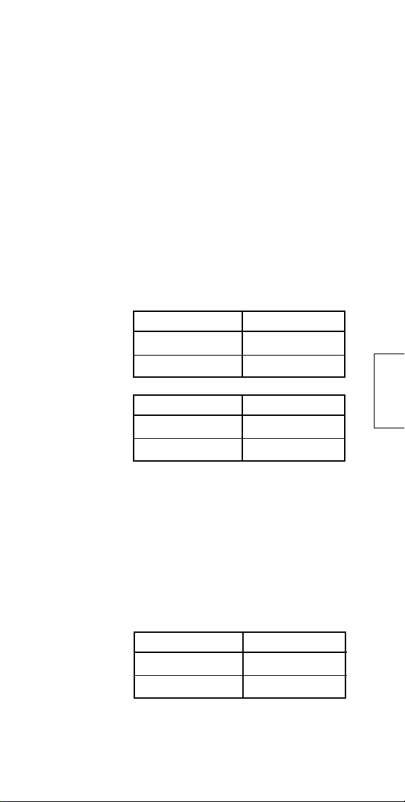
Step 3: Determine installation
mode
KB mode
RS232 mode Open All open All open
Model 1210/1220 reader supports
both keyboard wedge mode and
RS232 mode in one unit. The mode
has been set according to your
purchase order. In the event you
want to change it by yourselves,
please set the jumpers on the PCB
accordingly and refer to Chapter 2 for
keyboard wedge interface and
Chapter 3 for RS232 interface.
JP1 JP3 JP4
Short Pin 2&3 short Pin 2&3 short
10

2
Installing Model 1210/1220K
This chapter describes the procedure
for installing the 1210/1220K magnetic
stripe reader. Several keyboard
wedge parametersincluding keyboard type, message suffix, intercharacter delay, and track sentinels
may be adjusted by modifying the
dip-switch settings on the underside
of the magnetic stripe reader.
Step 1: Turn off your computer
If you have not already done so, turn
off your computer to avoid any
accidental damage to the card reader
and your computer.
Step 2: Set transmission mode and keyboard type
The first three dip-switches and SW7
on Model 1210/1220K allow for the
selection of the transmission mode
and keyboard type. Locate your
keyboard model and set the dipswitches accordingly. This card
reader offers 2 modes for data
transmission, you are recommend to
use the default SCAN MODE
setting for normal operation with full
PC/AT compatibility. For non-US
keyboard characters, please set the
11

Installing Model 1210/1220K
switch to ALT mode. And you are
advised to switch on the Num Lock
key under WINDOWS when you are
using the ALT mode.
MODE SW1 SW2 SW3 SW7
IBM PC-XT OFF OFF OFF OFF
IBM PC-AT ON OFF OFF OFF
IBM PS/55, PS/2 OFF ON OFF OFF
50/60/70/80
ALT
IBM PS/2 ON ON ON OFF
25/30
IBM PS/2 ON OFF ON OFF
3477
SCAN MODE * OFF ON ON ON
Step 3: Set message suffix
Switch 4 activates CR/LF (Carriage
Return and Line Feed) at the end of
data from the magnetic stripe. Set the
dip switches according to your
requirements.
12
CR/LF SW4
ENABLE * ON
DISABLE OFF
It is also possible to activate CR or LF
at the end of each card swipe rather
than at the end of each track.
JP6
Add CR/LF at the OPEN
end of each track *
Add CR/LF at the SHORT
end of card swipe

Installing Model 1210/1220K
Step 4: Set inter-Character delay
The inter-character delay is used to
adjust the speed to avoid the garbage
data transmission from the card reader
through the keyboard wedge. These
fine-tuning adjustments are helpful
when connecting to terminal, notebook computer or the one that is not
100% IBM-compatible.
INTER MESSAGE DELAY
0 msec * OFF OFF
10 msec ON OFF
20 msec OFF ON
50 m sec ON ON
SW5 SW6
Step 5: Set start and end sentinels
The start and end sentinels following
ANSI 4.16 and ISO 7811/2 may be
activated with switch 8.
SENTINEL SW8
ENABLE ON
DISABLE * OFF
13

Installing Model 1210/1220K
Step 6: Connect to computer
Unplug the PC keyboard cable from
the computer. Plug the keyboard
cable into the 5-pin female end of the
T-connector provided. Plug the male
end of the T-connector into the
keyboard port of your computer. An
installation diagram is shown below.
Step 7: Turn on computer
Turn on your computer. The computer should boot up normally.
Model 1210/1220K will beep to
indicate that it is ready for operation
Step 8: Turn to Chapter 4
You are now ready to test your 1210/
1220K magnetic stripe reader. Turn to
Chapter 4.
14

3
Installing Model 1210/1220R
This chapter describes the procedure
for installing the 1210/1220R magnetic
stripe reader. Several RS232 parametersincluding baud rate, data bits,
parity, message suffix, and track
sentinelsmay be adjusted by
modifying the dip-switch settings on
the underside of the magnetic stripe
reader.
Step 1: Turn off your computer
If you have not already done so, turn
off your computer to avoid any
accidental damage to the stripe reader
and computer.
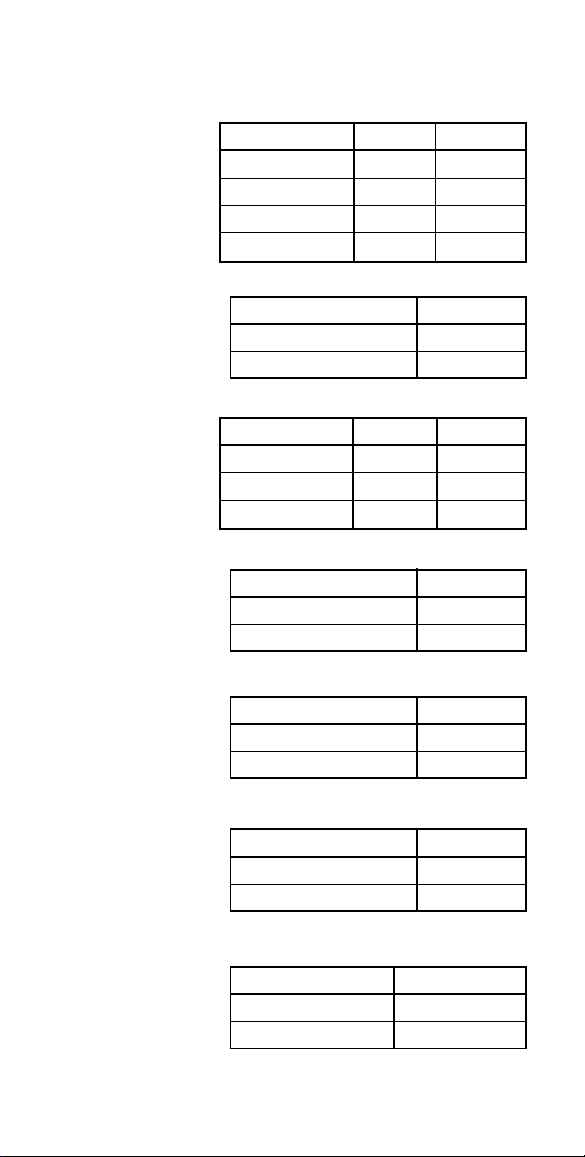
Step 2: Decide the ways of
communication
The 1210/1220R supports single or
dual RS232 communication. You can
set the jumpers on the PCB inside
housing according to the following
table by yourselves. We also offer
the optional RS232 Y-cable(GC-1210Y) for the dual RS232 communication.
Single RS232*
communication
Dual RS232
Single through
DB9 Female
Single through
DB9 Male
JP1 JP3 JP4
Open All open All open
Open Pin1&2 short Pin1&2 short
Open Pin1&2 short ALL open
Open ALL open Pin1&2 short
15

Installing Model 1210/1220R
Step 3: Set baud rate
The baud rate must be set to match
your system requirements. Select the
appropriate baud rate and set dipswitches 1 and 2 accordingly.
BAUD RATE SW1 SW2
19200 bps ON ON
9600 bps * OFF ON
2400 bps ON OFF
1200 bps OFF OFF
Step 4: Set data bits
Dip-switch 3 controls the data-bits
setting. Set the switch ON for 8 data
bits and OFF for 7 data bits.
Step 5: Set parity
PARITY SW4 SW5
16
DATA BITS SW3
8 BITS * ON
7 BITS OFF
Parity may be set to ODD, EVEN, or
NONE with switches 4 and 5 in
combination.
EVEN ON ON
ODD OFF ON
NONE * OFF OFF
Installing Model 1210/1220R
Step 6: Set message suffix
Switch 6 activates CR (carriage return)
at the end of each track of information
from the magnetic stripe. Likewise,
switch 7 activates LF (line feed) at the
end of each track. Set the dipswitches according to your requirements.
It is also possible to activate CR or LF
at the end of each card swipe rather
than at the end of each track. Contact
your distributor for more information.
CR SW6
ENABLE * ON
DISABLE OFF
LF SW7
ENABLE * ON
DISABLE OFF
Step 7: Set start and end sentinels
The start and end sentinels may be
activated with switch 8.
SENTINEL SW8
ENABLE ON
DISABLE * OFF
17

Installing Model 1210/1220R
Step 8: Decide on power access
The RS232 connection requires +12V
DC. This may be provided through
an internal connection in your
computer or through an external
connection to a 110V/220V adapter.
The components for an internal
connection are provided. If you are
using an external connection, be sure
that your adapter conforms with the
specifications listed in Appendix I;
then go to Step 9.
Step 9: Using internal power source
Please refer to the installation diagram
on the following page. Remove the
access cover to your computer.
Mount the +12V DC power plate on
an available expansion slot in the
back of your computer. Attach the 4pin male connector to the open female
connector of the same type in your
computer. Alternatively, an internal
power source my be available already
if the 9-pin RS232 port on your
computer or terminal matches the
1210/1220R pin assignment (see
Specifications in Appendix I).
18

Installing Model 1210/1220R
Step 10: Connect to your computer
Connect the 9-pin female RS232
connector (DB9F with DC jack) to the
male equivalent (DB9M) RS232 port
on your computer or terminal.
Provide power to the DC jack on the
DB9F connector using either a cable
connection to the +12V DC power
plate or an external adapter.
19

Installing Model 1210/1220R
Step 11: Turn on your computer
Turn your computer. It should boot
up normally. The card reader should
activate with a beep indicating a
successful installation. You are now
ready to test your 1210/1220R
magnetic stripe reader. Turn to
Chapter 4.
20

4
Testing and Troubleshooting
Testing 1210/1220K (keyboard interface)
Hold the 1210/1220K magnetic stripe
card reader or secure it on a flat
surface. Slide a magnetic stripe card
through the bi-directional card slot,
making sure that the magnetic stripe
is facing the magnetic head of the
card reader.
Model 1210/1220K will beep to
indicate a successful read. The card
data will display on the screen in the
format which was programmed into
the card reader.
Testing 1210/1220R (RS232 interface)
In order to test the RS232 interface,
the computer must be operating in a
terminal or on-line mode. This can be
done by using terminal-emulation
utility software such as TELIX and
PROCOMM. Alternatively, a simple
program written in BASIC is sufficient
for this purpose:
10 openCOM1:9600,N,8,1,rs,ds,cs as #1
20 input #1, A$
30 print A$
40 go to 20
With this program running, slide a
magnetic stripe card through the bidirectional card slot, making sure
21

Testing and Troubleshooting
that the magnetic stripe is facing the
magnetic head of the card reader.
Model 1210/1220R will beep to
indicate a successful read. The card
data will display on the screen in the
format which was programmed into
the card reader.
Troubleshooting Series 1210/1220
SolutionSituation
Card reader
does not
transmit the
correct data
On 1210/1220K keyboard wedge
version: Be sure that the dipswitch setting corresponds with
the type of keyboard. Try
adjusting the inter-character delay,
perhaps your computer keyboard
interface is not 100% IBM AT
compatible.
On 1210/1220R RS232 version:
check the RS232 parameter
settings (baud rate, parity, etc.).
Be sure that it matches the
requirements of your application
system.
22
Card reader
does not
transmit any
data
Check the magnetic stripe on the
card. Is it in good condition?
Adjust the speed with which you
swipe the card through the reader
so that it is not too fast nor too
slow.

A
Appendix I
Specifications
Decoding Capability
Card Reading Speed
Magnetic Head Life
Status Indicator
Parameter Settings
System Compatibilities
One Track: Track 1 or Track 2
or Track 3
Two Tracks: Tracks 1 & 2 or
Tracks 2 & 3
Three Tracks: Tracks 1 & 2 &
3
8 to 125 cm/sec
Bi-directional
300,000 passes
Audible beep and RED LED
for each successful reading
Green LED for standby status
Start and end sentinel
Inter-character delay
Message suffix
RS232 parameters (baud rate,
data bit, parity)
Model 1210/1220K keyboard
wedge interface operates with
IBM XT, AT, PS/2 and
compatibles.
Model 1210/1220R has
standard RS232 DB9F interface
for easy installation within any
existing system that has RS232
port capability.
23

Specifications
Physical
Environmental
Power Requirements
Power Consumption
Interface Connector
Pin Assignments
Dimensions: 100mm x 42mm x
27mm (LxWxH)
Weight: 100g
Operating temperature: 0-40 °C
Storage temperature: -20-60 °C
Humidity: 10% - 90% RH ( non-
condensing)
Model 1210/1220K: +5V from
host or terminal
Model 1210/1220R: +12V DC
directly from host, or through
adapter from external 110V/220V,
50Hz/60Hz source with polarity as
follows:
During operation: max 300 mA
While idle: 60 mA
DB9F RS232 Interface
#2: TX
#3: RX
#5: Ground
#9: +12V DC Power
24
DIN5 Keyboard Interface
#1: PC Clock
#2: PC Data
#4: Ground
#5: +5V
DIN5 Keyboard Interface
#1: PC Clock
#2: PC Data
#4: Ground
#5: +5V

A
Appendix II
The Installation for ACDE Version
This ACDE version of 1210 card
reader is designed for some special
application, it is performed to convert
: ; < = > data of the track II & III
into ABCDE characters following
are its switch and jumper setting.
Keyboard mode
ON OFF
SW1 NON-US KEYB US KEYB *
SW2 RESERVED *
SW3 SEND LRC NO LRC *
SW4 ENABLE * DISABLE
CARRIAGE RETURN CARRIAGE RETURN
DELAY SW5 SW6
0 msec* OFF OFF
10 msec ON OFF
20 msec OFF ON
50 msec ON ON
ENVIRONMENT SW7
DOS * OFF
WINDOWS ON
SENTINEL SW8
ENABLE ON
DISABLE * OFF
JP6: Set inter character delay default
setting is OFF.
25
The Installation for ACDE Version
RS232 mode
BAUD RATE SW1 SW2
19200 bps ON ON
9600 bps * OFF ON
2400 bps ON OFF
1200 bps OFF OFF
DATA BITS SW3
8 BITS * ON
7 BITS OFF
PARITY SW4 SW5
EVEN ON ON
ODD OFF ON
NONE * OFF OFF
CR SW6
ENABLE * ON
DISABLE OFF
26
NOTE:
LF SW7
ENABLE * ON
DISABLE OFF
SENTINEL SW8
ENABLE ON
DISABLE * OFF
LRC JP6
ENABLE ON
DISABLE * OFF
JP6 is located on the PCB.

27


Copyright © 2000
Jarltech International Inc.
Print in Taiwan
ISSUED: July,2000' - V 4

 Loading...