


1
OPERA TION
MANUAL
ISO 9002 Certified
Lead with technology
Win customers with service
Programmable Keyboard
MODEL 8081

2

3
© Jarltech International Inc. 1997. All rights reserved.
Under the copyright laws, this manual may not be copied, in
whole or in part, without the written consent of Jarltech.
Every effort has been made to ensure that the information in
this manual is accurate. Jarltech is not responsible for
printing or clerical errors.
Jarltech International Inc.
3F, No. 1, Lane 538, Chung Cheng Road, Hsin Tien, Taipei,
Taiwan, R.O.C.

4

5
This equipment has been tested and found to comply with
the limits for Class A digital device. Pursuant to Part 15 of
the FCC Rules. These limits are designed to provide
reasonable protection against harmful interference in a
residential installation. This equipment generates, uses, and
if not installed and used in accordance with the instructions
may cause harmful interference will not occur in a particular
installation. If this equipment does cause harmful interference to radio or television reception, which can be determined by turning the equipment off and on. The user is
encouraged to try correct interference by one or more of the
following measures:
- Reorient or relocate the receiving antenna.
- Increase the separation between the equipment and
receiver.
- Connect the equipment into an outlet on a circuit different
from that to which the receiver is connected.
- Consult the dealer or an experienced radio/TV technician for
help. This booklet is available from the U.S. government
Printing Office, Washington, DC 20402, Stock NO.004000-00345-4.
CAUTION:
Any changes of modifications not expressly
approved by the grantee of this device could void the
users authority to operate the equipment.
Operation is subject to the following two conditions:
(1) This device may not cause harmful interference.
(2) This device must accept any interference received including
interference that may cause undesired operation.

6

7
1. Before You Install .............................................2
2. Preparation for Programming ........................4
3. How to Program Keyboard ............................. 7
4. Operating Your Keyboard................................16
5. Testing .............................................................18
Appendix I: Keyboard Maps ................................ 19
Appendix II: Hex Conversion Table ....................21
Appendix III: Specifications ................................. 22
Contents

8
1
Before You Install
The Jarltech 8081 programmable keyboards have been
specially designed for use with personal computers or
terminals in Point-Of-Sale and industrial applications. This
manual describes how to connect the Jarltech keyboard to
your system, how to design a keyboard layout which meets
your special requirements, and how to install your programmed keyboard layout into the Jarltech keyboard.
Model 8081 is a tactile keyboard with eight rows and ten
columns for a maximum of 80 keys. Single, double, and
quadruple key caps may be used. The keyboard layout and
key functions are completely programmable.
The keyboard has both RS232 and IBM keyboard wedge
interface capabilities.
Step 2: Review packing list
Please ensure that your keyboard shipment is complete.
Jarltech tactile keyboard 8081includes:
1 pce 8081tactile keyboard with keyboard wedge cable
1 pce Operation Manual
1 pce RS232 cable with DC jack connector
1 pce +12V DC Power Plate with internal power cable
1 pce DC cable
2 pce keylock
1 pkg key caps
Step 1: Turn off your computer
By shutting off your computer, you will prevent any accidental damage to the keyboard and your computer.

9
Before You Install
General Description of Keyboards
Model 8081
A: Tactile Keyswitch
B: Single Keycap
C: Double Keycap
D: Quad Keycap
E: Optional Magnetic Card Reader
Jarltech Membrane keyboard 8081MU includes:
1 pce 8081membrane keyboard with keyboard wedge cable
1 pce Operation Manual
1 pce RS232 cable with DC jack connector
1 pce +12V DC Power Plate with internal power cable
1 pce DC cable
2 pce keylock

10
2
Preparation For Programming
Step 1: Turn off your computer
This chapter describes connection of Jarltech Model 8081
keyboards to a host computer for programming. The keyboard
is programmed through the RS232 port, regardless of whether
the ultimate interface during operation will be RS232 or
keyboard wedge.
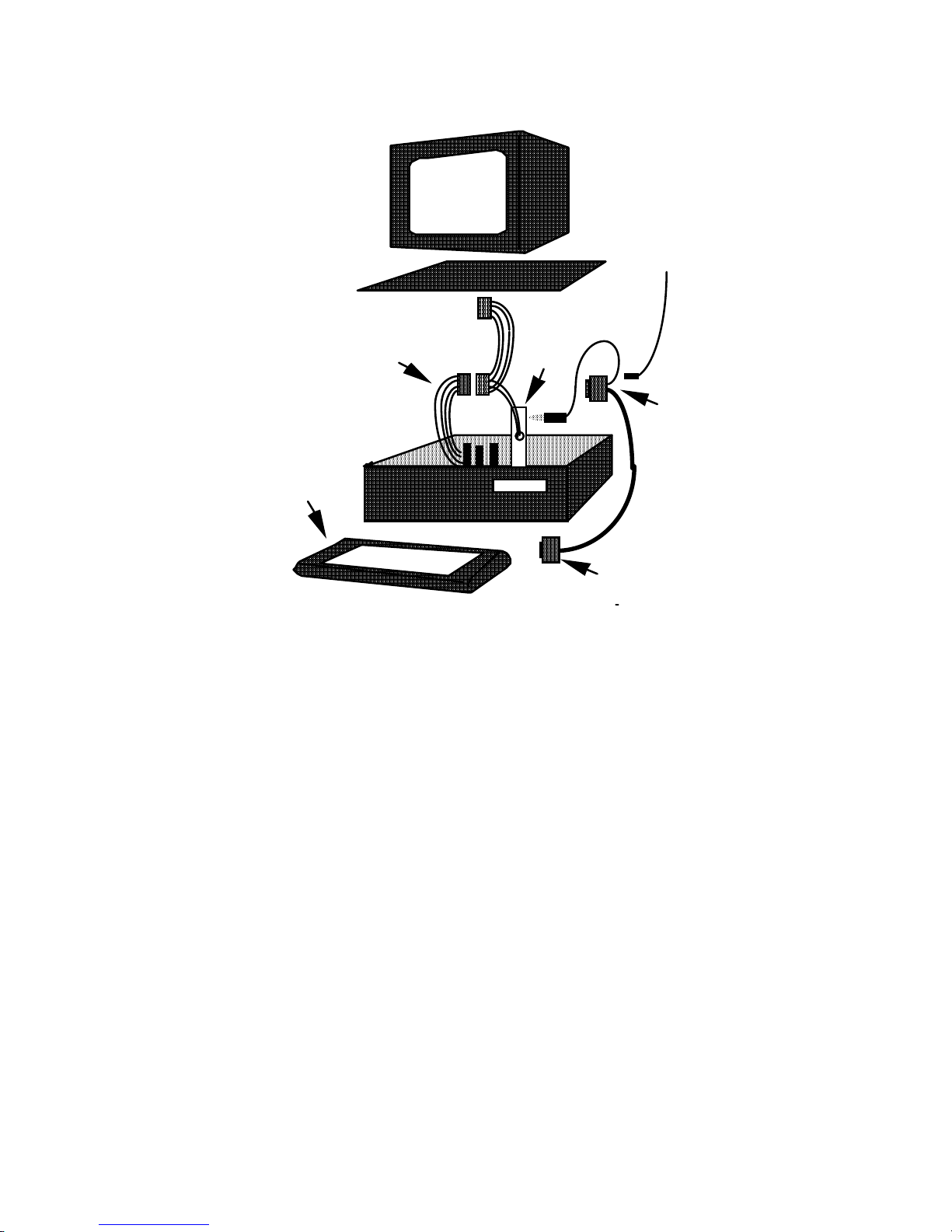
Disconnect the power to your computer by unplugging it from
the power source. Remove the access cover to your computer. Mount the +12V DC power plate on an available
expansion slot in the back of your computer. Attach the 4-pin
male connector to the open female connector of the same type
of the switching power in your computer.
Review the installation diagram. Replace the computer's
access cover and power cord once the internal connections
are made.
If you have not already done so, turn off your computer to
avoid any accidental damage to the keyboard and your
computer.
Step 3: Using internal power source
Step 2: Decide on power access
The keyboard requires +12V DC for programming via the
RS232 port. This may be provided through an internal
connection in your computer or through an external connection to a 110V/220V adapter. The components for an internal
connection are provided. If you are using an external adapter,
be sure that it conforms with the specifications listed in
Appendix III and then go to Step 4.
11
Step 4: Connect keyboard to computer
Attach the 9-pin female (DB9F) RS232 connector with built-in
DC jack to an available male equivalent (DB9M) RS232
communication port on your computer. Provide power to the
DC jack on the DB9F connector using either a cable connection to the +12V DC power plate or an external adapter.
Connect the 8 din male side of the RS232 cable to the rear face
of the keyboard. This 8 din port serves either keyboard wedge
or RS232 interface depends on the pin assignment. A description of each pin can be found in Appendix III.
External
+12V DC
Power Supply
(Optional)
Internal +12V DC
Power Supply
RS232
(DB9F)
with DC Jac
to COM port
Power
Plate
to PC
Slot
8001 and 8002 Keyboard
Preparation for Programming
RS232
(DB9M)
to Port #1 on
Keyboard
8001 or 8002
Keyboard
Preparation for Programming
Jarltech

12
Preparation for Programming
Step 5: Turn on your computer
Once all connections are complete, turn on your computer. It
should boot up normally. The keyboard will "beep" three
times.
The keyboard is now ready for programming. Turn to Chapter
3.

13
3
Step 1: Correct the switch
1. Set SW-1 according to the configurations you desired.
2. Set SW- 2,3 and 4 to default setting ON.
1. You will hear 3 beep sounds.
2. If the LOCK on 8001 is at OFF,then both the green & red
LEDs will light on and the 8081 cant work now. Please just
turn the LOCK ON.
3. If the LOCK is ON, the green LED light is on & the red LED
is off. Now,the 8081 is under normal working mode.
The red LED will light on during the porgramming mode and
light off when programming has been completed.
How to Program Keyboard
Programming
Step 2: Power ON the 8081
S W O N OFF DEFAULT
1
IBM Keyboard Mode RS232 Keyboard Mode
ON
2 Factory Setting ON
3 Factory Setting ON
4
Disable MAG.Card Reader Enable
MAG.Card Reader
ON
5
Programming Mode Normal Mode
OFF

14
NOTE:
When running the POS.EXE this program will detect the PC
configuration and allow you to select com 1 or com2 if they
are present.
The POS.EXE software will create an OPTIONS.STP file to
store your setup, automaticly and create an database files
(with ADB extension) to reserve your own keyboard map
setups as well.
After the POS.exe is executed,the first menu presented to the
user is
Demonstration
Terminal Mode.
Programming.
Info Screen.
Exit Pos.
Select Programming
Programming:
This option is for programming of Jarltech POS family.
Options on selecting are moving cursor UP or DOWN or
press the letter which is highlighted then Press <ENTER> to
select.
Press the <ESC> key to select previous menu.

15
Programming Procedures
From the main menu, after the programming function is
selected , this screen will display on your screen :
Select Program Port.
Setup 8001 / 2 and 8081/2 Programming com port = COM1
Setup 8005 / 2.
Setup 8006.
1. Select Select Program Port.
This function allows you to select the Programming com
port of your PC. By pressing <Enter> will tag between
Com1 and Com2.
All programming is defaulted to 9600 bps. If the 8081 has a
different operation baud rate, then the operation baud rate
will be implemented after exiting programming mode.
2. Select Setup 8001/2 and 8081/2
This function allows you to program all the JARLTECH
KEYBOARDs.
The programming features include program keyboard
setting, setup keyboard parameters first, retrieve map from
data base, create new data base and delete map from
database. Please refer to Section 2 for details.
NOTE:
Section 1 Programming

16
Section 2 Setup 8081 Keyboard
From the programming menu, after Setup 8001/8002 and 8081/
2 is selected, the screen will display:
Program keyboard settings.
Setup keyboard parameters first.
Retrieve map from data base.
Create new data base.
Delete map from database.
Step 1: Select Create new data base.
This option asks you for a name to which it will create
a new database on your PC, to which you can store
your own keyboard maps.
Database name upto 8 chars without ext:
JARLTECH
There are 8081 & 8082 two maps contained in the
DEFAULT.ADB. You also can select Retrieve map from
data base to load up 8081 for IBM keyboard wedge
mode or 8082 for RS232 mode from DEFAULT.ADB.
Step 2: Select Setup keyboard parameters first.
Define a key - 8001.
Define a key - 8002.
Define a key - 8081/2
Setup Misc timings.
Read keyboard map.
Name keyboard map.
Save to data base file.
(1) Define a key - 8081/2
This function provide a key map. For every key a
Hex value can be assigned. The user can use the
cursor key to move and change the value. Just
move the cursor to the key which you want to
program and press F6 then enter new value. Also
Shift, CTRL, ALT, Click, Runout can be assigned
with each key by F5.
NOTE:

17
NOTE:
If using keyboard for RS232 mode, the Shift, CTRL and
ALT are not implemented.
If you want to use RS232 mode,the key value is from Hex 00
to FF.
If you want to use IBM keyboard wedge mode, the key
value is coorespondent to the key table refer to Appendix I.
If using POS demo on OS2, you will have to press ALT
and HOME. This will display the key layout. Also you
will have to press ALT and P which assigns the
keyboard to the window.
When you like to escape from this window,press ALT and
HOME.
(2) Setup Misc timings.
Set Delay before run out. ? * 10mS.
Set Rate for run out. ? * 10mS.
Set Beep time. ? * 10mS.
Set Click time. ? * 10mS.
Set Keyboard Data stream ID BYTE!!
Set Aux RS232 Data stream ID BYTE!!
Set Baud rate. 300 - 19200 BPS.
(a) Set Delay before run out. ? * 10mS.
Run out delay is the time taken from the key
depression until the key starts to run out.
Enter DELAY BEFORE KEY RUN, Entry is a decimal
multiple of 10mS:6
A good value to enter here is 6 .
(b) Set Rate for run out. ? * 10 mS.
Rate for run out is the rate between two repeat
keys.
Enter KEY RUN REPEAT RATE, Entry is a decimal
multiple of 10mS:-
10
A good value to enter here is 10.

18
(c) Set Beep time. ? * 10mS.
Beep time is the duration for the long beep tone
(error tone)
Enter ERROR BEEP TIME, Entry is a decimal
multiple of 10mS:100
A good value to enter here is 100.
(d) Set Click time. ? * 10mS.
Click time is the duration for the short beep tone
(valid key press tone)
Enter KEY CLICK TIME, Entry is a decimal
multiple of 10mS:-×
5
A good value to enter here is 5.
(e) Set Keyboard Data stream ID BYTE!!
Keyboard data stream ID byte is a Hex value
prefixed to all data coming from the keypad
Enter decimal ID value for the keyboard data stream
0
The keyboard has a Redirection Pointer. Each time
the Redirection Pointer changes from the RS232
port to the keypad, you can order the 8081 to send
this ID VALUE. This ID is only sent once before
the key value is sent, So the host device will know
the data has come from the keypad on the keyboard.
(f) Set Aux RS232 Data stream ID BYTE!!
Enter decimal ID VALUE for the AUXILIARY RS232
data streams:0

19
The keyboard has a Redirection Pointer.
Each time the Redirection Pointer changes from the
keypad to the RS232 ports, you can order the 8081
to send this ID VALUE. It is only sent once before
the incoming com port is transmitted on. So HOST
will know the data is coming from the RS232 ports
on the keyboard.
(g) Set Baud rate. 300 - 19200 BPS.
Enter keyboards baud rate -300,600,1200,2400,
4800,9600,19200
If using 8081 in keyboard wedge mode and a mag. stripe
reader or CCD barcode scanner or other RS232 input
devices is present. The baud rate should be set at 1200
bps,and the peripherals have to be set at 1200 bps as well.
(3) Read keyboard map.
This function allows you to read (copy) keyboard
map from a keyboard and to store it in a data base
file. From which then can be changed and reloaded
back to the other keyboards.
Working ... Please Wait!
WAITING RESPONSE, FLICK PROGRAM SWITCH ON KEYBOARD!
(4) Name keyboard map.
This function asks you for a name of up to 20
characters. This is used to save the keyboard map
under an individual name.
Keyboard map name up to 20 characters:-
LINEAR
NOTE:

20
(5) Save to data base file.
This function saves the named keyboard map to a
data base file.
GET DATABASE
JARLTECH.ADB
Select data base. If a keyboard map exists with the
same name, then the user will be prompted.
Database entry already exists! Replace existing entry ...
(Y/N): ?
(6) Delete map from database.
This option will provide a list of databases to be
selected from.
GET DATABASE
JARLTECH.ADB
Once selected, a list of keyboard maps will be
presented
DATA-JARLTECH.ADB
style-1
ARE YOU SURE ON DELETE ... (Y/N): ?
Step 3. Retrieve map from data base.
This option will provide a list of databases to be
selected from and each database will present a list of
keyboard maps within that database to be selected
from.
GET DATABASE
JARLTECH.ADB

21
Step 4. Program keyboard settings.
This function is used to download the keyboard map
into 8081 keyboard. Before selecting this function,
please refer to retrieve map from data base. and
setup keyboard parameters first.
8002 KEYBOARD
8001 KEYBOARD
8081/2 KEYBOARD
To select 8081/2 Keyboard mode then following
message will be shown on:
Please follow the next instructions carefully!!
STEP 1: Set DIP switch 5down
STEP 2: Set DIP SWITCH 5up
NOTE : If there is no response then,
CHECK: Cable & Comm port are set correctly
CHECK: That the keyboard has powered up
CHECK: DIP Switch 5 is up before attemping
programming
NOTE: if DIP Switch 5 was Down then the keyboard
will not respond!
NOTE: If you are unsure please refer to users maunal
supplied.
PRESS [ESC] -to exit programming mode at any time

22
4
The Jarltech 8081 keyboards may be operated in conjunction
with your host computer or terminal using either a keyboard
wedge interface or an RS232 interface. As your requirements
change in the future, the keyboards may be re-programmed to
match the interface you require.
Step 1: Connect keyboard to computer
If your chosen operating mode utilizes the RS232 interface and
you currently have a connection between Port #1 on you
keyboard and a communication port on your computer (as you
did during the programming process), the keyboard is ready
for operation.
If your chosen operating mode uses the keyboard wedge,
disconnect the RS232 cable from 8 din port and connect the
keyboard cable attached on 8081 to computer. Then install
your keyboard to 8 din port on Jarltech 8081 keyboard. (see
Diagram 4.1)
Operating Your Keyboard

23
Operating Your Keyboard
An internal RS232 interface is configured on the Jarltech 8081
circuit board for connection with a magnetic stripe reader.
This may be attached to the keyboard if requested at the time
of purchase. To use this attached card reader, configure the
dip-switch accordingly:
Switch Position Reason
#4 OFF Magnetic Stripe Reader enabled
Your keyboard are now configured for use with your application software.

24
5
Testing
Testing the RS232 mode of operation
Using the POS.EXE software provided, select TERMINAL
MODE from the Main Menu (see Diagram 5.1).
Press any key on the Jarltech keyboard. The programmed
value of that key will appear on the screen. Press [ESC] to exit
TERMINAL MODE.
Under the system prompt:, type COPY CON
C:\>COPY CON [ENTER]
Press any key on the Jarltech keyboard. The programmed
value of that key will appear on the screen. Return to the
system by entering [CTRL+C].
Testing the keyboard wedge mode of operation

25
A
Appendix I: Keyboard Maps
Map #1: Double/Quad Key - 80 Key Actuator for keyboard wedge mode
This map is named
8081
in DEFAULT.ADB
2 a
31
23
36
29
48
42
00
39
32
38
22
45
41
47
44
37
3b
1e
35
46
4a
43
49
2c
3a
01
04
0a
0a
0c
40
1f
25
01
04
0b
0b
0c
40
2d
26
02
05
14
11
0e
17
2e
1d
02
05
15
12
0f
3d
2f
20
03
06
16
13
10
33
24
26
03
06
08
09
3f
3f
30
21
07
07
08
09
3f
3f
MAP #1: Double/Quad Key - 80 Key Actuator
for Keyboard Wedge Mode SW1=ON

26
Keyboard Maps
Map #2: Single Key for RS232 mode
This map is named 8082 in DEFAULT.ADB
00
0a
14
1e
28
32
3c
46
01
0b
1s
1f
29
33
3b
47
02
0c
1b
20
2a
34
3e
48
03
0d
17
21
26
35
3f
49
04
0e
18
22
2c
36
40
4a
05
0f
19
23
2d
37
41
4b
06
10
1a
24
2e
38
42
4c
07
11
1b
25
2f
39
43
4d
08
12
1c
26
30
3a
44
4e
09
13
1b
27
31
3b
45
4f
MAP #2: Single Key for RS232 mode
SW1=OFF
27
A
Appendix II: Hex Conversion Table
The Hex Conversion Table lists the Hex values which Jarltech
has assigned to each IBM keyboard character. This table is
designed for programming the Jarltech keyboard to be used in
the keyboard wedge mode of operation.
Key
Hex Value
Key
Hex Value Hex Value
34
35
36
37
38
39
3A
3B
3C
3D
3E
3F
40
41
42
43
44
45
46
47
48
49
4A
Z
X
C
V
B
N
M
,
.
/
ENTER
SPACE
UP ARROW
LEFT
ARROW
RIGHT
ARROW
DOWN
ARROW
INSERT
DEL
HOME
END
PAGE UP
PAGE DN
ESC
F1
F2
F3
F4
F5
F6
F7
F8
F9
F10
F11
F12
`
1
2
3
4
5
6
7
8
9
0
=
00
01
02
03
04
05
06
07
08
09
0A
0B
0C
0D
0E
0F
10
11
12
13
14
15
16
17
18
19
1A
1B
1C
1D
1E
1F
20
21
22
23
24
25
26
27
28
29
2A
2B
2C
2D
2E
2F
30
31
32
33
\
BS
TAB
Q
W
E
R
T
Y
U
I
O
P
[
]
CAPS
A
S
D
F
G
H
J
K
L
;
Key

28
A
Appendix llI: Specifications
Tactile keyboard
8 rows x 10 columns
Cherry keyswitch
ABS plastic key caps
Single, dual and quadruple key caps available
User-definable key layout
RS232 interface: +12V DC from host computer or through
adaptor from external 110/220V AC source with polarity as:
Keyboard interface: +5V DC from host computer
Dimension: 305mm (L) x 175mm (W) x 22mm (H)
Weight: 750g
Model 8081 Keyboard
Dip-Switch Settings
Power Requirements
Switch ON OFF
#1 Keyboard Wedge Map * RS232 Mode
#2 Not in Use * Software Map
#3 Not in Use * Cpu Map #2
#4 Disable Mag Card Reader * Enable Mag Card
Reader
#5 Programming Switch Normal Operation
* Marks default setting.
Physical

29
Specifications
Internal RS232 Interface (for magnetic stripe reader)
#1: GROUND
#2: TX
#3: RX
#4: +5V DC Power
#1: CLOCK #5: +5V DC
#2: DATA #6: RX
#3: NC #7: +12V DC
#4: GND #8: TX
#1: PC CLOCK
#2: PC DATA
#3: NC
#4: GND
#5: +5V DC
Keyboard Port
One internal RS232 interface for optional magnetic stripe
reader
1 external 8 din port which serves either external IBM
keyboard or RS232 interface
1 Keyboard Port cable serves keyboard wedge interface.
Communication Ports

30

31

32
Copyright@2000
Jarltech International Inc.
Printed in Taiwan
ISSUED: jULY.,2000-V3.01

33
 Loading...