


1
Programmable Keyboard
SERIES 8010
OPERATION
MANUAL
ISO 9002 Certified
Lead with technology
Win customers with service

2

3
© Jarltech International Inc. 1997. All rights reserved.
Under the copyright laws, this manual may not be copied,
in whole or in part, without the written consent of Jarltech.
Every effort has been made to ensure that the information
in this manual is accurate. Jarltech is not responsible for
printing or clerical errors.
Jarltech International Inc.
3F, No. 1, Lane 538, Chung Cheng Road, Hsin Tien, Taipei,
Taiwan, R.O.C.

4

5
This equipment has been tested and found to comply with the
limits for Class A digital device. Pursuant to Part 15 of the FCC
Rules. These limits are designed to provide reasonable protection
against harmful interference in a residential installation. This
equipment generates, uses, and if not installed and used in
accordance with the instructions may cause harmful interference
will not occur in a particular installation. If this equipment does
cause harmful interference to radio or television reception, which
can be determined by turning the equipment off and on. The user
is encouraged to try correct interference by one or more of the
following measures:
- Reorient or relocate the receiving antenna.
- Increase the separation between the equipment and receiver.
- Connect the equipment into an outlet on a circuit different from
that to which the receiver is connected.
- Consult the dealer or an experienced radio/TV technician for
help. This booklet is available from the U.S. government
Printing Office, Washington, DC 20402, Stock NO.004-00000345-4.
CAUTION:
Any changes of modifications not expressly
approved by the grantee of this device could void the
users authority to operate the equipment.
Operation is subject to the following two conditions:
(1) This device may not cause harmful interference.
(2) This device must accept any interference received including
interference that may cause undesired operation.

6

7
Contents
1. Before You Install
2. Preparation for Programming
4. Operating Your Keyboard
3. Programming Your Keyboard
5. Troubleshooting
Appendix I: Specifications
Appendix II: 8010M Template Guide
Appendix III : Quick Programming
Appendix IV : Translate the map of 8001or 8002 to 8010
Appendix V : Frequently Asked Questions
Appendix VI : Application Under Windows

8

9
1
Before You Install
The Jarltech 8010 programmable keyboards have been
specially designed for use with personal computers or
terminals in point-of-sale and industrial applications. This
manual describes how to connect the Jarltech keyboard to
your system, how to design a keyboard layout which meets
your special requirements, and how to install your keyboard
layout into the Jarltech keyboard.
Model 8010T is a tactile keyboard with seven rows and
fifteen columns for a maximum of 105 keys. Single, double,
and quadruple key caps may be used. Model 8010M is a
membrane keyboard configured with eight rows and fifteen
columns for a total of 120 keys. For both models, the keyboard layout, key functions and key data are completely
programmable.
Each keyboard has both RS232 and IBM keyboard wedge
interface capabilities. The 8010 keyboard is capable of
receiving data from any external RS232 device (e.g., bar code
scanner) and transmitting that data to a host computer via
either the keyboard wedge or an RS232 interface. A magnetic
stripe reading decoder is built into the circuit board of the
8010, allowing easy attachment of a card reader.
Step 1: Turn off your computer
By shutting off your computer, you will prevent any accidental damage to the keyboard and your computer.

10
Step 2: Review packing list
Before You Install
Please ensure that your keyboard shipment is complete.
Jarltech keyboard Model 8010T includes:
1 pce 8010T tactile keyboard
1 pce Operation Manual
1 pce keyboard wedge cable
1 pce RS232 cable with DC jack connector
1 pce +12V DC Power Plate with internal power cable
1 pce DC cable
1 pkg key caps
1pce Adapter (HC-80127)
Jarltech keyboard Model 8010M includes:
1 pce 8010M membrane keyboard
1 pce Operation Manual
1 pce keyboard wedge cable
1 pce RS232 cable with DC jack connector
1 pce +12V DC Power Plate with internal power cable
1 pce DC cable
1 pce membrane keyboard layout template
1pce Adapter (HC-80127)

11
Programming via the RS232 Port
2
Step 1: Turn off your computer
Step 2: Decide on power access
The keyboard requires +12V DC for programming via the
RS232 port. This may be provided through an internal
connection in your computer or through an external connection to a 110V/220V adapter. The components for an internal
connection are provided. If you are using an external adapter,
be sure that it conforms with the specifications listed in
Appendix I and then go to Step 4.
Step 3: Using internal power source
Review the RS232 installation shown in Diagram 2.1. Disconnect the power to your computer by unplugging it from the
power source. Remove the access cover to your computer.
Mount the +12V DC power plate on an available expansion
slot in the back of your computer. Attach the 4-pin male
connector to the open female connector of the same type in
your computer. Replace the computer's access cover and
power cord once the internal connections are made.
This chapter describes the connection of Jarltech Series 8010
keyboards to a host computer for programming. The Jarltech
keyboard may be programmed through either the RS232 port
or IBM keyboard port. If you are programming via the
keyboard port, turn to page 7.
If you have not already done so, turn off your computer to
avoid any accidental damage to the keyboard and your
computer.
Preparation For Programming

12
Preparation for Programming
Step 4: Connect keyboard to computer
Step 5: Disconnect peripherals from keyboard
Attach the 9-pin female (DB9F) RS232 connector with built-in
DC jack to an available male equivalent (DB9M) RS232
communication port on your computer. Provide power to the
DC jack on the DB9F connector using either a cable connection to the +12V DC power plate or an external adapter.
Connect the 9-pin male (DB9M) side of the RS232 cable to the
HOST port on the rear face of the keyboard.
While using the HOST port for programming the keyboard, be
sure that no peripheral devices are connected to any of the
remaining ports.

13
Preparation for Programming
Step 6: Confirm RS232 pin assignments
Step 7: Turn on your computer
Please ensure that the RS232 pin assignments on your
computer confirm with the pin assignments of the HOST port
on the Jarltech keyboard:
Pin #1: +5V Pin #7: RTS
Pin #2: RX Pin #8: CTS
Pin #3: TX Pin #9: +12V
Pin #5: GND
The pin assignments of all keyboard ports are found in the
specifications listed in Appendix I.
Once all connections are complete, turn on your computer. It
should boot up normally. The keyboard will "beep" three
times.
The keyboard is now ready for programming. Turn to
Chapter 3.
If you havent done so already, turn off your computer to
avoid any accidental damage to the keyboard. Refer to the
keyboard installation shown in Diagram 2.2.
Unplug the 101/102 keyboard cable from your computer. Plug
the 101/102 keyboard cable into female side of the T-connector on the Jarltech keyboard cable. Plug the male end of the
T-connector into the keyboard port of your computer.
Be sure that no peripheral device are connected to the
AUX1RS232 port on the Jarltech keyboard. Once all connections are complete, turn on your computer. It should boot up
normally. The keyboard will "beep" three times.
The keyboard is now ready for programming. Turn to
Chapter 3.
Programming via the Keyboard Port

14
Preparation for Programming

15
3
Programming Your Keyboard
The Jarltech keyboard may be custom programmed to meet
the requirements of your application software. This chapter
describes the procedure for programming a custom map into
the Jarltech keyboard.
This keyboard is available to emulate multi-national language
characters on your system. The *.TPL files enclosed in the
8010 programming software(8010.exe) are for this purpose.
Hereunder are the languages that the xx.TPL files stand for:
BE .TPL stands for Belgium
BR .TPL Brazil
CF .TPL Canadian-French
CZ .TPL Czechoslovakia (Czech)
SL .TPL Czechoslovakia (Slovak)
DK .TPL Denmark
SU .TPL Finland
FR .TPL France
GR .TPL Germany
HU .TPL Hungary
IT .TPL Italy
LA .TPL Latin America
NL .TPL Netherlands
NO .TPL Norway
PL .TPL Poland
PO .TPL Portugal
SP .TPL Spain
SV .TPL Sweden
SF .TPL Switxerland (French)
SG .TPL Switzerland (German)
UK .TPL United Kingdom
*US .TPL United States [Default]
YU .TPL Yugoslavia
Insert the diskette provided into the floppy disk driver of
your computer and copy all files onto your hard disk drive.
Enter the Jarltech 8010.EXE software under the system
prompt: C:\>8010 ; for US
or C:\>8010 /T:US ; for US
or C:\>8010 /T:GR ; for Germany
By pressing [ENTER], the 8010 main menu will appear on
Step 1: Load Jarltech 8010 software

16
Custom Programming
The programming software uses the following keystroke
short-cuts:
[F2] = Save work at any stage
[ALT+O] = OK (accept entries)
[ALT+C] = Cancel (entries)
[
¯¯
¯¯
¯
],
[[
[[
[
¬¬
¬¬
¬
], [
®®
®®
®
], [
--
--
-
] = Scrolling keys
[TAB] = Skip to next entry
[ESC] = Exit window
[ENTER] =
Accept selection, or switch
between enable and disable
If you have a color monitor, you will notice that some letters and numbers
on the screen are bright red. You may scroll directly to those dialog options
by pressing [ALT] plus the bright red letter or number.
NOTE:
your screen (see Diagram 3.1). The screen has three menus:
FILE: contains routines for creating, opening, closing and
saving files, and for quitting the 8010 program.
OPTIONS: contains routines for setting operating mode,
RS232 parameters, keyboard wedge parameters, auxiliary
device parameters, card reader parameters, Jarltech
keyboard parameters, and keyboard layouts.
PROGRAMMING: contains routines for programming
your defined keyboard layout into the memory of the
Jarltech keyboard.

17
Custom Programming
Step 2: Create or open a keyboard map file
Under the FILE menu, select NEW and press [ENTER] if you
wish to begin a new map file (see Diagram 3.2) or select OPEN
to modify an existing map file (see Diagram 3.3). In either
window, the extension .MAP is automatically appended to
whatever filename you choose. The <¯> lookup button in the
OPEN window to provides access to all previously saved
map files within your current directory.
Once you have entered a new or existing filename, press
[ALT+O] to accept your entry. The name of an existing file
will immediately appear on the right-hand side of the menu
bar; the name of a new file will appear as soon as you leave
the FILE menu.

18
Custom Programming
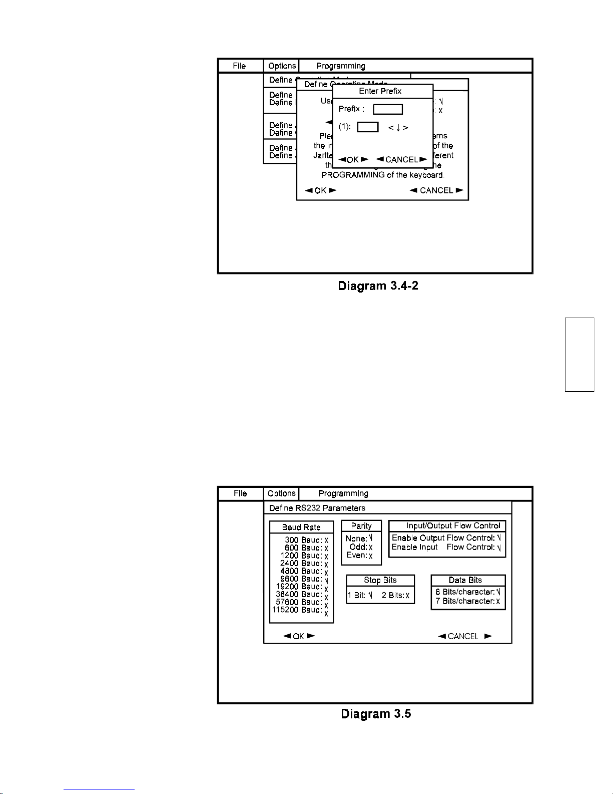
Step 3: Define Operating Mode
Scroll [® ] to the OPTIONS menu, select DEFINE OPERATING MODE and press [ENTER]. As shown in Diagram 3.4-1,
you may choose between KEYBOARD WEDGE INTERFACE
and RS232 INTERFACE. Scroll to your choice and press
[ENTER].
This selection concerns the actual connection between
Jarltech keyboard and host and may be different than the
configuration during your keyboard programming.
Scroll to OK or press [ALT+O] to accept your choice.
Global Auxilly Prefix append one character to the data no
matter this data comes from magnetic card reader or AUX1.
see Diagram 3.4-2
NOTE:
19
Custom Programming
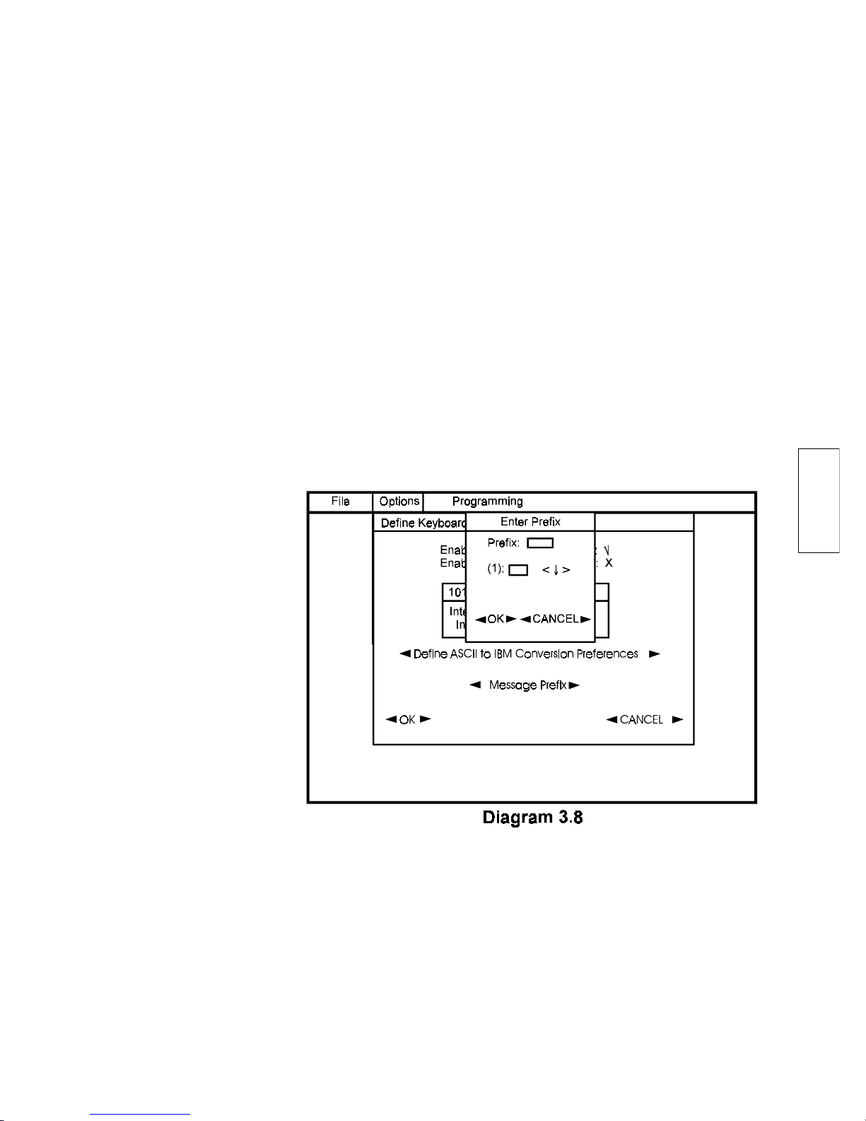
Setting the RS232 parameters is required for the proper
functioning of both the host and the auxiliary RS232 ports.
Scroll [¯] to DEFINE RS232 PARAMETERS and press
[ENTER]. A window similar to Diagram 3.5 will appear.
Step 4: Define RS232 Parameters

20
There are selection boxes for baud rate, parity, stop bits, data
bits and input/output flow control. The RS232 parameter
settings are indicated by a check mark (Ö). Set the RS232
parameters to match your system and application requirements.
The input and output flow control options allow the user to
enable or disable the hardware flow control in either direction.
For example, when input flow control is enabled, flow control
will be asserted once the auxiliary device has sent more data
than the 8010 can receive.
Using either the arrow keys or the [ALT+red key], scroll to
your desired setting in each box and press [ENTER]. To
change the parity from NONE to either ODD or EVEN, first
disable NONE (by selecting it and pressing [ENTER]) and
then make your selection. When you are satisfied with the
settings, press [ALT+O] to accept your choice. Press [F2] to
save your input.
Setting the keyboard wedge parameters allows you to control
the interpretation of all data transmitted through the keyboard port to the computer. Scroll [¯] to DEFINE KEYBOARD WEDGE PARAMETERS and press [ENTER]. A
window similar to Diagram 3.6 appears.
If you will be using the 101/102 keyboard, be sure that is
enabled. The output control function allows you to adjust
the inter-scan code delay and the inter-character delay. Both
features are helpful when fine-tuning is required to account
for slight incompatibilities between any keyboard wedge
peripherals and the operation environment. For example, you
are advised to adjust both delays to 5 or more for windows.
Custom Programming
Step 5: Define Keyboard Wedge Parameters

21
Selecting DEFINE ASCII TO IBM CONVERSION PREFERENCES and pressing [ENTER] opens the window shown in
Diagram 3.7. The conversion preferences allow the programmer flexibility to ensure that the ASCII data from RS232
devices (e.g., bar code scanner, magnetic stripe reader) will be
interpreted in exactly the same way as the data from the 101/
102 keyboard. Sixteen options are available for data conversion; the setting of each is indicated by a check mark (Ö).
Using either the arrow keys or the [ALT+red key], scroll to
your desired setting in each box and press [ENTER]:
USE ALT SEQUENCE FOR ALL ASCII CHARACTERS
enables the numeric keypad ALT sequence for all ASCII
characters. For example, ENTER or CARRIAGE RETURN,
which is Decimal 13 in ASCII Code, will be send as
[ALT+numeric keypad 0+numeric keypad 1+numeric
keypad 3].
The ALT SEQUENCE FOR ALL ASCII CHARACTERS
overrides all other ASCII conversion preferences. If it is
enabled, then all other conversion selections will have no
meaning.
NOTE:
Custom Programming

22
Custom Programming
USE ALT SEQUENCE FOR LOWER CTRL CHARACTERS
enables the numeric keypad ALT sequence only for
Decimal 1 through 26. If disabled, then all data from
Decimal 1 through 26 will be sent as [CRTL+A] through
[CTRL+Z] unless special assignments are made below for
[BACKSPACE], [TAB] and [ENTER] keys.
USE ALT SEQUENCE FOR UPPER CTRL CHARACTERS
enables the numeric keypad ALT sequence only for
Decimal 28 through 31.
SHIFT/CTRL & ALT PREFERENCES enable the use of the
right and left [SHIFT+], [CTRL+] and [ALT+] keys in the
ASCII data.
USE ALT SEQUENCE FOR DELETE or ESCAPE enable the
use of the ALT sequence for the [DELETE] and [ESCAPE]
keys, i.e. [ALT+1+2+7] and [ALT+0+2+7] respectively.
ENTER/TAB & BACKSPACE PREFERENCES enable:
the [ENTER] key for carriage return (DEC 13) rather than
[CTRL+M].
the [TAB] key for tab (DEC 9) rather than [CTRL+I].
the [BACKSPACE] key for backspace (DEC 8) rather than
[CTRL+H].
KEYPAD ENTER,-,+,* and / enable the conversion of these
keys as numeric keypad entries rather than main keyboard
keystrokes.
23
Custom Programming
When you are satisfied with the settings, scroll to OK or
press [ALT+O] to accept your choice. You will return to the
Keyboard Wedge Parameters window.
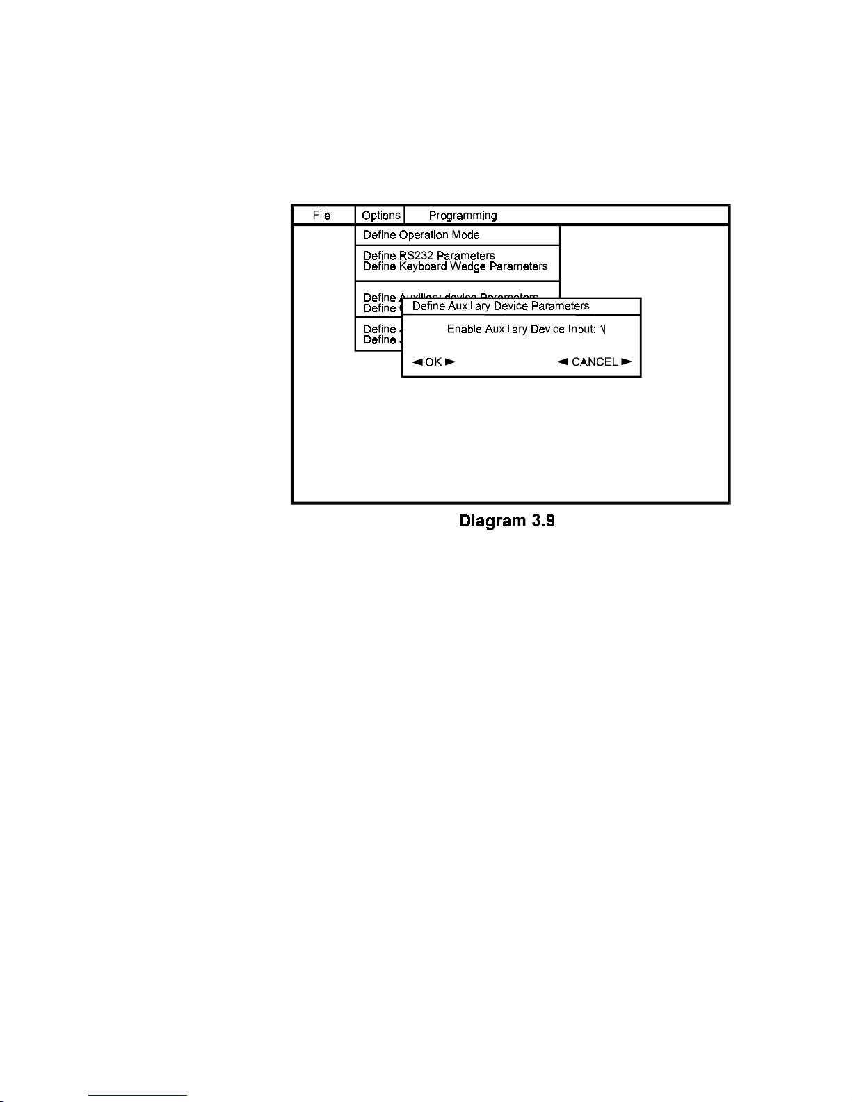
If it is advantageous in your application, you may assign
prefix identifiers for the 101/102 keyboard data. Pressing
[ENTER] on the MESSAGE PREFIX button opens the
PREFIX window (see Diagram 3.8). The prefix is only one
character in length. The character in the prefix will automatically be converted into the hexadecimal equivalent. The
lookup button opposite each hexadecimal character allows
access any ASCII character for use in the prefix. When you
are satisfied with the settings, scroll to OK or press [ALT+O]
to accept your choice. You will return to the Keyboard
Wedge Parameters window.
24
Custom Programming
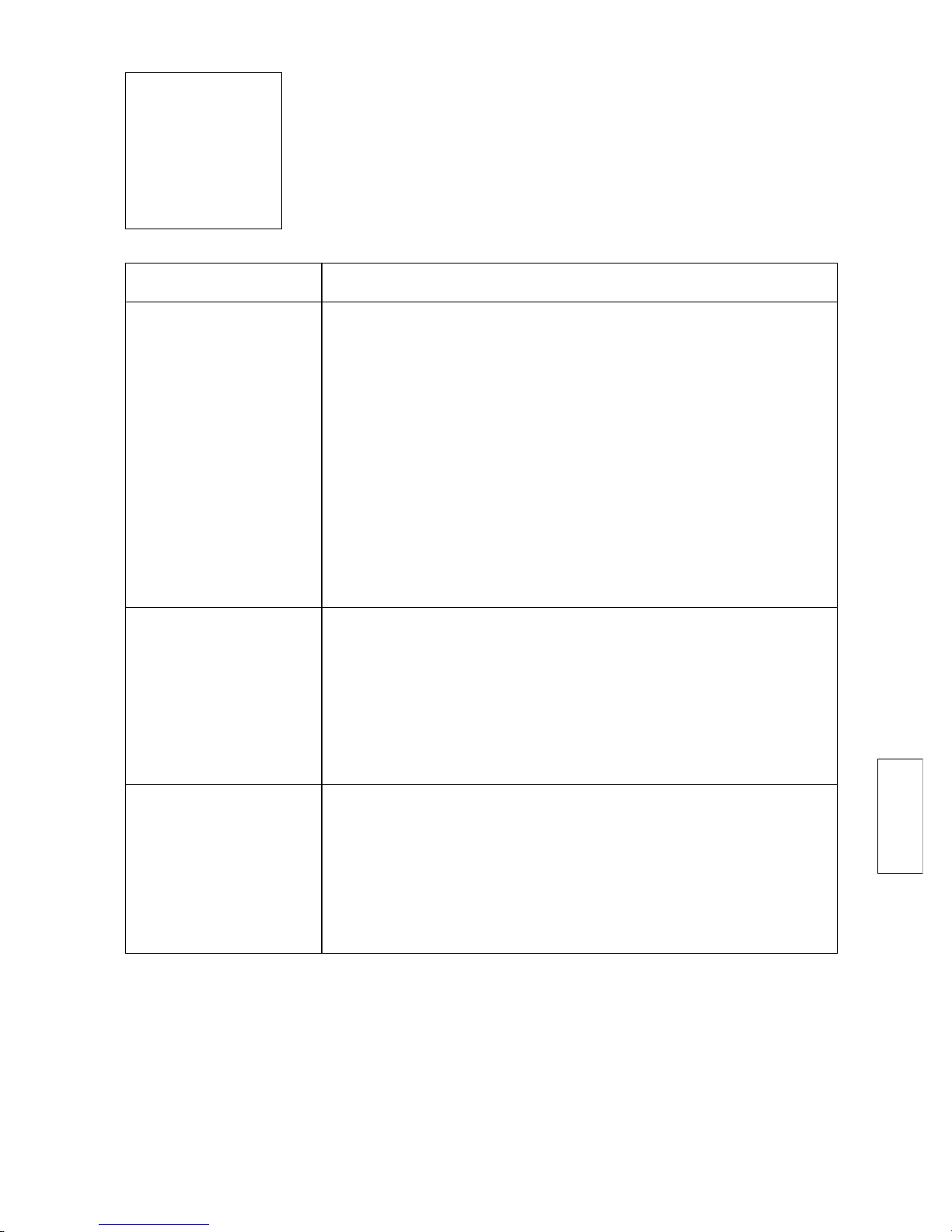
Step 6: Enable/Disable Auxiliary Device
Scroll [¯] to DEFINE AUXILIARY DEVICE PARAMETERS
and press [ENTER]. A window similar to Diagram 3.9
appears.
If you will be attaching an RS232 input device (e.g., bar code
scanner) to the AUX RS232 port on the Jarltech keyboard,
then its input must be enabled (Ö) in this window.
Scrolling to OK or pressing [ALT+O] in the Auxiliary Device
Parameters window accepts your choices and returns to the
Main Menu. Press [F2] to save your input.
Step 7: Define Card Reader Parameters
The card reader parameters facilitates effective utilization of
the information contained on a magnetic stripe.
Scroll [¯] to DEFINE CARD READER PARAMETERS and
press [ENTER]. A window similar to Diagram 3.10 appears.
The parameter settings are indicated by a check mark (Ö). If
you will be using the integrated card reader with the Jarltech
keyboard, please ensure that the card reader input is enabled.

25
Custom Programming
Message Prefix may be appended to data coming from the
card reader. Pressing [ENTER] on the MESSAGE PREFIX
button opens the PREFIX window (see Diagram 3.11). The
prefix can be just only one character in length. The prefix
character is automatically converted into hexadecimal form.
The lookup button opposite the hexadecimal will access any
ASCII character for use in the prefix. When you are satisfied
with the settings, scroll to OK or press [ALT+O] to accept
your choice and return to the Options window. Press [F2] to
save your input.

26
Custom Programming
The Jarltech keyboard parameters allow for the specification
of keyboard model, key characteristics and keyboard identifiers. Scroll [¯] to DEFINE JARLTECH KEYBOARD PARAMETERS and press [ENTER]. A window similar to Diagram 3.12
appears.
If you are using the tactile keyboard version of Series 8010,
chose Model 8010T, otherwise the membrane keyboard
version is Model 8010M.
Step 8: Define Jarltech Keyboard Parameters
ENABLE KEYBOARD INPUT must be checked (Ö) if input
from the Jarltech keyboard is desired.
Key Roll Over Mode, if enabled (Ö), allows the repeat
transmission of more than one key at a time. For example, if
you pressed three keys at the same time which send 1, 2 and
3 respectively, then the data sent to the host computer would
look like:
123123123123123123123123123123. . .
When Key Roll Over Mode is disabled, data is sent in the
same fashion as the standard IBM 101/102 keyboard. Using
the same example, the data would be sent as:
123333333333333333333333333333. . .

27
Custom Programming
The repeating 3 is becaused that the key of 3 is enabled
the repeat mode in Diagram 3.13. The Message Prefix may be
appended the beginning of data from the keyboard. The
prefix may be used to identify data from the Jarltech keyboard
to differentiate it from other data sources. i.e. :
The data transmitted to the host computer would look like:
<8010 Keyboard prefix><key data>
<key data>
<key data>
<card prefix><track1, track2, track3 . . .
Pressing [ENTER] on the MESSAGE PREFIX button opens
the PREFIX window (see Diagram 3.13). The prefix is just one
character in length. The prefix character is automatically
converted into hexadecimal form. The lookup button opposite the hexadecimal will access any ASCII character for use
in the prefix. When you are satisfied with the settings, scroll
to OK or press [ALT+O] to accept your choice and return to
the previous window.

28
Custom Programming
The KEY SPECIFICATIONS may be adjusted to suit your
timing preferences:
CLICK TIME refers to the duration of the audible tone from
when the key is first pressed.
REPEAT RATE refers to the rate at which a key will repeat if
continuously pressed.
DELAY BEFORE REPEAT refers to the time elapsed from
when a key is first pressed until it starts to continuously
repeat.
When you are satisfied with your entries for the Jarltech
keyboard parameters, press [ALT+O] to return to the Main
Menu. Press [F2] to save your input.
Step 8: Define Jarltech Keyboard Layouts
The Jarltech keyboard allows for memory of one keyboard
map or layout. Each key on a keyboard map may be uniquely
defined.
Scroll [¯] to DEFINE JARLTECH KEYBOARD LAYOUTS and
press [ENTER]. A window similar to Diagram 3.14 appears.

29
Custom Programming
The keys may be defined one by one. Using the arrow keys,
scroll to any key where you wish to begin programming and
press [ENTER]. A KEY DEFINITIONS window similar to
Diagram 3.15 appears. ENABLE CLICK and ENABLE
REPEAT allow you to choose on a key-by-key basis whether
to include the same click and repeat features which were
defined in the Jarltech Keyboard Parameters window (Diagram 3.12).
The ENABLE KEY function, when checked (Ö), allows the
key data to be sent to the host. When using dual or quad
key caps with the 8010T tactile keyboard, only a single key
under the key cap needs to be defined and enabled.
The adjacent keys under the same key cap should be disabled. Disabled keys will display as <**> on the keyboard
map.
Add Shift, CTRL, ALT to key allows to add Shift, CTRL,ALT
attribute to each key.
Enable ASCII mode allows user to use the ALT-key pad (at
the right side of 101/102 keyboard) to input the data to each
key. For example, you can press down the ALT key and
type 0, 0, 4 key on the keypad at the right side of 101/
102 keyboard to define the K data to the key. If disable
the ASCII Mode and press <CTRL> + <d> to define a key
then you will get ^d.

30
Custom Programming
Selecting the DEFINE KEY DATA button and pressing
[ENTER] brings up a window similar to that in Diagram 3.16).
Type the data that you wish to assign to the particular key.
When you are satisfied with your data input for the particular
key, press [ACT+X]. A window similar to Diagram 3.17 will
appear providing options to accept, abort, clear or add
functions to the current key data. Scroll to the function you
desire and press [ENTER].
After defining the key data and setting the key functions
according to your requirements,press [ALT+O] to return to
the DEFINE KEYBOARD MAP window.

31
Custom Programming
Remember to save your input often. You may press the [F2]
key at any time during the data input process except while
you are in the DEFINE KEY DATA window. To exit the
SAVE window, press [ESC].
Use the arrow keys or [TAB] key to the scroll to next key that
you wish to program and press [ENTER]. Repeat the process
until you have defined data for each key on the 8010 keyboard layout.
NOTE:
When you are satisfied with your entries for the Jarltech
keyboard layout, press [ALT+O] to return to the Main Menu.
Be sure to save your map file. If you wish to save the
information to a current file, then just press [F2] or scroll to
the FILE menu, select SAVE and press [ENTER].
If you wish to save your newly input data to a file other than
the current file, then choose the SAVE AS function from the
FILE menu. Provide a new name for the file and select OK to
save it.
Step 9: Save Your Keyboard Map Input

32
Custom Programming
Step 10: Program Jarltech Keyboard
Once you have completed and saved the data input which
customizes the Jarltech keyboard to suit your application
requirements, you are ready to program the keyboard. Scroll
[® ] to the PROGRAMMING menu (shown in Diagram 3.18).
The Jarltech keyboard may be programmed via the RS232 port
or the IBM keyboard port.
If you are programming via the RS232 port, connect the
programming cable to the HOST port on the Jarltech keyboard and to one of the RS232 communication ports of your
computer. Select PROGRAM KEYBOARD VIA RS232 and
press [ENTER]. Select the communication port which
matches your computer connection and press [ENTER]. A
box similar to that in Diagram 3.19 will appear. Press the
programming switch on the rear panel of the 8010 keyboard.
The screen will change to a display of the address and data
indicating that programming is underway. The keyboard will
beep to indicate that the programming was successful.

33
Custom Programming
If you are programming via the keyboard port, connect the
keyboard cable to the Jarltech keyboard port and the IBM
keyboard port. Select PROGRAM KEYBOARD VIA IBM
KEYBOARD WEDGE and press [ENTER]. A box similar to
that in Diagram 3.19 will appear,after which the screen will
change to a display of the address and data indicating that
programming is underway. The keyboard will beep to indicate
that the programming was successful.
The function READ KEYBOARD SETTINGS VIA RS232
provides the capability of reading an existing Jarltech 8010
keyboard map into active computer memory. That keyboard
map may then be downloaded into another Jarltech 8010
keyboard via either the RS232 interface or the keyboard
wedge interface using the above programming procedure.
After activing this function, press the programming switch on
the panel of the keyboard to start reading the map from this
keyboard.
Please wait some seconds before the "beep" indication for
successful programming appears as the software has to
initialize the download data to the keyboard. Press Esc
to exit after the beep indication (see Diagram 3.20).
NOTE:

34
Custom Programming

35
4
Operating Your Keyboard
The Jarltech Series 8010 keyboards may be operated in
conjunction with your host computer or terminal using either
a keyboard wedge interface or an RS232 interface. As your
requirements change in the future, the keyboards may be
reprogrammed to match the interface you require.
Step 1: Connect keyboard to computer
The Jarltech keyboard connections for RS232 or keyboard
wedge interface are the same as those described in Chapter 2.
Please refer to Diagram 2.1 for RS232 mode or Diagram 2.2 for
keyboard wedge mode.
Step 2: Connect Auxiliary RS232 Device to Keyboard
The AUX 1 port on the rear panel of the keyboard is available
for an RS232 input device, as in Diagram 4.1. Be sure to
check the pin assignments of the RS232 device to confirm
that it match the pin assignment of the Jarltech keyboard
AUX 1 Port (see Specifications in Appendix I).

36
Operating Your Keyboard
Step 3: Using the Optional Card Reader
An internal magnetic stripe decoder is configured on the
Jarltech 8010 circuit board for connection with a card reader.
If your keyboard purchase included an attached magnetic
stripe card reader and you programmed its parameters
according to Step 7 in Chapter 3, then the card reader is now
ready for use.
37
5
Troubleshooting
Situation Solution
Check the cable connections according to the descrip-
tions in Chapter 2. For RS232 programming and operation, be sure that the power supply is connected.
When programming via RS232, be sure that the correct
communication port has been selected. If the port
selection is correct, perhaps the computer RS232 interface is defective or not compatible with the 8010 keyboard. Because of the bidirectional protocol during
programming, some UART chip sets cannot be used for
programming the 8010 keyboard. Try another interface
card.
Check the cable connections of the keyboard and
adaptors (if used, e.g., PS/2 keyboard plug). Does the
keyboard beep correctly when the power is turned on?
Open 8010.EXE to confirm that you selected the correct
operation of the 8010 keyboard (RS232 vs. keyboard
wedge).
Open 8010.EXE to confirm that you selected the correct
operation of the 8010 keyboard (RS232 vs. keyboard
wedge).
The downloading
of the keyboard
map from the
computer to the
8010 keyboard
does not work.
The 8010 key-
board does not
transmit any data.
The 8010 key-
board transmits
data other than
that which was
programmed.

38

39
A
Appendix I
Specifications
Model 8010T
Keyboard
Model 8010M
Keyboard
Power Requirements
Physical
Communication
Ports
Tactile keyboard
7 rows x 15 columns
Cherry keyswitch
ABS plastic key caps
Single, dual and quadruple key caps available
User-definable key layout
Membrane switch keyboard
8 rows x 15 columns
User-definable key layout
RS232 interface: +12V DC from host computer or through
adaptor from external 110/220V AC source with polarity as
follows:
Keyboard interface: +5V DC from host computer
Dimensions: 305mm (L) x 175mm (W) x 45mm (H)
Weight: 750g
One internal connector for TTL-signal magnetic stripe
reader
One RS232 input-output HOST port
One RS232 input AUX port
One keyboard port

40
Specifications
RS232 HOST Port (Female)
#1: +5V DC Power #7: RTS
#2: RX #8: CTS
#3: TX #9: +12V DC power
#5: Ground
RS232 AUX1 Port (Male)
#1: +12V DC Power #6: RTS
#3: RX #9: +5V DC Power
#5: Ground
Connector Pin
Assignments
Keyboard Port
#1: Keyboard data
#3: +5 V
#4: Ground
#5: Keyboard clock

41
A
Appendix II
Step 3: Copy text with transparency
Step 4: Color key caps
Step 5: Laminate with thin plastic
Step 1: Copy to transparency
Step 2: Layout text on word processor
Included in your purchase of the Jarltech Model 8010M
keyboard is a 120-key layout template. This is intended to
maximize the utility and flexibility you derive from your
keyboard. Attend to the following instructions for best
results.
Photocopy the keyboard layout template on to a transparency. Keep this transparency and the original template is
safe storage for making future templates.
Layout the text for each key position using word processing
application software on the computer. Print your file.
Lay the transparency over the top of the printed text and
photocopy to produce a keyboard layout on paper.
Color-code the key caps according to your own requirements.
Bright-colored highlighter pens are easy to read when
finished.
Trim around the keyboard layout tight to its borders and then
laminate the keyboard layout with lamination plastic. Please
be sure to use thin lamination plastic. Thick plastic impedes
effective key response
8010M Template Guide

42
8010M Template Guide
Step 6: Install membrane on keyboard
Trim the laminated keyboard map so that it is just slightly
larger than the membrane switch plate of 8010M. Lay the map
on the membrane plate and tuck its edges under the keyboard
housing.
It is important to check that the keys on your keyboard
layout are exactly in line with the keys on the membrane
keypad.
NOTE:

43
A
Appendix III
Once customer finishing his own map (my.map) design,
besides the program through our 802x.exe, we also provide
customers a quick way for programming via RS232 under
DOS which is especially useful for multi-terminals programming.
You can use the parameters [c], [f] and [a] to achieve this
function.
Example:
8010 /c:1 /f:my.map /a
c: com port (COM1)
f: map name (MY.MAP)
a: parameter for quick down loading
Quick Programming

44

45
A
Appendix IV
If you are going to down load the map which was created by
POS.EXE of 8001 or 8002 keyboard into the 8010 keyboard.
Hereunder is the procedure to be followed:
STEP 1: Connect 8010 keyboard to your computer Via
RS232 port or keyboard port (Ref diagram 2.1, 2.2)
STEP 2: Copy POS.EXE and your map to the same directory
as 8010.EXE.
STEP 3: Excute the POS.EXE V7.1r or later.
STEP 4: Select Programming option of Main menu.
STEP 5: Select Setup 8001/2 and 8081/2.
STEP 6: Retrieve the map which you want down load to
8010. The communication parameters of this map
should be same as the connection of step 1.
STEP 7: Select programming keyboard setting
STEP 8: Select use 8010 IBM Translate to download
keyboard wedge map or select use 8010 NO
Translate to download the RS232 map.
STEP 9: If you are using the RS232 programming, please
press the programming switch on the rear panel of
8010 to starting to program.
Translate the map of 8001or 8002 to 8010

46

47
1. Q : How to program a quad key correctly?
A : For Programming a quad key,please program one of the
four keys with data only and disable the other three
keys.
2. Q : Why we can not program this 8010 keyboard through
the RS232 port?
A : 1. Check your setting in Diagram 3.5 if correct.
2. Try to disable the mouse driver. May be this com
port is occupied by an unreliable mouse driver.
3. Remember to press the programming switch on the
rear panel of the keyboard.
Frequently Asked Questions
Appendix V
A

48

49
Appendix VI
A
Application Under Windows
Please read this page carefully before you use our keyboard
series 8010 in Windows applications.
1. We don't recommend to use the programming utility
801x.exe in Win31/95/NT multi-tasking environments due
to the direct keyboard port access. We recommend to use
the pure MS-DOS mode for programming the keyboards.
2. When you use series 8010 keyboard under Windows
applications or if you are running your DOS application in
a DOS-Window, we recommend you to set up the following
parameters which will make your operation in Windows
more comfortable. Otherwise the keyboard data transmission could be disturbed, caused by timing problems with
the CPU/mainboard/keyboard chip/driver type used in your
system and a different handling of keyboard scan codes in
DOS and windows.
(1)
Under DEFINE KEYBOARD WEDGE PARAMETERS,
(i) Please select both inter-scan code delay and intercharacter delay at value 5. (ii) Under DEFINE ASCII
to IBM CONVERSION PREFERENCES, please enable
USE ENTER, NOT CTRL+M.
These settings had been done on the DEFAULT.MAP in
the utility diskette since August, 5 1997.
(2) To use a keyboard language driver, please edit the
AUTOEXEC.BAT with:
CD\C:\windows\command
KEYB XX,,C:\WINDOWS\COMMAND\KEYBRD2.SYS
(where xx represents the country)
The KEYBRD2.SYS is an alternative keyboard table to
the standard KEYBOARD.SYS which allows a more
DOS-compatible behaviour.
NOTE:


Copyright@2000
Jarltech International Inc.
Printed in Taiwan
ISSUED: JUN.,2000-V2.1
 Loading...